Table of Contents
Advertisement
Quick Links
Advertisement
Table of Contents

Related Manuals for Crestron TPS-IMPC


Summary of Contents for Crestron TPS-IMPC
- Page 1 Crestron TPS-IMPC Interface Module Operations Guide...
- Page 2 This document was prepared and written by the Technical Documentation department at: Crestron Electronics, Inc. 15 Volvo Drive Rockleigh, NJ 07647 1-888-CRESTRON All brand names, product names and trademarks are the property of their respective owners. ©2003 Crestron Electronics, Inc.
-
Page 3: Table Of Contents
Crestron TPS-IMPC Contents Interface Module: TPS-IMPC Introduction...1 Features & Functions...1 Specifications...1 Physical Description ...2 Industry Compliance...7 Setup...7 Network Wiring ...7 Hardware Hookup...8 Problem Solving...10 Troubleshooting...10 Further Inquiries ...11 Future Updates...12 Return and Warranty Policies ...13 Merchandise Returns / Repair Service ...13 CRESTRON Limited Warranty ...13... -
Page 5: Interface Module: Tps-Impc
Crestron TPS-IMPC Interface Module: TPS-IMPC Introduction Features & Functions The TPS-IMPC is an interface module designed for, and included with the Crestron sleek design of the touchpanel base left little room for all the connectors that define the touchpanel's versatility. Furthermore, since the panel is not a stationary user interface, it is impractical to have an excessive amount of cable connections directly to the touchpanel. -
Page 6: Physical Description
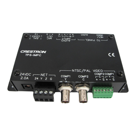
2.81 in (7.12 cm) 1.25 in (3.18 cm) Ports There are nine ports that serve various functions on the TPS-IMPC. Refer to the following diagrams and descriptions of each port. 2 • Interface Module: TPS-IMPC 5.82 in (14.78 cm) 5.32 in (13.52 cm) - Page 7 NOTE: BNC connectors are physically located next to the twisted pair connectors. Image is for illustration purposes only. Refer to the physical view of the TPS-IMPC on page 2 for actual connector positions. NOTE: The TPS-IMPC allows the use of either balanced or unbalanced signals for video input.
- Page 8 Interface Module CAUTION: If power is provided to the TPS-IMPC from the +24VDC on a Cresnet connector or the PW-2420RU, power must not be applied to the power input on the touchpanel base. NOTE: When power is supplied through this connector, Crestron recommends disconnecting the +24 VDC on the Cresnet connector (if it is connected).
- Page 9 Operations Guide - DOC. 6162 PIN DESIGNATION GND/Shield Audio Input Ground/Shield GND/Shield Mic Output Ground/Shield Interface Module: TPS-IMPC • 5 Interface Module DESCRIPTION Left Input (Positive) Left Input (Negative) Right Input (Positive) Right Input (Negative) Mic Output (Positive)
- Page 10 To select the twisted pair connector for balanced video, the DIP switch for the respective video source must be in the “UP” position. To use the coaxial connector(s) for unbalanced video, the DIP switch must be in the “DOWN” position. 6 • Interface Module: TPS-IMPC Shield Left Positive Shield...
-
Page 11: Industry Compliance
Crestron TPS-IMPC Industry Compliance As of the date of manufacture, the TPS-IMPC has been tested and found to comply with specifications for CE marking and standards per EMC and Radiocommunications Compliance Labelling (N11785). Setup Network Wiring CAUTION: Use only Crestron power supplies for Crestron equipment. -
Page 12: Hardware Hookup
Repeat the procedure for the other three conductors. Hardware Hookup The TPS-IMPC serves as an interface between the touchpanel and the Cresnet system. Refer to the illustration after this paragraph for proper connections; apply power last. When making network connections to a control system or Cresnet peripherals, refer to “Network Wiring”... - Page 13 FOR EACH VIDEO SIGNAL NOTE: The included AUDIO cable has a connector with a blue cover to match the blue connector on the TPS-IMPC. As older AUDIO cables may not have the blue cover, be sure to insert the AUDIO cable into the AUDIO port.
-
Page 14: Problem Solving
No power to touchpanel. Video window on touchpanel has no display. (continued on next page) 10 • Interface Module: TPS-IMPC POSSIBLE CAUSE(S) Touchpanel is not Confirm that power is receiving power. supplied via the power pack or the Cresnet connector (not both). -
Page 15: Further Inquiries
Inspect connector pins. If bent, connector pins. carefully re-straighten. If broken, contact Crestron customer service. Touchpanel is set Switch to “composite” video. to auto-detect or S- video when two composite signals are plugged into the TPS-IMPC. Interface Module: TPS-IMPC • 11 Interface Module... -
Page 16: Future Updates
Future Updates As Crestron improves functions, adds new features, and extends the capabilities of the TPS-IMPC, additional information may be made available as manual updates. These updates are solely electronic and serve as intermediary supplements prior to the release of a complete technical documentation revision. -
Page 17: Return And Warranty Policies
All brand names, product names, and trademarks are the sole property of their respective owners. Windows is a registered trademark of Microsoft Corporation. Windows95/98/Me and WindowsNT/2000 are trademarks of Microsoft Corporation. Operations Guide - DOC. 6162 Interface Module Interface Module: TPS-IMPC • 13... - Page 18 Interface Module Crestron TPS-IMPC This page intentionally left blank. 14 • Interface Module: TPS-IMPC Operations Guide - DOC. 6162...
- Page 19 Crestron TPS-IMPC Interface Module This page intentionally left blank. Interface Module: TPS-IMPC • 15 Operations Guide - DOC. 6162...
- Page 20 Crestron Electronics, Inc. Operations Guide - DOC. 6162 15 Volvo Drive Rockleigh, NJ 07647 06.03 Tel: 888.CRESTRON Fax: 201.767.7576 Specifications subject to www.crestron.com change without notice.