Endress+Hauser Liquiphant FTL51B Density Operating Instructions Manual
Vibronic density measurement for liquids
Hide thumbs
Also See for Liquiphant FTL51B Density:
- Operating instructions manual (64 pages) ,
- Brief operating instructions (40 pages) ,
- Safety instruction (24 pages)

Related Manuals for Endress+Hauser Liquiphant FTL51B Density


Summary of Contents for Endress+Hauser Liquiphant FTL51B Density
- Page 1 Products Solutions Services BA01974F/00/EN/03.23-00 71624355 2023-09-30 Valid as of version 01.00.zz Operating Instructions Liquiphant FTL51B Density Vibronic Density measurement for liquids...
- Page 2 Liquiphant FTL51B Density Order code: XXXXX-XXXXXX Ser. no.: XXXXXXXXXXXX Ext. ord. cd.: XXX.XXXX.XX Serial number www.endress.com/deviceviewer Endress+Hauser Operations App A0023555 Endress+Hauser...
-
Page 3: Table Of Contents
Liquiphant FTL51B Density Table of contents Table of contents About this document ....5 Electrical connection ....20 Purpose of this document . - Page 4 Table of contents Liquiphant FTL51B Density Accessories for Density Computer FML621 ......30 14.1 General ......30 14.2 Extension cards .
-
Page 5: About This Document
Liquiphant FTL51B Density About this document About this document Purpose of this document These Operating Instructions contain all the information that is required in the various phases of the life cycle of the device: from product identification, incoming acceptance and storage, to mounting, connection, operation and commissioning through to troubleshooting, maintenance and disposal. -
Page 6: Symbols In Graphics
For an overview of the scope of the associated Technical Documentation, refer to the following: • Device Viewer (www.endress.com/deviceviewer): Enter the serial number from the nameplate • Endress+Hauser Operations app: Enter serial number from nameplate or scan matrix code on nameplate. 1.3.1 Standard documentation Document type: Operating Instructions (BA) Installation and initial commissioning ‒... -
Page 7: Intended Use
Modifications to the device Unauthorized modifications to the device are not permitted and can lead to unforeseeable dangers. ‣ If, despite this, modifications are required, consult with Endress+Hauser. Repair To ensure continued operational safety and reliability: ‣ Only perform repair work on the device if this is expressly permitted. -
Page 8: Product Safety
It meets the general safety standards and legal requirements. It also complies with the EU directives listed in the device-specific EU Declaration of Conformity. Endress+Hauser confirms this by affixing the CE mark to the device. IT security We only provide a warranty if the device is installed and used as described in the Operating Instructions. -
Page 9: Product Design
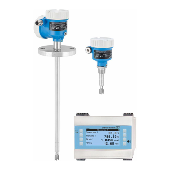
Liquiphant FTL51B Density Incoming acceptance and product identification Product design A0046337 1 Product design: Liquiphant FTL51B Housing with electronic insert FEL60D and cover Temperature spacer, pressure-tight feedthrough (second line of defense), optional Process connection with flange (optional) Process connection with thread (optional) -
Page 10: Product Identification
All of the information on the measuring device is displayed along with an overview of the scope of technical documentation provided. • Enter the serial number on the nameplate into the Endress+Hauser Operations app or scan the 2-D matrix code on the nameplate with the Endress+Hauser Operations app 4.2.1... -
Page 11: Mounting
Liquiphant FTL51B Density Mounting Mounting Mounting instructions • Any orientation for compact version or version with a pipe length of up to 500 mm (19.7 in)approx. • Vertical orientation from above for device with long pipe • Minimum distance between the fork tip and the tank wall or pipe wall: 10 mm (0.39 in) A0039739 ... -
Page 12: Flow Velocity - Installation In Piping
Mounting Liquiphant FTL51B Density 5.1.1 Flow velocity - Installation in piping Install the tuning fork within the medium flow • Flow velocity: < 2 m/s (6.56 ft/s) per second • Prevents the formation of air bubbles (1) A0039718 5... -
Page 13: Correction Factor
Liquiphant FTL51B Density Mounting ≥5×DN ≥2×DN >750 (29.5) >250 (9.84) A0039700 7 Installing the inlet run. Unit of measurement mm (in) Outlet run To comply with the accuracy specification, the outlet run must meet the following requirements: Outlet run: ≥ 2x DN (nominal diameter) - min. 250 mm (9.84 in) The pressure and temperature sensor must be installed on the outlet side of the flow direction after the Liquiphant density sensor. - Page 14 Mounting Liquiphant FTL51B Density Standard installation Correction factor "r" as a factor of height "h", for entering in the Density Computer FML621 or ReadWin2000: 12 mm (0.47 in) 1.0026 14 mm (0.55 in) 1.0016 16 mm (0.63 in) 1.0011 18 mm (0.71 in) 1.0008...
- Page 15 Liquiphant FTL51B Density Mounting 80 mm (3.15 in) 1.0008 82 mm (3.23 in) 1.0006 84 mm (3.31 in) 1.0005 86 mm (3.39 in) 1.0004 88 mm (3.46 in) 1.0003 90 mm (3.54 in) 1.0003 92 mm (3.62 in) 1.0002 94 mm (3.70 in) 1.0002...
-
Page 16: Avoid Buildup
Mounting Liquiphant FTL51B Density 92 mm (3.62 in) 1.0002 94 mm (3.70 in) 1.0001 96 mm (3.78 in) 1.0001 98 mm (3.86 in) 1.0001 100 mm (3.94 in) 1.0001 >100 mm (3.94 in) 1.0000 5.1.4 Avoid buildup NOTICE The presence of buildup or corrosion on the tuning fork affects the result of the measurement and must be avoided! ‣... -
Page 17: Weld-In Adapter With Leakage Hole
Liquiphant FTL51B Density Mounting A0039742 10 Examples of support in the event of dynamic load 5.1.7 Weld-in adapter with leakage hole Weld in the weld-in adapter in such a way that the leakage hole is pointing downwards. This enables any leaks to be detected quickly. -
Page 18: Installation
Mounting Liquiphant FTL51B Density 5.2.2 Installation Aligning the tuning fork using the marking A0039125 12 Position of the tuning fork when installed horizontally in the vessel using the marking Installing the device in piping NOTICE Incorrect alignment of the tuning fork Vortices and eddies can falsify the measuring result. - Page 19 Liquiphant FTL51B Density Mounting A0034852 14 Screwing in the device Aligning the cable entry 4 3.5 Nm A0037347 15 Housing with external locking screw and drip loop Housings with locking screw: • The housing can be turned and the cable aligned by turning the locking screw.
-
Page 20: Sliding Sleeves
Electrical connection Liquiphant FTL51B Density Sliding sleeves For more details, see the "Accessories" section. Post-mounting check Is the device undamaged (visual inspection)? Does the measuring device meet the measuring point specifications? For example: • Process temperature • Process pressure •... -
Page 21: Connecting Protective Earth (Pe)
Liquiphant FTL51B Density Electrical connection 6.2.2 Connecting protective earth (PE) When the device is used in hazardous areas, it must always be included in the potential equalization of the system, irrespective of the operating voltage. This is possible by connecting to the inner or outer protective ground connection (PE). - Page 22 Electrical connection Liquiphant FTL51B Density Supply voltage U = 24 V ±15 %, only suitable for connecting to the Density Computer FML621 The device must be powered by a voltage supply categorized as "CLASS 2" or "SELV". Power consumption P < 160 mW Current consumption I < ...
-
Page 23: Connecting The Cables
Liquiphant FTL51B Density Electrical connection A0039632 18 Density measurement with Density Computer FML621 Liquiphant Density → Pulse output Temperature sensor, e.g. 4 to 20 mA output Pressure transmitter 4 to 20 mA output required for changes in pressure >6 bar... -
Page 24: Post-Connection Check
Electrical connection Liquiphant FTL51B Density 24/25 mm 8.0 Nm A0018023 19 Example of coupling with cable entry, electronic insert with terminals M20 coupling (with cable entry), example Conductor cross-section maximum 2.5 mm (AWG14), ground terminal on inside in housing + terminals on the electronics Conductor cross-section maximum 4.0 mm... -
Page 25: Operation Options
Liquiphant FTL51B Density Operation options Operation options Overview of operation options 7.1.1 Operating concept Operation with the Density Computer FML621. For details, see documentation for the Density Computer FML621. 7.1.2 Elements on the electronic insert Pulse – A0039683 20... -
Page 26: Operation
Operation Liquiphant FTL51B Density Operation Light signals Yellow LED Symbols, information Stable measurement Unstable measurement/process conditions Maintenance required Green LED Symbols, information / Power on / Power off Red LED Symbols, information No fault Maintenance required Device failure For more information, see the Technical Information for Liquiphant Density. -
Page 27: Firmware History
12.1.1 Repair concept Endress+Hauser repair concept • The devices have a modular design • Customers can carry out repairs For more information on service and spare parts, please contact your Endress+Hauser sales representative. 12.1.2 Repairs to Ex-approved devices WARNING Incorrect repair can compromise electrical safety! Explosion hazard! ‣... -
Page 28: Spare Parts
Accessories for Liquiphant Density Liquiphant FTL51B Density 12.2 Spare parts • Some replaceable device components are identified by a spare part nameplate. This contains information about the spare part. • All the spare parts for the measuring device, along with the order code, are listed in the W@M Device Viewer (www.endress.com/deviceviewer) and can be ordered. -
Page 29: Protective Cover For Single Compartment Housing, Aluminum Or 316L
Liquiphant FTL51B Density Accessories for Liquiphant Density 228.9 (9.01) 136.4 (5.37) 92.5 (3.64) 170.5 (6.71) 81 (3.19) 103 (4.06) A0039231 21 Protective cover for aluminum dual compartment housing. Unit of measurement mm (in) 13.2 Protective cover for single compartment housing, aluminum or 316L •... -
Page 30: Weld-In Adapter
Weld in the weld-in adapter in such a way that the leakage hole is pointing downwards. This enables any leaks to be detected quickly. For detailed information, see "Technical Information" TI00426F (Weld-in adapters, process adapters and flanges) Available in the Downloads area of the Endress+Hauser website (www.endress.com/downloads). Accessories for Density Computer FML621 14.1... -
Page 31: Extension Cards
Liquiphant FTL51B Density Technical data 14.2 Extension cards The device can be extended with a maximum of three universal or digital or current or Pt100 cards. FML621A-DA Digital • 6 x digital input • 6 x relay output • Kit with terminals and fixing frame... -
Page 32: Measuring Range
See safety instructions (XA): All data relating to explosion protection are provided in separate Ex documentation and are available from the Downloads area of the Endress+Hauser website. The Ex documentation is supplied as standard with all devices approved for use in explosion hazardous areas. -
Page 33: Pollution Degree
Liquiphant FTL51B Density Technical data Cable entries • M20 coupling, plastic, IP66/68 NEMA Type 4X/6P • M20 coupling, nickel-plated brass, IP66/68 NEMA Type 4X/6P • M20 coupling, 316L, IP66/68 NEMA Type 4X/6P • M20 coupling, 316L, hygienic, IP66/68/69 NEMA Type 4X/6P •... -
Page 34: Additional Technical Data
Technical data Liquiphant FTL51B Density 15.5 Additional technical data Current Technical Information: Endress+Hauser website: www.endress.com → Downloads. Endress+Hauser... -
Page 35: Index
Liquiphant FTL51B Density Index Index About this document W@M Device Viewer ..... 10, 28 Symbols - description ..... . . 5 Workplace safety . - Page 36 *71624355* 71624355 www.addresses.endress.com...