Endress+Hauser Liquiphant FTL51B Brief Operating Instructions
Vibronic point level switch for liquids
Hide thumbs
Also See for Liquiphant FTL51B:
- Operating instructions manual (64 pages) ,
- Brief operating instructions (29 pages) ,
- Safety instruction (24 pages)
Table of Contents
Advertisement
Quick Links
KA01429F/00/EN/02.21
71515031
2021-01-25
Products
Brief Operating Instructions
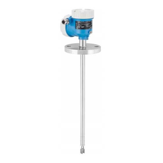
Liquiphant FTL51B
Vibronic
Point level switch for liquids
These Instructions are Brief Operating Instructions; they are
not a substitute for the Operating Instructions pertaining to
the device.
Detailed information about the device can be found in the
Operating Instructions and the other documentation:
Available for all device versions via:
• Internet:
www.endress.com/deviceviewer
• Smart phone/tablet: Endress+Hauser Operations App
Solutions
Services
Advertisement
Table of Contents

Related Manuals for Endress+Hauser Liquiphant FTL51B


Summary of Contents for Endress+Hauser Liquiphant FTL51B
- Page 1 Operating Instructions pertaining to the device. Detailed information about the device can be found in the Operating Instructions and the other documentation: Available for all device versions via: • Internet: www.endress.com/deviceviewer • Smart phone/tablet: Endress+Hauser Operations App...
- Page 2 Liquiphant FTL51B Order code: XXXXX-XXXXXX Ser. no.: XXXXXXXXXXXX Ext. ord. cd.: XXX.XXXX.XX Serial number www.endress.com/deviceviewer Endress+Hauser Operations App A0023555 Endress+Hauser...
-
Page 3: Table Of Contents
Liquiphant FTL51B Table of contents Table of contents About this document ............. . 3 Symbols . - Page 4 About this document Liquiphant FTL51B CAUTION This symbol alerts you to a dangerous situation. Failure to avoid this situation can result in minor or medium injury. NOTICE This symbol contains information on procedures and other facts which do not result in personal injury.
-
Page 5: Basic Safety Instructions
Liquiphant FTL51B Basic safety instructions Basic safety instructions Requirements for the personnel The personnel must fulfill the following requirements to carry out the necessary tasks, e. g., commissioning and maintenance: ‣ Trained, qualified specialists must have a relevant qualification for the specific function and task ‣... -
Page 6: Product Safety
It meets general safety standards and legal requirements. It also complies with the EC directives listed in the device-specific EC Declaration of Conformity. Endress+Hauser confirms this by affixing the CE mark to the device. IT security ... -
Page 7: Product Identification
(www.endress.com/deviceviewer): All the information about the measuring device and an overview of the Technical Documentation supplied are displayed. • Enter the serial number on the nameplate into the Endress+Hauser Operations App or use the Endress+Hauser Operations App to scan the 2-D matrix code (QR Code) on the nameplate 3.2.1... -
Page 8: Mounting
Mounting Liquiphant FTL51B Storage temperature –40 to +80 °C (–40 to +176 °F) Optional: –50 °C (–58 °F), –60 °C (–76 °F) 3.3.2 Transporting the device • Transport the device to the measuring point in the original packaging • Hold the device by the housing, temperature spacer, flange or extension pipe •... -
Page 9: Mounting Conditions
Liquiphant FTL51B Mounting A0037879 3 Installation examples for a vessel, tank or pipe Temperature spacer/pressure-tight feedthrough (optional) for tank with insulation and/or high process temperatures Mounting conditions 4.1.1 Take switch point into consideration Typical switch points, depending on the orientation of the point level switch (water +23 °C (+73 °F)) - Page 10 Mounting Liquiphant FTL51B 4.1.2 Take viscosity into consideration Low viscosity Low viscosity, e.g. water: < 2 000 mPa⋅s It is permitted to position the tuning fork within the installation socket. > 25 (0.98) A0033297 5 Installation example for low-viscosity liquids. Unit of measurement mm (in) Diameter of installation socket: at least 50 mm (2.0 in)
- Page 11 Liquiphant FTL51B Mounting 4.1.3 Avoid buildup • Use short installation sockets to ensure that the turning fork can project freely into the vessel • Install preferably flush mount on vessels or in pipes • Leave sufficient distance between the buildup expected on the tank wall and the tuning fork A0033239 ...
- Page 12 Mounting Liquiphant FTL51B A0033236 8 Take clearance into consideration 4.1.5 Support the device Support the device in the event of severe dynamic load. Maximum lateral loading capacity of the pipe extensions and sensors: 75 Nm (55 lbf ft). A0031874 ...
-
Page 13: Mounting The Measuring Device
Liquiphant FTL51B Mounting 4.1.6 Weld-in adapter with leakage hole Weld in the welding neck in such a way that the leakage hole is pointing downwards. This enables any leaks to be detected quickly. A0039230 10 Weld-in adapter with leakage hole Mounting the measuring device 4.2.1... - Page 14 Mounting Liquiphant FTL51B Installing in pipes • Flow velocities up to 5 m/s at a viscosity of 1 mm /s(cSt) and density 1 g/cm (SGU) Check for correct functioning in the event of other process medium conditions. • The flow will not be significantly impeded if the tuning fork is correctly aligned and the marking is pointing in the direction of flow.
-
Page 15: Sliding Sleeves
Liquiphant FTL51B Mounting Aligning the cable entry 4 0.7 Nm A0037347 14 Housing with external locking screw The locking screw is not tightened when the device is delivered. Loosen the external locking screw (maximum 1.5 turns). Turn the housing, align the cable entry. -
Page 16: Electrical Connection
Electrical connection Liquiphant FTL51B Electrical connection Connection conditions 5.1.1 Cover with securing screw In the case of devices for use in the hazardous area with a certain type of protection, the cover is sealed by a securing screw. NOTICE If the securing screw is not positioned correctly when the cover is screwed closed, the cover cannot provide secure sealing. - Page 17 Liquiphant FTL51B Electrical connection 5.2.2 2-wire AC (electronic insert FEL61) • Two-wire AC version • Switches the load directly into the power supply circuit via an electronic switch; always connect in series with a load • Functional testing without level change A functional test can be performed on the device using the test button on the electronic insert.
- Page 18 Electrical connection Liquiphant FTL51B U 19...253 V AC I max: 350 mA >0,7 >0,5 L1 N A0036060 16 2-wire AC, electronic insert FEL61 Endress+Hauser...
- Page 19 Liquiphant FTL51B Electrical connection Behavior of switch output and signaling ΔU <3.8 mA ΔU <3.8 mA <3.8 mA A0031901 17 Behavior of switch output and signaling, electronic insert FEL61 MAX DIP switch for setting MAX safety mode MIN DIP switch for setting MIN safety mode...
- Page 20 Electrical connection Liquiphant FTL51B Selection tool for relays 207 230 253 A0042052 18 Recommended minimum holding power/rated power for load Holding power/rated power in [VA] Operating voltage in [V] AC mode • Operating voltage: 24 V, 50 Hz/60 Hz •...
- Page 21 Liquiphant FTL51B Electrical connection Supply voltage WARNING Failure to use the prescribed power unit. Risk of potentially life-threatening electric shock! ‣ The FEL62 may only be powered by devices with safe galvanic isolation, as per IEC 61010-1. U = 10 to 55 V Observe the following as per IEC/EN61010-1: Provide a suitable circuit breaker for the device, and limit the current to 500 mA, e.g.
- Page 22 Electrical connection Liquiphant FTL51B Terminal assignment U = 10...55 V DC 350 mA I max: 350 mA 55 V >0,7 >0,5 0.5 A L+ L- A0036061 19 3-wire DC-PNP, electronic insert FEL62 Connection wiring with terminals Connection wiring with M12 plug in housing as per EN61131-2 standard...
- Page 23 Liquiphant FTL51B Electrical connection Behavior of switch output and signaling (L–) ΔU <100 µA (L–) (L–) ΔU <100 µA (L–) <100 µA (L–) A0033508 20 Behavior of switch output and signaling, electronic insert FEL62 MAX DIP switch for setting MAX safety mode...
- Page 24 Electrical connection Liquiphant FTL51B Supply voltage U = 19 to 253 V , 50 Hz/60 Hz / 19 to 55 V Observe the following as per IEC/EN61010-1: Provide a suitable circuit breaker for the device, and limit the current to 500 mA, e.g. by installing a 0.5 A fuse (slow-blow) in the phase (not the neutral conductor) of the supply circuit.
- Page 25 Liquiphant FTL51B Electrical connection Terminal assignment >0,7 U = 19...55 V DC >0,5 U 19...253 V AC 0.5 A A0036062 21 Universal current connection with relay output, electronic insert FEL64 When bridged, the relay output works with NPN logic...
- Page 26 Electrical connection Liquiphant FTL51B Behavior of switch output and signaling A0033513 22 Behavior of switch output and signaling, electronic insert FEL64 MAX DIP switch for setting MAX safety mode MIN DIP switch for setting MIN safety mode LED red for alarm...
- Page 27 Liquiphant FTL51B Electrical connection Connectable load Loads switched via 2 potential-free changeover contacts (DPDT) • I ≤ 6 A (Ex de 4 A), U~ ≤ AC 253 V; P~ ≤ 1 500 VA, cos φ = 1, P~ ≤ 750 VA, cos φ > 0.7 • I ≤ 6 A (Ex de 4 A) to DC 30 V, I DC ≤...
- Page 28 Electrical connection Liquiphant FTL51B Terminal assignment >0,7 >0,5 U = 9...20 V DC 0.5 A L- PE A0037685 23 DC connection with relay output, electronic insert FEL64 DC When bridged, the relay output works with NPN logic Connectable load Endress+Hauser...
- Page 29 Liquiphant FTL51B Electrical connection Behavior of switch output and signaling A0033513 24 Behavior of switch output and signaling, electronic insert FEL64 DC MAX DIP switch for setting MAX safety mode MIN DIP switch for setting MIN safety mode LED red for alarm...
- Page 30 Electrical connection Liquiphant FTL51B Power consumption P ≤ 150 mW with Nivotester FTL325P or FTL375P Behavior of output signal • OK status: MAX operating mode 150 Hz, MIN operating mode 50 Hz • Demand mode: MAX operating mode 50 Hz, MIN operating mode 150 Hz •...
- Page 31 Liquiphant FTL51B Electrical connection Connection cable • Maximum cable resistance: 25 Ω per core • Maximum cable capacitance: < 100 nF • Maximum cable length: 1 000 m (3 281 ft) Behavior of switch output and signaling 150 Hz 50 Hz...
- Page 32 2-wire NAMUR > 2.2 mA/ < 1.0 mA (electronic insert FEL68) • For connection to the isolating switch repeater as per NAMUR (IEC 60947-5-6), e.g. Nivotester FTL325N from Endress+Hauser • Signal transmission H-L edge 2.2 to 3.8 mA/0.4 to 1.0 mA as per IEC 60947-5-6 (NAMUR) on two-wire cabling •...
- Page 33 Liquiphant FTL51B Electrical connection Terminal assignment IEC 60947-5-6 8,2 V DC NAMUR – >0,7 >0,5 L- L+ A0036066 27 2-wire NAMUR ≥ 2.2 mA/≤ 1.0 mA, electronic insert FEL68 Endress+Hauser...
- Page 34 Electrical connection Liquiphant FTL51B Behavior of switch output and signaling 2.2...3.8 mA 0.4...1.0 mA 2.2...3.8 mA 0.4...1.0 mA < 1.0 mA A0037694 28 Behavior of switch output and signaling, electronic insert FEL68 MAX DIP switch for setting MAX safety mode...
-
Page 35: Post-Connection Check
Liquiphant FTL51B Electrical connection 5.2.10 Connecting the cables Required tools • Flat-blade screwdriver (0.6 mm x 3.5 mm) for terminals • Suitable tool with width across flats AF24/25 (8 Nm (5.9 lbf ft)) for M20 cable gland 24/25 mm 8.0 Nm A0018023 ... -
Page 36: Operation Options
Operation options Liquiphant FTL51B Are all the housing covers installed and tightened? Optional: Is the cover tightened with securing screw? Operation options Overview of operation options 6.1.1 Operating concept • Operation with button and DIP switches on the electronic insert •... - Page 37 Liquiphant FTL51B Operation options 6.1.3 Functional test using the button on the electronic insert • The functional test must be performed in the OK state: MAX safety and sensor free or MIN safety and sensor covered. • The LEDs flash one after another as a chaser light during the functional test.
-
Page 38: Led Module Vu120 (Optional)
Commissioning Liquiphant FTL51B The functional test with the test magnet acts in the same way as the functional test using the test button on the electronic insert. A0033419 32 Functional test with test magnet 6.1.5 Heartbeat diagnosis and verification with Bluetooth® wireless technology Access via Bluetooth®... -
Page 39: Switching On The Measuring Device
Liquiphant FTL51B Commissioning Switching on the measuring device During the power-up time, the device output is in the safety-oriented state, or in the alarm state if available: • For electronic insert FEL61, the output will be in the correct state after a maximum of 4 s following power-up. - Page 40 *71515031* 71515031 www.addresses.endress.com...