Table of Contents
Advertisement
Quick Links
Advertisement
Table of Contents

Related Manuals for EAS Electric M-THERMAL 2 R32 BIBLOCK


Summary of Contents for EAS Electric M-THERMAL 2 R32 BIBLOCK
- Page 1 ETHKH06A MANUAL DE INSTRUCCIONES INSTRUCTION MANUAL Escanee para ver este manual en otros idiomas y actualizaciones Scan for manual in other languages and further updates Manuel dans d'autres langues et mis à jour Manual em outras línguas e actualizações...
- Page 2 CONTEN...
- Page 4 ETHKH06A ETHKH10A ETHKH16A...
- Page 13 Img. 4-1...
- Page 14 . 4-3 . 4-4...
- Page 15 dos personas dos personas dos personas . 4-5...
- Page 16 ETHKH10A ETHKH16A ETHKH06A ① ② ③ ℃ ℃ ℃ ℃ ETHKH06A ETHKH10A ETHKH16A...
- Page 18 2.11 FHL1 FHL2 FHLn 2.10 14.2 14.1 Modbus 14.3...
- Page 20 2.11 2.10 FHL1 FHL2 FHLn Modbus...
- Page 21 FCU1 FCU2 FCUn 2.11 2.10 FHL1 FHL2 FHLn Modbus...
- Page 22 RAD.1 2.11 RAD.2 2.10 RAD.n 8.1 8.2 FHL1 FHL2 FHLn Modbus...
- Page 23 ETHKH06A ETHKH10A ETHKH16A...
- Page 24 como accesorio). Los elementos del interior de la unidad pueden estar calientes. Para obtener acceso a los componentes de la caja de control por ejemplo, para conectar el cableado de la instala te el panel de servicio de la caja de control. Desconecte el suministro eléctrico, es decir, la fuente de alimentación de la unidad exterior, la fuente de alimen- tación de la unidad interior, el calentador eléctrico y la fuente de alimentación adicional del calentador antes de retirar el panel de servicio de la caja de control.
- Page 25 Código Unidad de montaje Explicación El aire atrapado en el circuito de agua se eliminará automáticamente a través de la Válvula de purga automática válvula de purga automática. Vaso de expansión (5 l) Conexión del gas refrigerante Conexión del líquido refrigerante Cuatro sensores de temperatura determinan la temperatura del agua y del Sensores de temperatura refrigerante en varios puntos.
- Page 28 Para todas las pautas, instrucciones y especificaciones con respecto a las tuberías de refrigerante entre la unidad interior y la unidad exterior, consulte "Manual de (unidad exterior M-thermal )". CUIDADO Cuando conecte las tuberías de refrigerante, siempre use dos llaves para apretar o aflojar las tuercas. De lo con- trario, se pueden dañar las conexiones y provocar fugas en las tuberías.
- Page 29 : 2.11 2.10 FHL1 FHL2 FHLn Modbus...
- Page 30 Antes de continuar con la instalación de la unidad, compruebe lo siguiente: ● Presión máxima del agua ≤ 3 bares. ● La temperatura máxima del agua es ≤ 70 °C según el ajuste del dispositivo de seguridad. ● Utilice siempre materiales que sean compatibles con el agua utilizada en el sistema y con los materiales utilizados en la unidad.
- Page 31 8.5.3 Conexión del circuito de agua Las conexiones de agua deben realizarse correctamente de acuerdo con las etiquetas de la unidad interior, con respecto a la entrada de agua y la salida de agua. CUIDADO Tenga cuidado de no deformar la tubería de la unidad si aplica una fuerza excesiva al conectar la tubería. La deformación de una tubería puede causar un de la unidad.
- Page 32 NOTA Durante el llenado, es posible que no se pueda eliminar todo el aire del sistema. El aire restante se eliminará a través de las válvulas de purga automática durante las primeras horas de funcionamiento del sistema. Podría ser necesario añadir una pe- queña cantidad de agua tras la puesta en marcha.
- Page 34 25 T Modbus Código Unidad de montaje Código Unidad de montaje Unidad exterior SV2: válvula de 2 vías SV1: Válvula de 3 vías para el depósito de agua caliente Kit de energía solar sanitaria Interfaz de usuario Calentador de refuerzo Termostato de pared Contactor P_s: Bomba solar...
- Page 35 ETHKH06A ETHKH10A ETHKH16A ETHKH06A calent. ETHKH10A calent. ETHKH16A calent. ETHKH06A(calent. ETHKH10A(calent. ETHKH16A(calent. 9kW) 8.8.3 Precauciones al cablear el suministro eléctrico ● Utilice un terminal redondo de tipo ondulado para la conexión a la placa de terminales del suministro eléctrico. En caso de que no se pueda utilizar por razones inevitables, asegúrese de seguir las siguientes instrucciones.
- Page 36 Use el destornillador adecuado para apretar los tornillos del bornero. Los destornilladores pequeños pueden dañar la cabeza del tornillo e impedir un apriete adecuado. Apretar en exceso los tornillos del bornero puede dañarlos. Instale un diferencial y un fusible a la línea de alimentación. Compruebe que se están utilizando los cables especificados, que las conexiones tienen continuidad y que los cables se instalan de manera que no afecte a los terminales.
- Page 37 ( )...
- Page 39 ATCO...
- Page 41 ( )...
- Page 42 ( ) ( )...
- Page 43 : ATCO...
- Page 44 Power supply ATCO a) ) Procedimien ● Conecte el cable a los terminales apropiados tal como se muestra en la imagen. ● Fije el cable con bridas a los soportes para tal fin para evitar tensiones. ETHKH06A, ETHKH10A ETHKH16A...
- Page 45 ℃...
- Page 46 Estado: en la configuración del controlador con cable, si T4C2 <T4C1,intercambie los valores; si T1SETC1<T1SETC2, intercambie los valores. 9.2.1 Ajuste de las funciones El conmutador DIP S1, S2 está ubicado en la placa de control principal de la unidad interior (consulte " 8.3.1 Placa de con- trol principal de la unidad interior") y permite la configuración de la instalación del termistor de la fuente de calefacción adicional, la instalación del segundo calentador de respaldo interno, etc.
- Page 47 9.3 Puesta en marcha inicial con temperaturas exteriores bajas Durante el arranque inicial y cuando la temperatura del agua es baja, es importante que el agua se caliente gradualmente. De lo contrario, se pueden agrietar los pisos de cemento debido al rápido cambio de temperatura. Por favor, póngase en con- tacto con el contratista responsable de la construcción de las soleras de cemento para obtener más detalles.
- Page 48 9.5 Ajuste de la bomba La bomba se controla mediante una señal digital de modulación de ancho de pulso de bajo voltaje, lo que significa que la velocidad de rotación depende de la señal de entrada, la cual cambia en fun- ción del perfil de entrada.
- Page 49 ETHKH16A...
- Page 50 ▼▲...
- Page 51 Acerca de FOR SERVICEMAN (PARA EL 9.6.1 DHW MODE SETTING (AJUSTE DEL TÉCNICO) MODO DHW) "FOR SERVICEMAN" está diseñado para que el insta- DHW = agua caliente sanitaria lador configure los parámetros. Vaya a MENU > FOR SERVICEMAN > 1.DHW MODE SE- TTING.
- Page 52 9.6.5 TEMP. TYPE SETTING (AJUSTE TIPO TEMP.) 2 COOL MODE SETTING 2.1 COOL MODE Sobre TEMP. TYPE SETTING 2.2 t_T4_FRESH_C 2.0HRS 2.3 T4CMAX 43°C El ajuste TEMP. TYPE SETTING se usa para seleccio- 2.4 T4CMIN 20°C nar si la temperatura del caudal de agua o la temperatu- 2.5 dT1SC 5°C ra de la habitación se usa para controlar ON/OFF de la...
- Page 53 En este caso, el valor de configuración de la zona 1 es T1S, el valor de configuración de la zona 2 es T1S2. Si ajusta DOUBLE ZONE y ROOM TEMP. a YES, y mientras tanto ajusta WATER FLOW TEMP. a YES o NON, se mostrarán las páginas siguientes.
- Page 54 9 SERVICE CALL Si selecciona YES, se mostrarán las páginas siguientes: PHONE NO. 33512345678 MOBILE NO. 8613929145152 11 TEST RUN 11.1 POINT CHECK 11.2 AIR PURGE 11.3 CIRCULATION PUMP RUNNING CONFIRM ADJUST 11.4 COOL MODE RUNNING El número que se muestra en la interfaz de usuario es el 11.5 HEAT MODE RUNNING número de teléfono de su distribuidor local.
- Page 55 Cuando la unidad se encuentra en el modo de purga de aire, Durante el funcionamiento en modo de prueba HEAT MODE, se abre la válvula de 3 vías, se cierra la válvula de 2 vías. 60 s la temperatura seleccionada por defecto del agua es de 35 °C. más tarde, la bomba en la unidad (PUMPI) funciona durante 10 El IBH (calentador de refuerzo interno por sus siglas en inglés) minutos durante los cuales el conmutador de flujo no funciona.
- Page 56 Vaya a MENU > FOR SERVICEMAN > 12.SPECIAL Durante el precalentamiento del suelo, todos los botones FUNCTION. excepto OK dejan de estar operativos. Si desea apagar el precalentamiento del suelo, pulse OK. Antes de activar la calefacción por suelo radiante, si queda mucha cantidad de agua en el suelo, éste Se mostrará...
- Page 57 Con el cursor en OPERATE FLOOR DRYING, utilice ◄ Vaya a MENU > FOR SERVICEMAN > 13.AUTO ► para desplazarse hasta YES y pulse OK. Se mostrará RESTART la página siguiente: 13 AUTO RESTART 12.2 FLOOR DRYING UP 13.1 COOL/HEAT MODE DO YOU WANT TO TURN OFF THE 13.2 DHW MODE FLOOR DRYING UP FUNCTION?
- Page 58 Los parámetros relacionados con este capítulo se muestran en la tabla siguiente.
- Page 60 <...
- Page 61 10 PRUEBA DE Las verificaciones siguientes deben ser realizadas al menos una vez al año por personal cualificado. FUNCIONAMIENTO Y ● Presión del agua VERIFICACIONES FINALES Compruebe la presión del agua, si está por debajo de 1 bar, llene el agua del sistema. El instalador está...
- Page 62 12 SOLUCIÓN DE PROBLEMAS Esta sección proporciona información útil para diagnosticar y corregir ciertos problemas que pueden producirse en la unidad. Esta solución de problemas y las acciones correctivas relacionadas solo pueden ser llevadas a cabo por su técnico local. 12.1 Directrices generales Antes de iniciar los procedimientos para solucionar problemas, realice una inspección visual exhaustiva de la unidad y bus- que defectos evidentes, como conexiones sueltas o cableado defectuoso.
- Page 65 ℃...
- Page 66 CÓDIGO DE FALLO O PROTECCIÓN CAUSA DEL FALLO Y ACCIÓN CORRECTIVA ERROR 1. El circuito está cortocircuitado o abierto. Vuelva a conectar el cable co- rrectamente. Fallo en el caudal de agua (después 2. El caudal de agua es muy bajo. de 3 E8) 3.
- Page 67 CÓDIGO DE FALLO O PROTECCIÓN CAUSA DEL FALLO Y ACCIÓN CORRECTIVA ERROR Error del parámetro EE . Vuelva a escribir los datos EEprom. Fallo de la EE de la El chip EE está averiado, cámbielo. unidad interior La placa de control principal de la unidad interior está averiada, cámbiela por una PCB nueva.
- Page 68 En invierno, si la unidad presenta fallos E0 y Hb y la unidad no se repara a tiempo, la bomba de agua y el siste- ma de tuberías pueden dañarse por congelación, por lo que las fallos E0 y Hb deben solucionarse a tiempo.
- Page 69 ETHKH10A ETHKH06A ETHKH16A...
- Page 70 ETHKH06A ETHKH10A ETHKH16A ETHKH10A ETHKH06A ETHKH16A...
- Page 71 1) Comprobaciones del área Antes de comenzar cualquier trabajo en sistemas que contengan refrigerantes inflamables, debe hacer comprobaciones de seguridad para minimizar el riesgo de incendio. Para hacer cualquier reparación en el sistema de refrigerante, se deben cumplir las siguientes precauciones antes de hacer cualquier trabajo en el sistema. 2) Procedimiento Se debe seguir un procedimiento controlado para minimizar el riesgo de presencia de gas inflamable o vapores durante el trabajo.
- Page 72 b) Se debe prestar especial atención a las indicaciones siguientes para asegurar que la carcasa no se dañe al manipular los componentes eléctricos de forma que la protección pueda verse alterada. Esto incluye el daño a los cables, conexiones excesivas, terminales no conformes con las especificaciones originales, sellos dañados, montaje incorrecto de entradas de cable, etc.
- Page 73 disponible el 8 todos los s relacionados y eliminación...
- Page 75 . La calidad del agua se debe analizar antes de su uso; para evaluar criterios como el valor de pH, la conductividad, la concentración de iones de cloruro (Cl-), la concentración de iones de sulfuro (S2-), etc. Se indican algunos de los parámetros sobre los ingredientes químicos en la tabla siguiente: Acrilamida 0.10...
- Page 76 CONDICIONES DE LA GARANTÍA EAS ELECTRIC ofrece una garantía de reparación contra todo defecto de funcionamiento proveniente de la fabricación, incluyendo mano de obra y piezas de recambio, en los plazos y términos indicados a continuación: 3 años: Gama Doméstica, Gama Comercial, VRV de uso doméstico, M-Thermal Monoblock y Biblock, Fan Coils de uso doméstico, Acumuladores aerotérmicos de ACS, Bombas de Piscina, Minichillers de uso...
- Page 77 Con base en la directiva europea 2012/19/UE de residuos de aparatos eléctricos y electrónicos (RAEE), los electrodomésticos no pueden ser arrojados en los contenedores municipales habituales; tienen que ser recogidos selectivamente para optimizar la recuperación y reciclado de los componentes y materiales que los constituyan y reducir el impacto en la salud humana y el medio ambiente.
-
Page 78: Table Of Contents
CONTENTS SAFETY PRECAUTIONS BEFORE INSTALLATION INSTALLATION SITE INSTALLATION PRECAUTIONS Dimensions Installation requirements Servicing space requirements Mounting the indoor unit Tightening Connection 5 GENERAL INTRODUCTION 6 ACCESSORIES TYPICAL APPLICATIONS Application 1 Application 2 OVERVIEW OF THE UNIT Disassembling the unit Main components Electronic control box Refrigerant pipework Water piping... - Page 79 MAINTENANCE AND SERVICE TROUBLE SHOOTING 12.1 General guidelines 12.2 General symptoms 12.3 Operation parameter 12.4 Error codes TECHNICAL SPECIFICATIONS INFORMATION SERVICING GUARANTEE CONDITIONS...
- Page 80 Basic Customized Electric Control System Electric Control System Terminal Block Terminal Block Terminal Block Internal backup heater Hydraulic System Hydraulic System Diameter(mm) Unit ETHKH06A 6.35 15.9 ETHKH10A 9.52 15.9 ETHKH16A 9.52 15.9...
-
Page 81: Safety Precautions
1 SAFETY PRECAUTIONS The precautions listed here are divided into the following types.They are quite important, so be sure to follow them carefully.Read these instructions carefully before installation. Keep this manual in a handy for future preference. Meanings of DANGER, WARNING, CAUTION and NOTE symbols. DANGER Indicates an imminently hazardous situation which if not avoided, will result in death or serious injury. - Page 82 Special requirements for R32 WARNING Do NOT have refrigerant leakage and open flame. Be aware that the R32 refrigerant does NOT contain an odour. WARNING The appliance shall be stored so as to prevent mechanical damage and in a well-ventilated room without continuously operating ignition sources (example:open flames,an operating gas appliance) and have a room size as specified below.
- Page 83 Input from installer: start ▪ Area of adjacent room B (A ) (m roomB Use table 2 in page5 to calculate the Input from installer: total minimum floor area ▪ Total refrigerant charge (m )(kg) )required total mintotal ▪ Area of room A (A roomA refrigerant charge (m Use table 1 in page5 to calculate the...
- Page 84 Table 1-Maximum refrigerant charge allowed in a room:indoor unit Maximum refrigerant charge in a room(m )(kg) Maximum refrigerant charge in a room(m )(kg) room room H=1800mm H=1800mm 1.02 2.05 2.29 1.45 1.77 2.51 NOTE For wall mounted models, the value of “Installation height (H)” is considered 1800 mm to comply to IEC 60335-2-40:2013 A1 2016 Clause GG2.
- Page 85 DANGER Before touching electric terminal parts, turn off power switch. When service panels are removed, live parts can be easily touched by accident. Never leave the unit unattended during installation or servicing when the service panel is removed. Do not touch water pipes during and immediately after operation as the pipes may be hot and could burn your hands.
- Page 86 CAUTION Install the power wire at least 3 feet (1 meter) away from televisions or radios to prevent interference or noise. (Depending on the radio waves, a distance of 3 feet (1 meter) may not be sufficient to eliminate the noise.) Do not wash the unit.
-
Page 87: Before Installation
2 BEFORE INSTALLATION Before installation Be sure to confirm the model name and the serial number of the unit. CAUTION Frequency of Refrigerant Leakage Checks - For unit that contains fluorinated greenhouse gases in quantities of 5 tonnes of CO equivalent or more,but of less than 50 tonnes of CO equivalent,at least every 12 months, or where a leakage detection system is installed, at least every 24... - Page 88 CAUTION The indoor unit should be installed in an indoor water proof place, or the safety of the unit and the operator cannot be ensured. The indoor unit is to be wall mounted in an indoor location that meets the following requirements: The installation location is frost-free.
-
Page 89: Installation Precautions
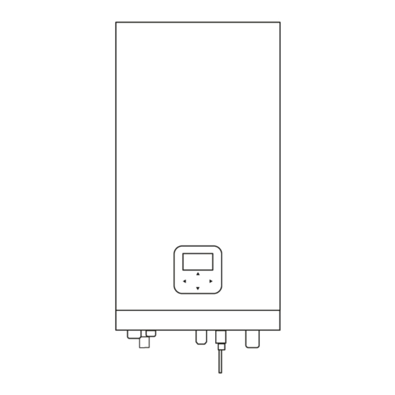
4 INSTALLATION PRECAUTIONS 4.1 Dimensions Dimensions of the wall bracket: 3× 12 unit:mm Fig.4-1 Dimensions of the unit: Fig.4-2 unit:mm NAME Refrigerant gas connection5/8"-14UNF Refrigerant gas connection 5/8"-14UNF Refrigerant liquid connection 1/4"(60) or 3/8"(100/160) -14UNF Drainage Water Inlet R1” Water Outlet R1” 4.2 Installation requirements The indoor unit is packed in a box. -
Page 90: Servicing Space Requirements
WARNING Do not grasp the control box or pipe to lift the unit! Fig.4-3 4.3 Servicing space requirements ≥300 ≥350 ≥500 Fig.4-4 unit:mm... -
Page 91: Mounting The Indoor Unit
Mounting the indoor unit Fix the wall mounting bracket to the wall using appropriate plugs and screws. Make sure the wall mounting bracket is horizontal level. Pay special attention to prevent overflow of the drain pan. Hang the indoor unit on the wall mounting bracket. two persons two persons two persons... -
Page 92: General Introduction
5 GENERAL INTRODUCTION These units are used for both heating and cooling applications and domestic hot water tanks.They can be combined with fan coil units, floor heating applications, low temperature high efficiency radiators, domestic hot water tanks (field supply) and solar kits (field supply). -
Page 93: Accessories
In cooling mode, the lowest outlet water temperature 6 ACCESSORIES (T1stopc) that the unit can reach in different outdoor temperature(T4) is listed below: Installation Fittings Quantity Shape Name ETHKH06A ETHKH10A ETHKH16A Installation and owner’s manual(this book) Operation manual M16 Copper Nut Tamper M9 Copper Nut Tamper Operation range by heat pump with possible limitation and protection. -
Page 94: Typical Applications
7 TYPICAL APPLICATIONS The application examples given below are for illustration only. 7.1 Application 1 Indoor Outdoor 2.11 FHL1 FHL2 FHLn 2.10 14.2 14.1 Modbus 14.3 Code Assembly unit Code Assembly unit Outdoor unit Expansion vessel (Field supply) Hydraulic module Domestic hot water tank (Field supply) User interface 14.1... - Page 95 Space heating The ON/OFF signal and operation mode and temperature setting are set on the user interface. P_o(6) keeps running as long as the unit is ON for space heating, SV1(4) keeps OFF. Domestic water heating The ON/OFF signal and target tank water temperature (T5S) are set on the user interface. P_o(6) stops running as long as the unit is ON for domestic water heating, SV1(4) keeps ON.
-
Page 96: Application
7.2 Application 2 ROOM THERMOSTAT Control for Space heating or cooling need to be set on the user interface. It can be set in three ways: MODE SET/ONE ZONE/DOUBLE ZONE. The indoor unit can be connected to a high voltage room thermostat and a low voltage room thermostat. - Page 97 7.2.2 Mode set control Indoor Outdoor FCU1 FCU2 FCUn 2.11 2.10 FHL1 FHL2 FHLn Modbus Coding Assembly unit Coding Assembly unit Outdoor unit Shut-off valve (Field supply) Indoor unit Filling valve (Field supply) User interface Drainage valve (Field supply) Balance tank (Field supply) Collector/distributor (Field supply) Automatic bleed valve Bypass valve (Field supply)
- Page 98 7.2.3 Double zone control Indoor Outdoor RAD.1 ZONE1 2.11 RAD.2 2.10 RAD.n ZONE2 8.1 8.2 FHL1 FHL2 FHLn Modbus Coding Assembly unit Coding Assembly unit Outdoor unit Filter (Accessory) Indoor unit Shut-off valve (Field supply) User interface Filling valve (Field supply) Balance tank (Field supply) Drainage valve (Field supply) Automatic bleed valve...
- Page 99 The floor heating loops require a lower water temperature in heating mode compared to radiators or fan coil units. To achieve these two set points, a mixing station is used to adapt the water temperature according to requirements of the floor heating loops. The radiators are directly connected to the unit water circuit and the floor heating loops are after the mixing station.
-
Page 100: Overview Of The Unit
8 OVERVIEW OF THE UNIT 8.1 Disassembling the unit The indoor unit cover can be removed by removing the 2 screws and unhitching the cover. CAUTION Make sure to fix the cover with the screws and nylon washers when installing the cover (screws are delivered as accessory) .Parts inside the unit can be hot. - Page 101 14.2 14.2 14.1 14.1 Basic Customized Coding Assembly unit Explaination Remaining air in the water circuit will be automatically removed Automatic bleed valve via the automatic bleed valve. Expansion vessel (8 L) Refrigerant gas pipe Refrigerant liquid pipe Four temperature sensors determine the water and refrigerant Temperature sensors temperature at various points.
-
Page 102: Electronic Control Box
8.3 Electronic control box PCB of indoor unit Customized Basic Note:The picture is only for reference, please refer to the actual product. - Page 103 8.3.1 Main control board of indoor unit Order Assembly unit Order Assembly unit Port Code Port Code M1 M2 CN21 POWER Port for power supply Port for remote switch CN36 Port for temperature board T1 T2 Rotary dip switch Communicate port between indoor unit and Digital display DIS1 CN19...
-
Page 104: Refrigerant Pipework
8.4 Refrigerant pipework For all guidelines, instructions and specifications regarding refrigerant pipework between the indoor unit and outdoor unit, please refer to "Installation and owner’s manual (M-thermal split outdoor unit)". CAUTION When connecting the refrigerant pipes, always use two wrenches/spanners for tightening or loosening nuts! Failure to do so can result in damaged piping connections and leaks. - Page 105 8.5.1 Check the water circuit The unit is equipped with a water inlet and water outlet for connection to a water circuit. This circuit must be provided by a licensed technician and must comply with local laws and regulations. The unit is only to be used in a closed water system. Application in an open water circuit can lead to excessive corrosion of the water piping.
- Page 106 Before continuing installation of the unit, check the following: The maximum water pressure ≤ 3 bar. The maximum water temperature ≤ 70°C according to safety device setting. Always use materials that are compatible with the water used in the system and with the materials used in the unit. Ensure that components installed in the field piping can withstand the water pressure and temperature.
- Page 107 8.5.3 Water circuit connection Water connections must be made correctly in accordance with labels on the indoor unit, with respect to the water inlet and water outlet. CAUTION Be careful not to deform the unit’s piping by using excessive force when connecting the piping. Deforming the piping can cause the unit to malfunction.
-
Page 108: Filling Water
Water may enter into the flow switch and cannot be drained out and may freeze when the temperature is low enough. The flow switch should be removed and dried, then can be reinstalled in the unit. There need drying NOTE 1.Counterclockwise rotation, remove the flow switch. -
Page 109: Water Piping Insulation
8.7 Water piping insulation The complete water circuit including all piping, water piping must be insulated to prevent condensation during cooling operation and reduction of the heating and cooling capacity as well as prevention of freezing of the outside water piping during winter. The insulation material should at least of B1 fire resistance rating and complies with all applicable legislation. - Page 110 AHS1 AHS2 1OFF 2OFF DFT2 DFT1 IBH1 3OFF CN11 CN30 25 T Outdoor Indoor Modbus Coding Assembly unit Coding Assembly unit Outdoor unit SV2: 3-way valve (field supply) SV1: 3-way valve for domestic hot Solar energy kit (field supply) water tank (field supply) Booster heater User interface High voltage room thermostat (field supply)
- Page 111 Description AC/DC Required number of conductors Maximum running current Item Solar energy kit signal cable 200mA User interface cable 200mA Room thermostat cable 200mA(a) Solar pump control cable 200mA(a) Outside circulation pump control cable 200mA(a) 200mA(a) DHW pump control cable SV2: 3-way valve control cable 200mA(a) SV1: 3-way valve control cable...
- Page 112 Use the correct screwdriver to tighten the terminal screws. Small screwdrivers can damage the screw head and prevent appropriate tightening. Over-tightening the terminal screws can damage the screws. Attach a ground fault circuit interrupter and fuse to the power supply line. In wiring, make certain that prescribed wires are used, carry out complete connections, and fix the wires so that outside force cannot affect the terminals.
- Page 113 L2 L3 INDOOR UNIT INDOOR UNIT INDOOR UNIT POWER SUPPLY POWER SUPPLY POWER SUPPLY (Basic) 1-phase 3KW backup heater 3-phase 3/6/9KW backup heater Stated values are maximum values (see electrical data for exact values). CAUTION When connecting to the power supply terminal, use the circular wiring terminal with the insulation casing (see Figure 8.1). Use power cord that conforms to the specifications and connect the power cord firmly.
- Page 114 8.8.6 Connection for other components Unit 4-16kw P_c P_o P_s P_d AHS1 AHS2 1OFF 2OFF IBH1 N 3ON DFT2 DFT1 3OFF CN11 CN30 Code Code Print Print Connect to Connect to Solar energy input signal Wired controller Room thermostat input high voltage CN30 Outdoor unit...
- Page 115 1) For solar energy input signal 25 26 27 28 1 2 3 4 5 1 2 3 4 5 6 7 8 9 10 11 12 29 30 31 32 1 2 3 4 5 6 7 8 9 10 13 14 15 16 17 6 7 8 9 10 CN30...
- Page 116 4) For remote shut down: 25 26 27 28 1 2 3 4 5 29 30 31 32 6 7 8 9 10 CN11 CN30 CLOSE: SHUT DOWN 5) For Pumpc and DHW pipe pump : 25 26 27 28 1 2 3 4 5 29 30 31 32 6 7 8 9 10...
- Page 117 Voltage 220-240VAC Maximum running current(A) Wiring size(mm 0.75 25 26 27 28 1 2 3 4 5 29 30 31 32 6 7 8 9 10 Control port signal type Type 2 CN11 CN30 a) Procedure Connect the cable to the appropriate terminals as shown in the picture.
- Page 118 Room thermostat type2 (Low voltage): HEAT(HT) COM COOL(CL) HEAT(HT) COOL(CL) Method A Method C (Mode set control) (Double zone control) POWER POWER IN POWER IN zone1 zone2 There are three methods for connecting the thermostat cable (as described in the picture above) and it depends on the application.
- Page 119 C.2 When unit detect voltage is 12VDC between CL and COM, 8) For additional heat source control: zone2 turn on according to climate temp curve. When unit detect voltage is 0V between CL and COM, zone2 turn off. C.3 When HT-COM and CL-COM are detected as 0VDC, unit turn off.
- Page 120 Voltage 220-240VAC Maximum running current(A) Wiring size(mm 0.75 Control port signal type 25 26 27 28 Type 1 1 2 3 4 5 29 30 31 32 6 7 8 9 10 CN11 CN30 10) For outside circulation pump P_o: 25 26 27 28 1 2 3 4 5...
-
Page 121: Start-Up And Configuration
1. when EVU signal is on, the unit operate as below: 2. When EVU signal is off, and SG signal is on, the unit operate normally. DHW mode turn on, the setting temperature will be changed to 70 3. When EVU signal is off, SG signal is off, the DHW mode is off, and automatically, and the TBH operate as below:T5<69. -
Page 122: Dip Switch Settings Overview
Temperature curves for cooling mode - 10≤ T4 15 15≤ T4 22 22≤ T4 30 30≤ T4 1- T1S 2- T1S 3- T1S 4- T1S 5- T1S 6- T1S 7- T1S 8- T1S - 10≤ T4 15 15≤ T4 22 22≤... -
Page 123: Initial Start-Up At Low Outdoor Ambient Temperature
Factory Factory Factory ON=1 ON=1 OFF=0 OFF=0 ON=1 OFF=0 switch switch switch defaluts defaluts defaluts Start pumpo after Start pumpo after 0/0=3kW IBH(One-stage control) Reserved Reserved six hours will six hours will 0/1=6kW IBH(Two-stage control) be invalid be valid 1/1=9kW IBH(Three-stage OFF/OFF control) without TBH... -
Page 124: Setting The Pump
9.5 Setting the pump The pump is contolled via a digital low-voltage pulse-width modulation signal which means that the speed of rotation depends on the input signal.The speed changes as a function of the input profile. The relationships between the head and the water flow rated,the PMW Return and the water flow rated are shown in the graph below. - Page 125 Indoor unit ETHKH16A...
-
Page 126: Field Settings
CAUTION If the valves are at the incorrect position, the circulation pump will be damaged. DANGER If it's necessary to check the running status of the pump when unit power on, please do not touch the internal electronic control box components to avoid electric shock. Failure diagnosis at first installation If nothing is displayed on the user interface, it is necessary to check for any of the following abnormalities before diagnosing possible error codes. - Page 127 About FOR SERVICEMAN 9.6.1 DHW MODE SETTING "FOR SERVICEMAN" is designed for the installer to set DHW = domestic hot water the parameters. Go to MENU> FOR SERVICEMAN> 1.DHW MODE SETTING. Press OK. The following pages will be Setting the composition of equipment. displayed: Setting the parameters.
- Page 128 9.6.5 TEMP. TYPE SETTING 2 COOL MODE SETTING About TEMP. TYPE SETTING 2.1 COOL MODE 2.2 t_T4_FRESH_C 2.0HRS The TEMP. TYPE SETTING is used for selecting whether 2.3 T4CMAX 43°C the water flow temperature or room temperature is used 2.4 T4CMIN 20°C to control the ON/OFF of the heat pump.
- Page 129 9.6.7 Other HEATING SOURCE In this case, the setting value of zone 1 is T1S,the setting value of zone 2 is T1S2. The OTHER HEATING SOURCE is used to set the parameters of the backup heater, additional heating If you set DOUBLE ZONE and ROOM TEMP. to YES, sources and solar energy kit.
- Page 130 9 SERVICE CALL If YES is selected, the following pages will be displayed: PHONE NO. 33512345678 MOBILE NO. 8613929145152 11 TEST RUN 11.1 POINT CHECK 11.2 AIR PURGE 11.3 CIRCULATION PUMP RUNNING CONFIRM ADJUST 11.4 COOL MODE RUNNING 11.5 HEAT MODE RUNNING The number displayed on the user interface is the phone ENTER number of your local dealer.
- Page 131 When in air purge mode, SV1 will open, SV2 will close. During HEAT MODE test running, the default target outlet 60s later the pump in the unit (PUMPI) will operate for water temperature is 35°C. The IBH (internal backup 10min during which the flow switch will not work. After the heater) will turn on after the compressor runs for 10 min.
- Page 132 Go to MENU> FOR SERVICEMAN> 12.SPECIAL During preheating for floor, all the buttons except OK are FUNCTION. invalid. If you want to turn off the preheating for floor, please press OK. Before floor heating, if a large amount of water remains on the floor, the floor may be warped or even rupture during The following page will be displayed: floor heating operation, in order to protect the floor, floor...
- Page 133 When the cursor is on OPERATE FLOOR DRYING,use Go to MENU> FOR SERVICEMAN>13.AUTO RESTART to scroll to YES and press OK. The following page will be displayed: 13 AUTO RESTART 12.2 FLOOR DRYING UP 13.1 COOL/HEAT MODE DO YOU WANT TO TURN OFF THE 13.2 DHW MODE FLOOR DRYING UP FUNCTION? ADJUST...
- Page 134 9.6.16 Setting parameters The parameters related to this chapter are shown in the table below. Setting Order number Code State Default Minumum Maximum Unit interval DHW MODE Enable or disable the DHW mode:0=NON,1=YES DISINFECT Enable or disable the disinfect mode:0=NON,1=YES DHW PRIORITY Enable or disable the DHW priority mode:0=NON,1=YES DHW PUMP...
- Page 135 HEAT MODE Enable or disable the heating mode The refresh time of climate related curves for heating t_T4_FRESH_H hours mode The maximum ambient operating temperature for heating T4HMAX mode The minimum ambient operating temperature for heating T4HMIN mode dT1SH The temperature difference for starting the unit (T1) The temperature difference for starting the unit (Ta) dTSH The setting temperature 1 of climate related curves for...
- Page 136 12.4 t_DRYUP The day for w arming up during floor drying up The continue days in high temperature during floor 12.5 t_HIGHPEAK drying up The day of dropping temperature during floor drying 12.6 t_DRYD The target peak temperature of w ater flow during 12.7 T_DRYPEAK °C...
-
Page 137: Test Run And Final Checks
10 TEST RUN AND FINAL The following checks must be performed at least once a year by qualified person. CHECKS Water pressure Check the water pressure, if it is below 1 bar,fill water The installer is obliged to verify correct operation of unit to the system. -
Page 138: Trouble Shooting
12 TROUBLE SHOOTING This section provides useful information for diagnosing and correcting certain troubles which may occur in the unit. This troubleshooting and related corrective actions may only be carried out by your local technician. 12.1 General guidelines Before starting the troubleshooting procedure, carry out a thorough visual inspection of the unit and look for obvious defects such as loose connections or defective wiring. - Page 139 Symptom 3: Pump is making noise (cavitation) POSSIBLE CAUSES CORRECTIVE ACTION There is air in the system. Purge air. • Check on the manometer that there is sufficient water pressure. The water pressure must be > 1 bar (water is cold). •...
-
Page 140: Operation Parameter
Symptom 8: DHW mode can’t change to Heat mode immediately POSSIBLE CAUSES CORRECTIVE ACTION • Set "t_DHWHP_MAX" to minimum value, the suggested value is 60min. • If circulating pump out of unit is not controlled by unit, try to Heat exchanger for space connect it to the unit. - Page 141 OPERATION PARAMETER OPERATION PARAMETER OPERATION PARAMETER FAN SPEED 600R/MIN TW_O PLATE W-OUTLET TEMP. 35°C T3 OUTDOOR EXCHARGE TEMP. 5°C IDU TARGET FREQUENCY 46Hz TW_I PLATE W-INLET TEMP. 30°C T4 OUTDOOR AIR TEMP. 5°C FREQUENCY LIMITED TYPE T2 PLATE F-OUT TEMP. 35°C TF MODULE TEMP.
-
Page 142: Error Codes
12.4 Error codes When a safety device is activated, an error code will be displayed on the user interface. A list of all errors and corrective actions can be found in the table below. Reset the safety by turning the unit OFF and back ON. In case this procedure for resetting the safety is not successful, contact your local dealer. - Page 143 ERROR MALFUNCTION FAILURE CAUSE CODE OR PROTECTION AND CORRECTIVE ACTION 1. The EEprom parameter is error, rewrite the EEprom data. 2. EEprom chip part is broken, change a new EEprom chip Indoor unit EEprom failure part. 3. main control board of indoor unit is broken, change a new PCB.
- Page 144 ERROR MALFUNCTION FAILURE CAUSE CODE OR PROTECTION AND CORRECTIVE ACTION Three times “PP” The same to "PP". protection and Tw_out< "1.Check the resistance of the sensor. 2.The Tbt1 sensor connector is loosen,reconnect it. Buffer tank up 3.The Tbt1 sensor connector is wet or there is water in,remove temp.sensor(Tbt1) fault the water ,make the connector dry.Add waterproof adhesive.
-
Page 145: Technical Specifications
13 TECHNICAL SPECIFICATIONS ETHKH06A Indoor unit model ETHKH10A ETHKH16A 220-240V~ 50Hz Power supply Rated input 0.4A 0.4A 0.4A Rated Current Refer to the technical data Norminal capacity 420x790x270 Dimensions (W×H×D)[mm] 525x1050x360 Packing (W×H×D)[mm] Plate heat exchanger Heat exchanger Electric heater 5.0L Internal water volume 0.3MPa... - Page 146 Indoor unit model 06 (3kW Heater) 10 (3kW Heater) 16 (3kW Heater) 06 (9kW Heater) 10 (9kW Heater) 16 (9kW Heater) 220-240V~ 50Hz 380~415V 3N~ 50Hz Power supply 3095W 3095W 3095W 9095W 9095W 9095W Rated input 13.5A 13.5A 13.5A 13.3A 13.3A 13.3A Rated Current...
-
Page 147: Information Servicing
14 INFORMATION SERVICING 1) Checks to the area Prior to beginning work on systems containing flammable refrigerants, safety checks are necessary to ensure that the risk of ignition is minmised. For repair to the refrigerating system, the following precautions shall be complied with prior to conducting work on the system. - Page 148 10) Repairs to sealed components a) During repairs to sealed components, all electrical supplies shall be disconnected from the equipment being worked upon prior to any removal of sealed covers, etc. If it is absolutely necessary to have an electrical supply to equipment during servicing, then a permanently operating form of leak detection shall be located at the most critical point to warn of a potentially hazardous situation.
- Page 149 Ensure that contamination of different refrigerants does not occur when using charging equipment. Hoses or lines shall be as short as possible to minimize the amount of refrigerant contained in them. Cylinders shall be kept upright. Ensure that the refrigeration system is earthed prior to charging the system with refrigerant. Label the system when charging is complete(if not already).
- Page 150 ANNEX A: Refrigerant cycle Basic Customized Description Description Item Item Water Side Heat Exchanger Expansion vessel (Plate Heat Exchange) Circulating pump Flow switch Manometer Refrigerant liquid line temperature sensor Safety valve Refrigerant gas line temperature sensor Internal backup heater Water outlet temperature sensor Total outlet temperature sensor Water inlet temperature sensor Automatic bleed valve...
- Page 151 Water quality requirements on the circuit Water quality must meet the standards of European Directive 98/83 EC and the criteria set out in UNE 112.076. Water quality should be analysed before use; to evaluate criteria such as concentration, pH value, conductivity, chloride ion concentration (Cl-), sulfide ion concentration (S2-), etc.
-
Page 152: Guarantee Conditions
WARRANTY CONDITIONS EAS ELECTRIC offers a repair guarantee against all manufacturing defects, including labour and spare parts, within the terms and conditions indicated below: 3 years: Domestic Range, Commercial Range, Domestic VRF, M-Thermal Monoblock and Biblock, Domestic Fan Coils, DHW aerothermal storage heaters, Swimming Pool Heat Pumps, Domestic Minichillers, Compact solar heaters, Thermosiphons, Purifiers, Dehumidifiers and other air treatment appliances. - Page 153 The european directive 2012/19 /UE on wasted electrical and electronic equipments (WEEE), requires that household electrical appliances must not be disposed of in the normal unsorted municipal waste stream. appliances must be collected separately in order to optimize the recovery and recycling of the materials they contain, and reduce the impact on human health and the environment.
- Page 154 Toda la documentación del producto Complete documents about the product Documentation plus complète sur le produit Mais documentação do produto 16125300A12108 V1.0 EAS ELECTRIC SMART TECHNOLOGY, S.L.U. P.I. San Carlos, Camino de la Sierra, S/N, Parcela 11 03370 Redován (Alicante) - ESPAÑA...