
Related Manuals for EAS Electric ETH-4VB


Summary of Contents for EAS Electric ETH-4VB
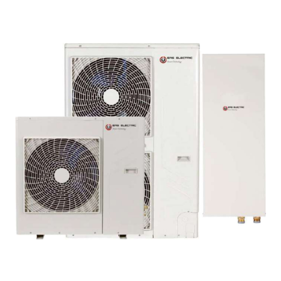
- Page 1 EAS THERMAL BIBLOCK MANUAL DE INSTALACIÓN Y MANUAL DE USUARIO MODELOS: ETH-10VB ETH-12VB ETH-16VB...
-
Page 2: Table Of Contents
PRECAUCIÓN CONTENIDOS PÁGINA Nueva instalación de bomba de calor refrigerante 1. PRECAUCIONES................1 ESTA BOMBA DE CALOR ADOPTA AL NUEVO 2. ACCESORIOS Y REFRIGERANTE..........2 REFRIGERANTE HFC (R410A) QUE NO DESTRUYE LA 3. ANTES DE LA INSTALACION............2 CAPA DE OZONO. 4. INFORMACIÓN IMPORTANTE SOBRE EL REFRIGERANTE ●... -
Page 3: Accesorios Y Refrigerante
Herramientas necesarias para el trabajo de instalación: ● No modifique esta unidad retirando ninguno de los Destornillador guardas de seguridad ni pasando ninguno de los Colector de calibre Corona pared(65mm) (Manguera de carga: R410A interruptores de bloqueo de seguridad. La exposición de requisito especial) la unidad al agua u otra humedad antes de la instalación Llave... -
Page 4: Utilizado
INFORMACIÓN IMPORTANTE CON RESPECTO Asegúrese de que hay suficiente espacio para hacer la instalación AL REFRIGERANTE UTILIZADO ■ Coloque el lado de salida en ángulo recto con respecto a la dirección del viento. Este producto contiene gases fluorados de efecto invernadero cubiertos por el Protocolo de Kyoto. -
Page 5: Instalacion De Unidad Exterior
6 INSTALACIÓN DE UNIDAD EXTERIOR 6.1 Lugar de instalación Por favor, manténgase alejado del siguiente lugar, ya que se puede producir un mal funcionamiento de la máquina: 1) Hay fugas de gas combustible. 2) Hay mucho aceite (incluido el aceite del motor) ingrediente. 3) Hay aire salado que rodea (cerca de la costa) 4) Hay gas cáustico (el sulfuro, por ejemplo) que existe en el aire (cerca de una fuente termal) - Page 6 2) En paralelo conecte las dos unidades o superior. >300 >600 >2000 Fig.6-6 3) Paralelo conecte la parte frontal con laterales traseros >2000 >500 >3000 >3000 >300 6.4 Salida de agua La siguiente figura muestra cuatro salidas de agua condensada en el chasis para la selección: Fig.6-7 6.3 Mudanza e instalación Dado que el centro de gravedad de la unidad no está...
-
Page 7: Instalar El Tubo De Conexión
7 INSTALAR EL TUBO DE CONEXIÓN Tubería más gruesa Verifique si la diferencia de altura entre la unidad interior y la unidad exterior, la longitud de la tubería de refrigerante y el número de curvas cumplen los siguientes requisitos: 7.1 Tubería de refrigerante Tubo de salida frontal Tubo de salida lateral Tubo de superficie... - Page 8 7.5 Eliminar la suciedad o el agua en las tuberías 1) Asegúrese de que no haya suciedad ni agua antes de conectar la 7.4 Método de conexión tubería a las unidades exteriores. 2) Lave las tuberías con nitrógeno a alta presión, nunca use refrigerante de la unidad exterior.
-
Page 9: Cableado Eléctrico
8 CABLEADO ELÉCTRICO Unid. exterior PRECAUCIÓN ● Seleccione la fuente de alimentación para la unidad interior y 3x0.75mm Alimentacion 3x4.0mm (3-apantallado) la unidad exterior respectivamente. Alimentacion ● La fuente de alimentación tiene un circuito derivado específico 3x2.5mm con protector de fugas y un interruptor manual. ●... - Page 10 8.3 Componentes principales de la caja de interruptores La imagen que se muestra aquí es solo indicativa. Si hay inconsistencia entre la imagen y el producto real, el producto real deberá regir. 8.3.1 Componentes principales de la caja de interruptores (1-fase,10/12/14/16kW) 1-phase 10~16kW PCB A 5 4 3 10 Puerto de entrada N para el módulo Pfc (VIN-N)
-
Page 11: Funcionamiento De Prueba
1-phase 10~16kW PCB B 14 13 17 Puerto de fuente de alimentación para 1 Puerto para interruptor de presión (CN12) 7 Reservados (CN30) ventilador (CN18) 8 Puertos para el valor de la expansión 2 Puertos para sensor de temperatura de 18 Puerto para ventilador de bajada (CN19) eléctrica (CN22) succión (CN24) -
Page 12: Entrega Del Manual Al Cliente
ADVERTENCIA Solicite a su distribuidor la instalación de la bomba de calor. La instalación incompleta realizada por usted mismo puede provocar una fuga de agua, una descarga eléctrica y un incendio. Pregunte a su distribuidor por mejoras, reparaciones y mantenimiento. Unidad exterior Unidad interior La mejora, reparación y mantenimiento incompletos... - Page 13 Si el refrigerante gotea en la habitación, el contacto con el Nunca exponga a los niños pequeños, plantas o fuego de un quemador, un calentador o una cocina puede animales directamente al flujo de aire. producir un gas dañino. Influencia adversa para niños pequeños, animales y plantas Apague todos los dispositivos de calefacción combustibles, puede resultar.
-
Page 14: Exterior
13 CÓDIGO DE MAL FUNCIONAMIENTO ● Mal manejo en funcionamiento: ● Si se produce una manipulación incorrecta debido a la DE UNIDAD EXTERIOR iluminación o la conexión inalámbrica móvil, apague el interruptor de alimentación manual y vuelva a encenderlo, luego presione el botón ON / OFF. - Page 15 Código Descripción Solución Verifique que la unidad esté funcionando dentro de El modo de calefacción del ventilador su rango de operación, contacte a su distribuidor funciona en la región A durante 10 minutos. local Reinicie la unidad, si el error vuelve a ocurrir, Dos veces H6 en 10 minutos póngase en contacto con su distribuidor local.
-
Page 16: Solución De Problemas
14 LOS SÍNTOMAS SIGUIENTES NO 15 SOLUCIÓN DE PROBLEMAS SON PROBLEMAS DE BOMBA DE CALOR Si ocurre uno de los siguientes fallos de funcionamiento, detenga la operación, apague la alimentación y póngase en Síntoma 1: el sistema no funciona contacto con su distribuidor. La bomba de calor no arranca inmediatamente después de La lámpara de operación parpadea rápidamente (dos veces por presionar el botón de ENCENDIDO / APAGADO en el... - Page 17 Síntomas Causas Solución Fallo de alimentación. Espera el regreso del poder. El interruptor de encendido está apagado. Encienda el poder. La unidad no arranca. El fusible del interruptor de alimentación Replicación: puede haberse quemado. Pilas del mando Reemplace las baterías o revise el a distancia agotadas u otro problema del controlador.
-
Page 18: Especificaciones Tecnicas
16 Especificaciones técnicas ETH-10VB ETH-12VB Modelo(Capacity mark) ETH-16VB 220-240V~ 50Hz Alimentacion Entrada de potencia nominal 6.0kW Corriente nominal 27.0A Capacidad Nominal Diríjase a los datos técnicos Dimensiones (W×H×D)[mm] 900*1327*400 Embalaje (W×H×D)[mm] 1030×1456×435 DC motor / Horizontal Motor ventilador Compresor DC inverter dual rotary Intercambiador de calor Fin-coil Refrigerante... -
Page 19: Información Importante Para El Refrigerante Usado
17 INFORMACIÓN IMPORTANTE POR EL REFRIGERANTE USADO Este producto tiene el gas fluorado que figura en el protocolo de kyoto y está prohibido emitir al aire. Tipo de refrigerante: R410A; Volumen de GWP: 2088; GWP = Potencial de calentamiento global Carga de fábrica Modelo Refrigerante/kg... - Page 20 Requisitos de calidad del agua en el circuito La calidad del agua debe cumplir los estándares de la Directiva Europea 98/83 CE y los criterios indicados en la Norma UNE 112.076 Antes de conectar la unidad exterior: En las instalaciones tanto nuevas como ya existentes, se debe de realizar una limpieza a fondo de las tuberías utilizando un producto de limpieza químico adecuado, posteriormente se lavarán las tuberías para limpiar el agente químico.
- Page 21 CONTROL POR CABLE CON PROGRAMACIÓN SEMANAL MANUAL DE INSTALACIÓN Y MANUAL DE USUARIO MODELO: ECRTH...
- Page 22 PRECAUCIONES GENERALES DE Este manual ofrece una descripción detallada de las precauciones que se han de tener en cuenta durante el SEGURIDAD funcionamiento del equipo. 1.1 Acerca de la documentación Para asegurar el buen desempeño del control remoto cableado Las precauciones descritas en este documento cubren temas muy importantes, lea detenidamente.
- Page 23 Ó INFORMACIÓN SOBRE EL PANEL DE CONTROL 2.1 Control cableado Introduzca la selección del Encender o apagar el modo calefacción menú desde la página de /refrigeración o el modo ACS (DHW) en el menú. inicio. Navegador del cursor en la pantalla/ navegador para las opciones del menú...
- Page 24 USO DE LAS PÁGINAS DE INICIO 3.1 Descripción de las páginas de inicio Se pueden usar las páginas de inicio para leer y cambiar los ajustes diariamente. Lo que se puede ver y hacer en las páginas de inicio está descrito donde se aplica.
- Page 25 Climatización (controlada por temperatura de agua / panel de control) En ajustes iniciales, ir a "FOR SERVICEMAN / TEMP. TYPE SETTING" (ver AJUSTE TIPO CONTROL TEMP. en el manual de la unidad interior o monobloc) y ajustar "TEMP. TYPE SETTING" de la siguiente forma: "WATER FLOW TEMP."...
- Page 26 4.2 Acceder a las opciones del menú Desde una página principal, pulsar "MENU". Resultado: Se visualiza la estructura del menú: 21: 55 08 - 08 - 2015 SAT. TANK 21: 55 08 - 08 - 2015 SAT. 55 C TANK 5.2 Encendido / Apagado (ON/OFF) Use el panel de control para encender o apagar la unidad en calefacción o refrigeración.
- Page 27 Si "DUAL ROOM THERMOSTAT" (termostato ambiente doble) está en "YES" (ver TERMOSTATO AMBIENTE en el manual de la unidad interior o monobloc). Si el termostato de refrigeración está apagado, el 21: 55 08 - 08 - 2015 SAT. de calefacción está encendido y la unidad está funcionando, pero la pantalla está...
- Page 28 5.4 Ajuste del modo de funcionamiento para climatización Si el cursor está en la temperatura, use '' '' '' '' para seleccionar y use '' '' '' '' para ajustar la temperatura. Ajuste del modo de funcionamiento mediante el panel de control. Vaya a ''MENU'' >...
- Page 29 Use '' '' '' '' '' '' '' '' para moverse y use '' '' '' '' para ajustar 6 MENU el tiempo y la temperatura. 6.1 "OPERATION MODE" (Modo de funcionamiento) Se pueden ajustar seis períodos y seis temperaturas. Por ejemplo: Ahora son las 8:00 y hay una temp.
- Page 30 6.2.3 "ECO MODE" (Modo Económico) INFORMACIÓN El "ECO MODE" se usa para ahorrar energía durante la noche. "WEATHER TEMP. SET" tiene 4 tipos de curvas: 1. la curva de Si el "ECO MODE" está activo, se muestra en la página de ajuste a alta temperatura para calefacción, 2.
- Page 31 Use '' '' '' '' para moverse y use '' '' '' '' para ajustar la hora. Pulse ''OK'' o la tecla '' '' para ajustar la hora. Aparecerá la página: INFORMACIÓN PRESET TEMPERATURE Si "CURRENT STATE" está en "ON" y "ECO TIMER" está en "OFF", sale del "ECO MODE"...
- Page 32 Use '' '' '' '' '' '' '' '' para moverse y use '' '' '' '' para ajustar los PRESET TEMPERATURE parámetros al ajustar ''OPERATE DAY'' y ''START''. Si "OPERATE DAY" se ajusta en "FRI" (Viernes) y el "START" (encendido) se ajusta a las 23:00, la función de desinfección se activará...
- Page 33 DOMESTIC HOT WATER DHW DOMESTIC HOT WATER DHW DOMESTIC HOT WATER DHW DOMESTIC HOT WATER DHW Moverse a “ ” pulsar '' OK '' para seleccionar o eliminar. se ha cancelado se ha seleccionado el temporizador, el temporizador). Use las teclas '' '' '' '' '' '' '' '' para moverse y use '' '' '' '' Use ''ON/OFF'' para seleccionar "ON"...
- Page 34 Ejemplo: 6.4.1 "TIMER" (Temporizador diario) Si la función "WEEKLY SCHEDULE" (prog. semanal) está Ajuste de los seis temporizadores: activada, el "TIMER" no será efectivo, siempre el último ajuste será el efectivo. Si el "TIMER" esta activado, se muestra el icono en la página principal.
- Page 35 SCHEDULE INFORMACIÓN Si se cambia de la configuración principal (MAIN page) a la configuración de habitación (ROOM page) o viceversa, hay que reestablecer el temporizador y el programador semanal. Si se realiza alguna modificación de los parámetros en el termostato de habitación (ROOM THERMOSTAT) no se aplicará...
- Page 36 6.5 "OPTIONS" (Opciones) Puede usar '' '' '' '' para seleccionar el nivel 1 ó 2. Pulse ''OK''. Si se selecciona "TIMER", pulse "OK" para acceder, aparecerá la El menú de "OPTIONS" consta de: siguiente página. 1) "SILENT MODE" función silencio. 2) "HOLIDAY AWAY"...
- Page 37 2) Activar el modo de vacaciones fuera. Antes y después de sus vacaciones, se usará su programación Vaya a ''MENU'' > ''OPTIONS'' > ''HOLIDAY AWAY''. Pulse "OK". normal. Durante sus vacaciones, puede ahorrar energía y evitar que se Use ''ON/OFF'' para seleccionar ''OFF'' u ''ON'' y use le enfríe la casa.
- Page 38 La contraseña es 123. Usar para moverse y para ajustar el valor numerico. Pulsar "OK". aparecerá la página siguiente: CHILD LOCK Pulse "OK" para mostrar el significado del código de error. Use '' '' '' '' para moverse y ''UNLOCK'' para seleccionar "LOCK" o "UNLOCK".
- Page 39 6.8 "OPERATION PARAMETER" (Parámetros de funcionamiento) INFORMACIÓN Este menú es para que el instalador o el ingeniero de mantenimiento puedan revisar los parámetros de funcionamiento. El parámetro de consumo de corriente es orientativo. Si algunos parámetros no están activados en el sistema, el parámetro que se mostrará...
- Page 40 7 ESTRUCTURA DEL MENÚ : Sumario MENU OPERATION MODE ECO MODE OPERATION MODE HEAT CURRENT STATE PRESET TEMPERATURE COOL ECO TIMER DOMESTIC HOT WATER(DHW) AUTO STATE SCHEDULE PRESET TEMPERATURE OPTIONS PRESET TEMP. CHILD LOCK COMFORT MODE WEATHER TEMP. SET SERVICE INFORMATION CURRENT STATE ECO MODE OPERATION PARAMETER...
- Page 41 1 DHW MODE SETTING FOR SERVICEMAN 1.1 DHW MODE 1.1 DHW MODE 1 DHW MODE SETTING dT5_ON 1.2 TANK HEATER 2 COOL MODE SETTING 1.3 DISINFECT dT1S5 3 HEAT MODE SETTING 1.4 DHW PRIORITY T4DHWMAX 4 AUTO MODE SETTING 1.5 DHW PUMP T4DHWMIN 5 TEMP.
- Page 42 Tabla 1 Curva de temperatura ambiente en el ajuste de baja temperatura para calefacción Tabla 2 Curva de temperatura ambiente en el ajuste de alta temperatura para calefacción...
- Page 43 Tabla 3 Curva de temperatura ambiente en el ajuste de baja temperatura para refrigeración Tabla 4 Curva de temperatura ambiente en el ajuste de alta temperatura para refrigeración...
- Page 44 8 MANUAL DE INSTALACIÓN 8.1 Medidas de seguridad Lea cuidadosamente las precauciones de seguridad antes de instalar la unidad. Las indicaciones de seguridad a continuación deben ser cumplidas. Si no hay incidencias durante la prueba de funcionamiento, entregue el manual al usuario.
- Page 45 60mm...
- Page 46 Si el equipo presenta un funcionamiento anormal, por favor, en primer lugar desconecte la fuente de alimentación, y póngase en contacto con nuestro servicio la postventa (SAT). Para consular su servicio técnico más cercano, acceda a la página web: www.easelectric.es...
- Page 47 EAS THERMAL BIBLOCK INSTALLATION'S AND OWNER'S MANUAL MODELS: ETH-10VB ETH-12VB ETH-16VB...
- Page 48 CAUTION CONTENTS PAGE New Refrigerant Heat Pump Installation 1. PRECAUTIONS..................1 2. ACCESSORY AND REFRIGERANT............2 THIS HEAT PUMP ADOPTS THE NEW HFC REFRIGERANT (R410A)WHICH DOES NOT DESTROY OZONE LAYER. 3. BEFORE INSTALLATION..............3 4. IMPORTANT INFORMATION REGARDING ● The characteristics of R410A refrigerant are; easy to THE REFRIGERANT USED...............3 absorb water, oxidizing membrane or oil, and its pressure is approx.1.6 times higher than that of...
-
Page 49: Accessory And Refrigerant
Required tools for installation work: resultingly causes pipe burst and injuries on persons. ● Do not modify this unit by removing any of the safety Screw driver guards or by by-passing any of the safety interlock Gauge manifold Hole core drill(65mm) (Charge hose:R410A special switches. -
Page 50: Before Installation
2 When installing the unit in a place exposed to strong wind, pay 3 BEFORE INSTALLATION special attention to the following. Strong winds of 5 m/sec or more blowing against the unit's air Before installation outlet causes short circuit (suction of discharge air), and this may Be sure to confirm the model name and the serial no. -
Page 51: Outdoor Unit Installation
6 OUTDOOR UNIT INSTALLATION 6.1 Installation place Please keep away from the following place, or malfunction of the machine may be caused: 1) There is combustible gas leakage. 2) There is much oil (including engine oil) ingredient. 3) There is salty air surrounding(near the coast) 4) There is caustic gas (the sulfide, for example) existing in the air (near a hotspring) 5) A place the heat air expelled out from the outdoor unit can reach... - Page 52 2) Parallel connect the two units or above 6.4 Water Outlet Four condensed water outlets on the chassis for selection display as the follow figure: >300 >600 >2000 Fig.6-6 3) Parallel connect the front with rear sides Water Outlet >2000 >500 >3000 >3000...
-
Page 53: Install The Connecting Pipe
7 INSTALL THE CONNECTING PIPE Fat pipe Check whether the differance in height between the indoor unit and outdoor unit, the length of refrigerant pipe, and the number of the bends meet the following requirements: 7.1 Refrigerant piping Front out pipe Side out pipe Undersurface out pipe Back out pipe... - Page 54 7.4 Connecting method 7.5 Remove Dirt or Water in the Pipes 1) Make sure there is no any dirt or water before connectiong the piping to the outdoor units. Outdoor Unit Indoor Unit 2) Wash the pipes with high pressure nitrogen, never use refrigerant of outdoor unit.
-
Page 55: Electrical Wiring
8 ELECTRICAL WIRING Outdoor Unit CAUTION 3x0.75mm Power Supply 3x4.0mm (3-shield wire) ● Please select power source for indoor unit and outdoor unit respectively. Power Supply 3x2.5mm ● The power supply has specified branch circuit with leakage protector and manual switch. Indoor Unit ●... - Page 56 8.3 Switch box main components The image shown here is indicative only. If there is inconsistency between the image and the actual product, the actual product shall govern. 8.3.1 Switch box main components (1-phase 4\6\8kW) 1-phase 4~8kW PCB A To main board (CN101,CN105) Compressor connection port U V W (U,V,W) Input port N for IPM module(N) Input port P for IPM module(P)
- Page 57 1-phase 4~8kW PCB B PCB A Rectifier bridge input port L 10 Th temperature sensor port 2 Hydraulic compartment input port2 11 Pressure sensor port Rectifier bridge input port N 12 Wire controller port Power supply N 13 P/N/+18V port Power supply L 14 To IPDU/PFC Transformer output port...
- Page 58 8.3.2 Switch box main components (1-phase,10/12/14/16kW) 1-phase 10~16kW PCB A Reserved(CN2) Power Supply Of U Phase For Compressor(U) 10 Input Port N For Pfc Module(VIN-N) Input Port N For Ipm Module(N) Output Port N Of Pfc Module(N_1) 11 Input Port P Foripm Modele(P) Power Supply Of W Phase For Output Port P Of Pfc Module(P_1) 12 Communicate Port Between Pcb A...
- Page 59 8.3.2 Switch box main components (1-phase,10/12/14/16kW) 3-phase 12~16kW PCB A 1 Power supply L3(L3) 7 Power supply for main control board(CN19) 2 Power supply L2(L2) 8 Power filtering L1(L1’) 3 Power supply L1(L1) 9 Power filtering L2(L2’) 4 Power supply N(N) 10 Power filtering L3(L3’) 5 Ground wire(GND_1) 11 Ground wire(GND_2)
-
Page 60: Test Running
3-phase 12~16kW PCB C 4 5.1 5.2 6.1 21 20 10 Port for electrical expansion value(CN22) 18 Reserved(CN68) 1 Power supply for the main PCB(CN250) 11 Port for power supply(CN41) 19 Port for down fan(CN19) 2 Port for pressure sensor(CN36) 12 Power supply for hydro-box 20 Port for up fan(CN17) 3 Port for sunction temperature sensor(CN4) -
Page 61: Turn Over To Customer
WARNING Ask your dealer for installation of the heat pump. Indoor Unit Incomplete installation performed by yourself may result in a Outdoor Unit water leakage, electric shock, and fire. Ask your dealer for improvement, repair, and maintenance. Incomplete improvement, repair, and maintenance may result in a water leakage, electric shock, and fire. -
Page 62: Operation And Performance
If the refrigerant leaks in the room, contact with a fire of a Never expose little children, plants or animals directly to burner, a heater or a cooker may result in a harmful gas. the air flow. Adverse influence to little children, animals and plants may Turn off any combustible heating devices, ventilate the result. -
Page 63: Malfunction Code Of Outdoor Unit
● Mishandling in operation: 13 MALFUNCTION CODE OF OUTDOOR UNIT If mishandling happens because of lighting or mobile wireless, please shut off the manual power switch, and turn on again, then push the ON/OFF button. 13.1 Error codes NOTE When a safety device is activated, an error code will be displayed on the user interface. - Page 64 Code Discription Corrective action Check that the unit is operating Heat mode fan is running in A within its operating range, contact region for 10 minutes your local dealer Restart the unit, if the error occurs Twice H6 in 10 minutes again, contact your local dealer Check that the unit is operating PFC module fault...
-
Page 65: Following Symptoms Are Not
14 FOLLOWING SYMPTOMS ARE NOT 15 TROUBLE SHOOTING HEAT PUMP TROUBLES Symptom 1: The system does not operate If one of the following malfunctions occur, stop operation, shut off the power, and contact with your dealer. The heat pump does not start immediately after the ON/OFF The operation lamp is flashing rapidly (twice every second) button on the romote controller is pressed. - Page 66 Symptoms Causes Solution Power failure. Wait for the comeback of power. Power switch is off. Switch on the power. Fuse of power switch may have burned. ReplLocation: Unit does not start Unit does not start Batteries of remote controller exhausted Replace the batterises or check the or other problem of controller.
-
Page 67: Technical Specifications
16 TECHNICAL SPECIFICATIONS ETH-10VB (10kW) ETH-4VB (4kW) ETH-12VB (12kW) Model(Capacity mark) ETH-8VB (8kW) ETH-6VB (6kW) ETH-14VB (14kW) ETH-16VB (16kW) 220-240V~ 50Hz Power supply Rated power input 2.7kW 3.2kW 6.0kW Rated current 10.5A 14.0A 27.0A Refer to the technical data Norminal capacity Dimensions (W×H×D)[mm]... -
Page 68: Important Information For The Used Refrigerant
This product has the fluorinated gas which is listed in kyoto protocol it is forbidden to release to air. Refrigerant type: R410A; Volume of GWP: 2088; GWP=Global Warming Potential Factory charge Model Refrigerant/kg tonnes CO equivalent ETH-4VB 2.50 5.22 ETH-6VB 2.50 5.22 ETH-8VB 2.80 5.85 ETH-10VB 3.90... - Page 69 Water quality requirements in the circuit The quality of the water must comply with the standards of the European Directive 98/83 CE and the criteria indicated in the Standard UNE 112.076 Before connecting the outdoor unit: In both new and existing facilities, a thorough cleaning of the pipes must be carried out using an appropriate chemical cleaning product, then the pipes will be washed to clean the chemical agent.
- Page 70 Product Fiche Manufacture: EAS ELECTRIC EAS ELECTRIC Pol. Industrial San Carlos, Parcela 13 03370 Redován (Alicante) Address: www.easelectric.es Models Medium-temperature application Low-temperature application Sound power Rated Annual Rated Annual Climate Energy Energy level(indoor/ Outdoor Indoor heat Energy energy heat Energy...
- Page 71 Annual electricity consumption Annual fuel consumption EAS ELECTRIC Pol. Industrial San Carlos, Parcela 13 03370 Redován (Alicante) Contact details www.easelectric.es (*) For heat pump space heaters and heat pump combination heaters, the rated heat output Prated is equal to the design load for heating Pdesignh, and the rated heat output of a supplementary heater Psup is equal to the supplementary capacity for heating sup(Tj).
- Page 72 Annual electricity consumption Annual fuel consumption EAS ELECTRIC Pol. Industrial San Carlos, Parcela 13 03370 Redován (Alicante) Contact details www.easelectric.es (*) For heat pump space heaters and heat pump combination heaters, the rated heat output Prated is equal to the design load for heating Pdesignh, and the rated heat output of a supplementary heater Psup is equal to the supplementary capacity for heating sup(Tj).
- Page 73 Annual electricity consumption Annual fuel consumption EAS ELECTRIC Pol. Industrial San Carlos, Parcela 13 03370 Redován (Alicante) Contact details www.easelectric.es (*) For heat pump space heaters and heat pump combination heaters, the rated heat output Prated is equal to the design load for heating Pdesignh, and the rated heat output of a supplementary heater Psup is equal to the supplementary capacity for heating sup(Tj).
- Page 74 Annual electricity consumption Annual fuel consumption EAS ELECTRIC Pol. Industrial San Carlos, Parcela 13 03370 Redován (Alicante) Contact details www.easelectric.es (*) For heat pump space heaters and heat pump combination heaters, the rated heat output Prated is equal to the design load for heating Pdesignh, and the rated heat output of a supplementary heater Psup is equal to the supplementary capacity for heating sup(Tj).
- Page 75 Annual electricity consumption Annual fuel consumption EAS ELECTRIC Pol. Industrial San Carlos, Parcela 13 03370 Redován (Alicante) Contact details www.easelectric.es (*) For heat pump space heaters and heat pump combination heaters, the rated heat output Prated is equal to the design load for heating Pdesignh, and the rated heat output of a supplementary heater Psup is equal to the supplementary capacity for heating sup(Tj).
- Page 76 Annual electricity consumption Annual fuel consumption EAS ELECTRIC Pol. Industrial San Carlos, Parcela 13 03370 Redován (Alicante) Contact details www.easelectric.es (*) For heat pump space heaters and heat pump combination heaters, the rated heat output Prated is equal to the design load for heating Pdesignh, and the rated heat output of a supplementary heater Psup is equal to the supplementary capacity for heating sup(Tj).
- Page 77 Annual electricity consumption Annual fuel consumption EAS ELECTRIC Contact details Pol. Industrial San Carlos, Parcela 13 03370 Redován (Alicante) www.easelectric.es (*) For heat pump space heaters and heat pump combination heaters, the rated heat output Prated is equal to the design load for heating Pdesignh, and the rated heat output of a supplementary heater Psup is equal to the supplementary capacity for heating sup(Tj).
- Page 78 Annual electricity consumption Annual fuel consumption EAS ELECTRIC Pol. Industrial San Carlos, Parcela 13 03370 Redován (Alicante) Contact details www.easelectric.es (*) For heat pump space heaters and heat pump combination heaters, the rated heat output Prated is equal to the design load for heating Pdesignh, and the rated heat output of a supplementary heater Psup is equal to the supplementary capacity for heating sup(Tj).
- Page 79 Annual electricity consumption Annual fuel consumption EAS ELECTRIC Contact details Pol. Industrial San Carlos, Parcela 13 03370 Redován (Alicante) www.easelectric.es (*) For heat pump space heaters and heat pump combination heaters, the rated heat output Prated is equal to the design load for heating Pdesignh, and the rated heat output of a supplementary heater Psup is equal to the supplementary capacity for heating sup(Tj).
- Page 80 WIRE CONTROL WITH WEEKLY PROGRAMMING OWNER'S MANUAL MODEL: ECRTH...
- Page 81 ● This manual gives detailed description of the precautions that 1 GENERAL SAFETY PRECAUTIONS should be brought to your attention during operation. 1.1 About the documentation ● In order to ensure correct service of the wiring controller please The precautions described in this document cover very important read this manual carefully before using the unit.
- Page 82 2 A GLANCE OF THE USER INTERFACE 2.1 The appearance of the wire control device Turn on or off the space operation Enter the menu mode or DHW structure from mode turn on or the home page off the function in the menu structure Navigate the...
- Page 83 3 USING HOME PAGES 3.1 About home pages You can use the home pages to read out and change settings that are meant for daily usage. What you can see and do on the home pages is described where applicable. Depending on the system layout, the following home pages may be possible: ■...
- Page 84 ③ home page3: If the WATER FLOW TEMP. is set YES and ROOM TEMP. is set YES(See FOR SERVICEMAN TEMPERATURE TYPE SETTING on installation & ower's manual) . There will be main page and additional. page. The system has the function including floor heating and space cooling for fan coil.
- Page 85 MENU OPERATE MODE 21: 55 08 - 08 - 2015 SAT. PRESET TEMPERATURE DOMESTIC HOT WATER(DHW) MAIN SCHEDULE OPTIONS CHILD LOCK TANK ENTER SCROLL long press long press UNLOCK UNLOCK UNLOCK UNLOCK MEMU SERVICE INFORMATION 21: 55 08 - 08 - 2015 SAT. OPERATION PARAMRTER FOR SERVICEMAN MAIN...
- Page 86 DUAL ROOM THERMOSTAT YES(see ROOM THERMOSTAT SETTING INSTALLATION &OWNER'S MANUAL).The room thermostat for fan coil is turned off ,the room thermostat for the floor heating is turned on,and the unit is running, but the display is OFF. The page is displayed: 21: 55 08 - 08 - 2015 SAT.
- Page 87 5.4 Adjusting space operation mode ■ If the cursor is on the temperature, use the ''◄''、''►'' to select and use ''▼''、''▲'' to adjust the temperature. ■ Adjusting space operation mode by interface Go to ''MENU'' > ''OPERATION MODE'' . Press"OK", the page will appear: 21: 55 08 - 08 - 2015 SAT.
- Page 88 6 MENU use ''◄''、''►''、''▼''、''▲'' to scroll and use ''▼''、''▲'' to adjust the time and the temperature. Set six periods and six temperatures can be set. 6.1 Operation Mode For example: Now time is 8:00 and temperature is 30 °C. We set the See "5.4 OPERARATION MODE"...
- Page 89 6.2.3 ECO MODE INFORMATION Use ECO MODE is used to save energy. If ECO mode is activated, is displayed on the home page ■ WEATHER TEMP. SET have four kinds of curves :1.the curve of Go to ''MENU'' > ''PRESET TEMPERATURE'' > ''ECO MODE''. the high temperature setting for heating,2.the curve of the low Press ''OK'' .
- Page 90 DOMESTIC HOT WATER(DHW) DOMESTIC HOT WATER(DHW) DIS- FAST TANK DIS- FAST TANK INFECT HEATER PUMP INFECT HEATER PUMP CURRENT STATE CURRENT STATE OPERATE DAY START 23:00 ON/OFF ON/OFF SCROLL ON/OFF ON/OFF ON/OFF ON/OFF ON/OFF ON/OFF DOMESTIC HOT WATER(DHW) DOMESTIC HOT WATER(DHW) DIS- FAST TANK...
- Page 91 DOMESTIC HOT WATER(DHW) DOMESTIC HOT WATER(DHW) DIS- FAST TANK DIS- FAST TANK INFECT HEATER PUMP INFECT HEATER PUMP START START CURRENT STATE 06:00 00:00 00:00 00:00 00:00 00:00 00:00 00:00 ON/OFF SCROLL ON/OFF ON/OFF ON/OFF DOMESTIC HOT WATER(DHW) DIS- FAST TANK INFECT HEATER...
- Page 92 6.4.1 Timer The unit will run as following: HEAT MODE COOL MODE DHW MODE If the weekly schedule function is on,the timer is off,the later setting DHW MODE HEAT MODE COOL MODE is effective. If the Timer is activated, is displayed on home page. SCHEDULE 1:00 3:00 7:00 9:00 11:30 13:00 14:00 15:00...
- Page 93 The following pages will appear: SCHEDULE TIMER WEEKLY SCHEDULE TIME SCHEDULE CURRENT TIME 12:30 TIMER WEEKLY SCHEDULE TIME 01-01-2015 CURRENT DAY START MODE TEMP 00:00 02:00 HEAT 30ºC 03:00 04:00 COOL 20ºC 06:00 08:00 HEAT 35ºC SCROLL SCROLL Use ''◄''、''►''、''▼''、''▲'' to scroll and Use ''▲'' 、''▼'' adjust the time and date.
- Page 94 6.5.2 Holiday Away OPTIONS ■ If the holiday away mode is activated, will display on the home SILENT HOLIDAY HOLIDAY BACKUP page. MODE AWAY HOME HEATER The holiday away function is used to prevent frozen in the winter during the outside holiday,and return the unit before the end of the CURRENT STATE holiday.
- Page 95 OPTIONS INFORMATION SILENT HOLIDAY HOLIDAY BACKUP MODE AWAY HOME HEATER ■ If DHW mode in holiday away mode is ON, The disinfect set by user is invalid. ■ If holiday away mode is ON, The timer and weekly schedule are invalid except exit. ■...
- Page 96 press OK to show the mean of the error code: Use ''▼''、''▲'' to scroll and'' UNLOCK'' to select LOCK or UNLOCK. The temperature can't be adjusted when the temperature is locked.The mode can't be changed when the mode is locked. If you want to change them, you must unlock them use the CHILD LOCK function.
- Page 97 6.9.2 How To Go To For Serviceman OPERATION PARAMETER COMP.RUN TIME4 1000HOUR Go to ''MENU'' > ''FOR SERVICEMAN''. Press ''OK''. EXPANSION VALUE 240P FAN SPEED 600 R/MIN FOR SERVICEMAN BACKUP HEATER1 CURRENT BACKUP HEATER2 CURRENT Please input the password: T1 LEAVING WATER TEMP.1 25°C SCROLL OPERATION PARAMETER...
- Page 98 7 Menu structure : Overview MENU SPACE OPERATION MODE SPACE OPERATION MODE HEAT PRESET TEMPERATURE COOL DOMESTIC HOT WATER(DHW) AUTO SCHEDULE PRESET TEMPERATURE OPTIONS PRESET TEMP. CHILD LOCK WEATHER TEMP. SET SERVICE INFORMATION ECO MODE OPERATION PARAMETER FOR SERVICEMAN DOMESTIC HOT WATER(DHW) DISINFECT DISINFECT FAST DHW...
- Page 99 1 DHW MODE SETTING Installation menu 1.1 DHW mode 1.1 DHW MODE 1 DHW MODE SETTING dT5 on 1.2 TANK HEATER 2 COOL MODE SETTING 1.3 DISINFECT dT1S5 3 HEAT MODE SETTING 1.4 DHW PRIORITY T4DHWMAX 4 AUTO MODE SETTING 1.5 DHW PUMP T4DHWMIN 5 TEMP.
- Page 100 Table1 The environment temperature curve of the low temperature setting for heating ≤-20 1-T1S 30 29 29 29 28 28 28 27 27 27 2-T1S 34 33 33 32 32 31 31 30 30 29 3-T1S 37 37 36 36 35 34 34 33 33 32 4-T1S 40 40 39 38 38 37 36 35 35 34 5-T1S...
- Page 101 Table3 The environment temperature curve of the low temperature setting for cooling - 10 ≤ T4 < 15 15 ≤ T4 < 22 22 ≤ T4 < 30 30 ≤ T4 < 46 1 - T1S - 10 ≤ T4 < 15 15 ≤...
- Page 102 Table5 The environment temperature curve of the low temperature setting fo r ECO mode ≤ -20 - 19 - 18 - 17 - 16 - 15 - 14 - 13 - 12 - 10 ≥20 Table6 The environment temperature curve of the high temperature setting for ECO mode ≤...
- Page 103 www.easelectric.es...