
Related Manuals for EAS Electric E301WHF


Summary of Contents for EAS Electric E301WHF
- Page 1 ACUMULADOR AEROTÉRMICO ACS HEAT PUMP WATER HEATER E301WHF E302WHF MANUAL DE INSTRUCCIONES INSTRUCTION MANUAL...
-
Page 2: Table Of Contents
CONTENIDOS A. OBSERVACIONES IMPORTANTES--------------------------------------------------------------------------------- 1 B. DESCRIPCIÓN DEL PRODUCTO------------------------------------------------------------------------------------ 2 C. INSTRUCCIONES DE INSTALACIÓN---------------------------------------------------------------------------- 3-6 D. INSTRUCCIONES DEL PANEL DE FUNCIONAMIENTO-------------------------------------------------7-10 E. MANTENIMIENTO Y SERVICIO -------------------------------------------------------------------------------- 11-13 F. DIAGRAMA DE CIRCUITO DE LA UNIDAD ------------------------------------------------------------- 14 G. LISTA ANEXA------------------------------------------------------------------------------------------------------------ 15 ADVERTENCIA: 1. -
Page 3: Observaciones Importantes
A. Observaciones importantes Gracias por elegir nuestros productos. Antes de la instalación, se recomienda leer este manual instrucción. Este manual incluye la información de instalación, depuración, funcionamiento y mantenimiento de los productos. Cada unidad ha pasado estrictamente la prueba de calidad para garantizar la seguridad y la alta eficiencia en su funcionamiento. -
Page 4: Descripción Del Producto
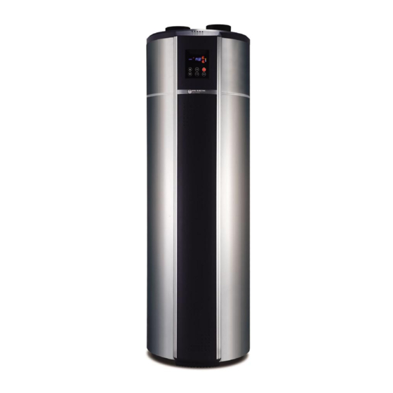
B. Descripción del producto Aspecto de la unidad (exterior): Cubierta superior Entrada/salida del aire Pantalla del panel Cubierta superior Orificio del desbordamiento del Barra de decoración condensado Panel eléctrico Tubería de ventilación Compresor Ventilador de ventilación Evaporador Barra de decoración Chasis principal dcha/izda Panel decorativo... -
Page 5: Instrucciones De Instalación
C. Instrucciones de instalación Nota: 1. Esta unidad de bomba de calor se puede instalar en la galería, pasillo u otro lugar donde sea fácil de instalar y esté estable. La entrada y salida de aire están en el lado superior por lo que la unidad principal no debe colocarse al aire libre. - Page 6 13. La unidad se llena con refrigerante de fábrica, y no es necesario aspirar o rellenar refrigerante. Instalación de los colectores solares (conexión a solar solo disponible en el modelo E301WHF): 1. Al instalar los colectores solares, la solución más óptima es hacia el sur (nota: hacia el norte para el hemisferio sur).
- Page 7 C. Instrucciones de instalación Conexión de la unidad integrada (conexión a solar solo disponible en el modelo E301WHF) 1. Para la conexión de las tuberías de la unidad integrada, consulte (Fig. 5) "Diagrama de instalación de tuberías". En la unidad del sistema, deben instalarse válvulas de tres puertos, válvula de seguridad, filtro, unidad principal y colectores solares.
- Page 8 C. Instrucciones de instalación Diagrama de instalación (conexión a solar solo disponible en el modelo E301WHF): Entrada de aire Salida de aire Tubería de 风 ventilación CLOCK ON/OFF Sensor de temperatura TIMER MODE Válvula de escape Drenaje del desbordamiento de condensado...
-
Page 9: Instrucciones Del Panel De Funcionamiento
D. Instrucciones del panel de funcionamiento 1. Panel - Funcionamiento: PANTALLA Muestra el modo de funcionamiento, estado, temperatura del agua, tiempo etc. ON/OFF Enciende y apaga la unidad Cuando la unidad está encendida, la pantalla muestra "HTG" (Heating-calentamiento), "DEF" (desfrost- descongelación) o "Warm"... - Page 10 D. Instrucciones del panel de funcionamiento 2. Panel - Pantalla: Ajuste temperatura Temperatura alta Alarma Resistencia de apoyo Estado HTG: Heating (calentamiento) DEF: Defrost (descongtelación) WARM: Keep warm (Mantiene caliente) Modo de funcionamiento Ajuste de hora Hora Temporizador ON Temporizador OFF Periodos temporizador Temperatura agua Gradiente de temperatura...
- Page 11 D. Instrucciones del panel de funcionamiento 3. Ajuste de parámetros: Presione el botón "MODE" durante 5 segundos; ingrese el estado de configuración de parámetros, los códigos de parámetros principales son los que se muestra a continuación: Observaciones Nombre del parámetro Tipo Código Rango de ajuste...
- Page 12 D. Instrucciones del panel de funcionamiento 4. Manejo de errores: Código de error Estado de error Razones Manejo del error Sensor de la temperatura del 1. Compruebe la conexión del Alarma del sensor termal sensor de temperatura del agua. agua de circuito abierto o 2.
-
Page 13: Mantenimiento Y Servicio
E. Mantenimiento y servicio Examen antes de la prueba 1. Verifique que el tanque de agua esté lleno de agua y abra el grifo de salida de agua hasta que salga el agua. 2. Verifique que la presión del agua sea normal (0.15Mpa ~ 0.7Mpa). 3. - Page 14 E. Mantenimiento y servicio Desmontaje de la unidad principal Si desea verificar y mantener las partes principales superiores de la unidad y debe desarmar la cubierta de la unidad, siga los pasos a continuación (Fig. 5, 6) para el proceso. CLOCK ON/OFF TIMER...
-
Page 15: Diagrama De Circuito De La Unidad
F. Diagrama de circuito de la unidad El siguiente es un diagrama de circuito de la unidad (para referencia del usuario); La conexión de la unidad debe ser como el diagrama de circuito / cableado de la máquina. SESOR TEMP. AGUA Panel de SENSOR TEMP. -
Page 16: Lista Anexa
G. Lista anexa Especificación Nombre Cantidad Observación ITEM Válvula de seguridad 0.7Pa Válvula 3 puertos Filtro Manual En base a la norma europea del 2012/19 /UE de residuos de aparatos eléctricos y electrónicos (RAEE), los electrodomésticos no pueden ser arrojados en los contenedores municipales habituales;... - Page 17 Requisitos de calidad del agua en el circuito La calidad del agua debe cumplir los estándares de la Directiva Europea 98/83 CE y los criterios indicados en la Norma UNE 112.076. La calidad del agua se debe analizar antes de su uso; para evaluar criterios como el valor de pH, la conductividad, la concentración de iones de cloruro (Cl-), la concentración de iones de sulfuro (S2-), etc.
- Page 18 CONDICIONES DE LA GARANTÍA COMERCIAL Este producto tiene una garantía de reparación de dos años a partir de la fecha de venta, contra todo defecto de funcionamiento proveniente de la fabricación, incluyendo mano de obra y piezas de recambio, y cinco años de garantía en el compresor (solo componente).
- Page 19 Daños en fusibles, lamas, focos, flujostato de caudal, filtros y otros elementos derivados del desgaste normal debido a la operación del equipo. Las averías que tengan su origen o sean consecuencia directa o indirecta de: contacto con líquidos, productos químicos y otras sustancias, así como de condiciones derivadas clima...
- Page 20 CONTENTS A. IMPORTANT REMARKS ------------------------------------------------------------------------------------------------ 1 B. DESCRIPTION OF HEAT PUMP ------------------------------------------------------------------------------------- 2 C. INSTALLATION INSTRUCTION------------------------------------------------------------------------------------ 3-6 D. OPERATION PANEL INSTRUCTION----------------------------------------------------------------------------7-10 E. MAINTENANCE AND SERVICE -------------------------------------------------------------------------------- 11-13 F. UNIT CIRCUIT DIAGRAM--------------------------------------------------------------------------------------------- 14 G. ANNEX LIST ------------------------------------------------------------------------------------------------------------- 15 WARNING: 1. This unit must be installed by the professional persons, dealers or special installation companies authorized.
-
Page 21: Important Remarks
A. Important remarks Thank you for choosing our products. Before installation, it is strongly recommended to read this instruction firstly. This manual includes the information of installation, debugging, running and maintenance of the products. Every unit of products has passed strictly test to ensure safety and high efficiency operation. The manufacturer of this product will not be held responsible if someone is injured or the unit is damaged, as a result of improper installation, debugging, and unnecessary maintenance which is not in line with this manual. -
Page 22: Description Of Heat Pump
B. Description of heat pump Unit constructions (outside): Top Cover Air Inlet / Outlet Screen Panel Upper Cover Condensate Overflow Hole Decoration Bar Electric Board Vent Pipe Compressor Evaporator Ventilation Fan Host Chassis Left/Right Decoration Bar Decoration Panel Chassis Installation Board Hot Water Outlet Magnesium Hole Safety Valve... -
Page 23: Installation Instruction
C. Installation instruction Note: 1. This heat pump unit can be installed at veranda, hallway or other place where is easy to install and stable. The air inlet and outlet are at the top side, main unit should not be placed at an open air. Avoid φ153mm the rain or debris to enter the vents. - Page 24 13. This water heater unit is filled with refrigerant by the factory, and no need to vacuumize or refill refrigerant. Installation of the solar collectors (solar connection only available in the E301WHF model) 1. When installing the solar collectors, the optimized solution is toward due south (note: due north for south hemisphere).
- Page 25 C. Installation instruction Integrated unit connection (solar connection only available in the E301WHF model) 1. For waterway connection of this integrated unit, please refer to the following (Fig.5) “Waterway installation diagram”. On the system unit, there should be installed Three-port valve, Safety valve, Filter, Main unit and solar collectors.
- Page 26 C. Installation instruction Installation diagram (solar connection only available in the E301WHF model): Air Inlet 进风 出风 Air Outlet 风管 Vent Tube CLOCK ON/OFF TIMER MODE Exhaust Valve Temperature Sensor 温度传感器 排气阀 溢流水管 Condensate Overflow drain 热水出 Hot Water Outlet 太阳能集热板1...
-
Page 27: Operation Panel Instruction
D. Operation panel instruction 1. Panel - Operation:... - Page 28 D. Operation panel instruction 2. Panel - Display: 设定水温显示 Set Temperature 水温高温提示 High Temperature 机器报警指示 Alarm 辅电加热指示 Auxiliary Heater 机器状态指示 Status HTG: Heating DEF: Defrost WARM: Keep warm 工作模式指示 Working Mode 调节时钟指示 Time adjustment 当前时间显示 Time 定时开显示 Timer On 定时关显示 Timer Off 定时时段显示...
- Page 29 D. Operation panel instruction 3. Parameter Setting: Press “MODE” button for 5 seconds; enter the Parameter setting status, the main parameter code as below sheet: Type Code Parameter Name Setting Range Factory Setting Unit Remark °C Setting temperature 5-70 °C Difference in Temp.
- Page 30 D. Operation panel instruction 4. Error Handling: ERROR CODE ERROR STATUS REASONS ERROR HANDLING 1. Check the water temp. sensor Water temp. sensor open circuit Thermal sensor alarm connection. or short circuit. 2. Change the water temp. sensor. 1. Check the condenser coil temp. Condenser coil sensor Condenser coil temp.sensor sensor connection.
-
Page 31: Maintenance And Service
E. Maintenance and service Examination before trial run 1. Check the water tank is filled with water, and open the water outlet tap till water flow out. 2. Check the water pressure is normal (0.15Mpa~0.7Mpa). 3. Check the circulation pipes are filled with water or other anti-freezing liquids. 4. - Page 32 E. Maintenance and service Heat Pump main unit disassembly If want to check and maintain the top main parts of the unit, should disassembly the cover of the unit, follow the below steps (Fig.5, 6) to process. CLOCK ON/OFF TIMER MODE (Fig.5) (Fig.6)
-
Page 33: Unit Circuit Diagram
F. Unit circuit diagram The following is a unit circuit diagram (for user’s reference); the unit practical connection should be as the circuit /wiring diagram on the machine. 水箱探头 WATER TEMP. SENSOR 操作面板 盘管探头 OPERATION PANEL COIL TEMP.SENSOR 时钟 开/关 环境探头... -
Page 34: Annex List
G. Annex list ITEM NAME SPECIFICATION QUANTITY REMARK Safety valve 0.7Pa Three-port valve Filter Manual The european directive to 2012/19 /EU on wasted electrical and electronic equipments (WEEE), requires that household electrical appliances must not be disposed of in the normal unsorted municipal waste stream. appliances must be collected separately in order to optimize the recovery and recycling of the materials they contain, and reduce the impact on human health and the environment. - Page 35 Water quality requirements on the circuit Water quality must meet the standards of European Directive 98/83 EC and the criteria set out in UNE 112.076. Water quality should be analysed before use; to evaluate criteria such as concentration, pH value, conductivity, chloride ion concentration (Cl-), sulfide ion concentration (S2-), etc.
- Page 36 COMMERCIAL GUARANTEE CONDITIONS FOR AIR CONDITIONING This product has a two-year repair guarantee from the date of sale, against all manufacturing malfunctions, including repairwork and replacement parts, and a five-year guarantee on the compressor (component only). To justify the purchase date, it will be mandatory to present the end user's invoice or purchase receipt and the installation company data.
- Page 37 15. Damage to fuses, blades, lamps, flow switch, filters and other elements derived from normal wear and tear due to the operation of the equipment. 16. Faults that have their origin or are a direct or indirect consequence of: contact with liquids, chemicals and other substances, as well as conditions derived from the climate or the environment: earthquakes, fires, floods, excessive heat or any other external force , such as insects, rodents and other animals that may have access to...