Table of Contents
Advertisement
Available languages
Available languages
Quick Links
M-THERMAL 2 MONOBLOCK
M-THERMAL 2 MONOBLOCK
ETH080VMA
ETH100VMA
ETH125VMA
ETH160VMA
MANUAL DE
INSTRUCCIONES
INSTRUCTION MANUAL
Escanee para ver este manual en otros idiomas y actualizaciones
Scan for manual in other languages and further updates
Manuel dans d'autres langues et mis à jour
Manual em outras línguas e actualizações
V.1
Advertisement
Chapters
Table of Contents

Related Manuals for EAS Electric ETH080VMA


Summary of Contents for EAS Electric ETH080VMA
- Page 1 M-THERMAL 2 MONOBLOCK M-THERMAL 2 MONOBLOCK ETH080VMA ETH100VMA ETH125VMA ETH160VMA MANUAL DE INSTRUCCIONES INSTRUCTION MANUAL Escanee para ver este manual en otros idiomas y actualizaciones Scan for manual in other languages and further updates Manuel dans d'autres langues et mis à jour...
-
Page 2: Table Of Contents
CONTENIDO PRECAUCIONES DE SEGURIDAD INTRODUCCIÓN GENERAL 2.1 Accesorios proporcionados con la unidad ANTES DE LA INSTALACIÓN INFORMACIÓN IMPORTANTE SOBRE EL REFRIGERANTE LUGAR DE INSTALACIÓN Selección de ubicación en climas fríos Evitar la luz del sol PRECAUCIONES DE INSTALACIÓN Dimensiones Requisitos de instalación Posición del agujero de desagüe Dimensiones de instalación requeridas APLICACIONES TÍPICAS... - Page 3 Puesta en marcha inicial en baja temperatura 10.3 Comprobaciones 10.4 Bomba de circulación 10.5 Ajustes instalación 10.6 COMPROBACIÓN DE FUNCIONAMIENTO Y PRUEBAS FINALES 11.1 Comprobaciones finales 11.2 Comprobación funcionamiento (manual) MANTENIMIENTO Y SERVICIO SOLUCIÓN DE PROBLEMAS 13.1 Instrucciones generales 13.2 Síntomas generales 13.3 Parámetros funcionamiento...
- Page 4 8/10/12/14/16 kW 4/6 kW Diagrama interno: 12~16kW(trifásica) por ejemplo 4/6 kW Sistema control eléctrico Bornero Sistema hidráulico Sistema refrigerante 8/10/12/14/16 kW Retire la chapa hueca después de la instalación Retire el soporte para el transporte 12/14/16 kW NOTA Las imágenes y funciones descritas en este manual contienen los componentes calefactores auxiliares. Las ilustraciones de este manual son sólo como referencia, la imagen del producto real es la que prevalece.
- Page 5 1. ADVERTENCIAS DE SEGURIDAD Las advertencias aquí recogidas se dividen en las siguientes categorías. Son muy importantes, así que asegúrese de seguirlas atentamente. Significado de los símbolos de PELIGRO, ADVERTENCIA, ATENCIÓN y NOTA. INFORMACIÓN • Lea atentamente estas instrucciones antes de la instalación, y conserve el manual para futura referencia. •...
- Page 6 PELIGRO • Antes de tocar los bornes de conexión eléctrica, apague la corriente. • Al retirar los paneles, lleve cuidado de no tocar ningún cable por accidente. • Nunca deje la unidad desatendida durante la instalación o mantenimiento mientras no lleve los paneles protectores. •...
- Page 7 No instale la unidad en los siguientes sitios: - Donde pueda haber contacto con aceite mineral, salpicaduras de aceite o vapores. Esto puede deteriorar las partes de plástico y que se suelten o que haya goteo de agua. - Donde haya gases corrosivos (como gas de ácido sulfúrico): la corrosión de las tuberías de cobre o de las soldaduras puede conllevar una fuga de refrigerante.
-
Page 8: Introducción General
2. INTRODUCCIÓN GENERAL Estas unidades se utilizan tanto para aplicaciones de calefacción y refrigeración como para depósitos de agua caliente sanitaria. Se pueden combinar con unidades fan coil, suelo radiante, radiadores de alta eficiencia de baja temperatura, depósitos de agua caliente sanitaria y kits solares, que se suministran aparte. La unidad viene equipada con un mando por cable. -
Page 9: Antes De La Instalación
3 ACCESORIOS En el modo de refrigeración, el rango de temperatura agua fluye (TW_out) diferentes 3.1 Accesorios incluidos temperaturas exteriores (T4) enumera continuación: con la unidad Piezas de instalación Cantidad Nombre Forma Manual de instrucciones (este libro) Manual funcionamiento Manual datos técnicos Rango de funcionamiento por bomba de calor con posible limitación y protección. -
Page 10: Información Importante Sobre El Refrigerante
ATENCIÓN Para evitar lesiones, no toque la entrada de aire y las aletas de aluminio de la unidad. No sujete la unidad por la rejilla para evitar roturas. La parte superior de la unidad es muy pesada, evite inclinarla durante el transporte para que no se caiga. ≥1000mm El gancho y el baricentro de la unidad deben estar... -
Page 11: Lugar De Instalación
ATENCIÓN Frecuencia de comprobaciones de fuga de refrigerante - Para unidades que contengan gases fluorados de efecto invernadero en cantidades de 5 toneladas de CO equivalente o más, pero de menos de 50 toneladas de CO equivalente: al menos cada 12 meses, o si se instala un sistema de detección de fugas, al menos cada 24 meses. -
Page 12: Selección De Ubicación En Climas Fríos
Si instala la unidad en un soporte, añada placa resistente agua (de unos 100mm, en la parte inferior de la unidad) para evitar que gotee agua. (Véase la imagen de la derecha). A(mm) Unidad 4~6kW ≥300 ≥300 8~16kW 5.1 Selección de ubicación en climas fríos En lugares con fuertes vientos cuya dirección se Consulte el apartado "Manipulación de la unidad"... -
Page 13: Dimensiones
7 ADVERTENCIAS DE INSTALACIÓN 7.1 Dimensiones 8/10/12/14/16 kW (unidad: mm) 4/6 kW (unidad: mm) Modelo 4/6kW 1295 8/10/12/14/16kW 1385 7.2 Requisitos de instalación Compruebe la resistencia y nivel de la base de instalación para que la unidad no cause ruidos ni vibración durante el funcionamiento. -
Page 14: Posición Del Agujero De Desagüe
7.3 Posición del agujero de desagüe Agujero de desagüe Agujero de desagüe 4/6 kW agujero desagüe está cubierto tapón de goma. Si el agujero pequeño no cumple requisitos, se puede usar el grande al mismo tiempo. 8/10/12/14/16 kW NOTA Se debe instalar un cinturón de calefacción eléctrica si no se drena el agua en clima frío aunque esté abierto el desagüe grande. - Page 15 7.4.2 Para instalaciones en múltiples filas (para el tejado, etc.) En caso de instalar varias unidades conectadas lateralmente por fila. ≥500mm ≥500mm 1/2 H Unidad A(mm) B1(mm) B2(mm) C(mm) 4~6kW ≥2500 ≥1000 ≥600 ≥300 8~16kW ≥3000 ≥1500...
-
Page 16: Aplicaciones Típicas
8 APLICACIONES TÍPICAS Los ejemplos de aplicación siguientes tienen sólo fines ilustrativos. 8.1 Aplicación 1 Interior Exterior FHL1 FHL2 FHLn 11.2 Modbus 11.1 11.3 Unidad de montaje Unidad de montaje Código Código Tanque de agua caliente sanitaria Unidad exterior 11.1 TBH: Calentador de refuerzo del tanque de Interfaz de usuario agua caliente sanitaria... - Page 17 Calefacción del espacio La señal de ON/OFF, el modo de funcionamiento y el ajuste de temperatura se configuran en la interfaz de usuario. P_o (6) sigue funcionando mientras la unidad esté encendida para calentar el espacio, SV1(4) se mantiene apagado. Agua caliente sanitaria La señal de ON/OFF y la temperatura objetivo del tanque de agua (T5S) se configuran en la interfaz de usuario.
-
Page 18: Aplicación
8.2 Aplicación 2 TERMOSTATO DE PARED EL control por zonas del espacio en refrigeración o calefacción se deben configurar en la interfaz de usuario. Se puede configurar de tres formas: CONFIGURACIÓN DE MODO/ZONA ÚNICA/DOBLE ZONA. La unidad interior se puede conectar a un termostato de pared de alto voltaje y a uno de bajo voltaje. También se puede conectar a un módulo hidráulico, al cual se pueden conectar otros seis termostatos. - Page 19 8.2.2 Control de configuración de modo Interior Exterior FCU1 FCU2 FCUn FHL1 FHL2 FHLn Código Unidad de montaje Código Unidad de montaje Unidad principal Válvula de desagüe Colector/distribuidor Interfaz de usuario Tanque de equilibrio Válvula de derivación Válvula de descarga automática Placa de transferencia de termostato SV2: válvula de 3 vías Válvula de desagüe...
- Page 20 8.2.3 Control de doble zona Interior Exterior RAD.1 ZONA1 RAD.2 RAD.n ZONA2 23.1 23.2 Modbus FHL1 FHL2 FHLn Código Código Unidad principal Colector/distribuidor Interfaz de usuario Placa de transferencia de termostato Tanque de equilibrio Estación de mezclado Válvula de descarga automática 23.1 SV3: válvula de mezclado Válvula de desagüe...
- Page 21 NOTA 1) La Zona 2 sólo puede funcionar en modo calefacción. Cuando el modo refrigeración se configure en el mando y la zona 1 esté apagada, se cierra "CL" en la zona 2 y el sistema sigue apagado. Durante la instalación, debe comprobar que el cableado de los termostatos de la zona 1 y zona 2 es correcto.
- Page 22 Válvula de purga de aire a utomática Colector/distribuidor (suministro Contactor (suministro sobre el (suministro sobre el terreno sobre el terreno) terreno) Manómetro para el agua El espacio funciona en modo de Válvula de derivación (suministro (suministro sobre el terreno) calefacción o de refrigeración sobre el terreno) Sensor de temperatura del flujo de El espacio solo funciona en...
-
Page 23: Sistema Paralelo
NOTA 1) Puede instalarse un máximo de 6 unidades en cascada. Una de ellas será la unidad maestra y el resto son unidades esclavas. Se distinguen según si están conectadas al mando por cable al encenderse. La unidad con el mando por cable es la maestra, y las que no tengan conexión a un mando por cable son unidades esclavas. - Page 24 9.2 Componentes principales 9.2.1 Módulo hidráulico 4/6 kW con calefactor auxiliar (opcional) 4/6 kW sin calefactor auxiliar 8~16 kW sin calefactor auxiliar 8~16 kW con calefactor auxiliar (opcional) Código Unidad Explicación El aire restante en el circuito de agua se eliminará Válvula de purgado de aire automáticamente.
- Page 25 9.3 Caja de control eléctrico Nota: La imagen es solo para referencia, consulte el producto real. Placa control módulo inverter (PCB A) Placa control del sistema de Placa principal del módulo hidráulico bomba de calor (PCB B) 4/6kW Placa control módulo inverter (PCB A) Placa control del sistema de...
- Page 26 Placa principal del módulo hidráulico Placa control módulo inverter (PCB A) Placa control del sistema de bomba de calor (PCB B) 12/14/16kW(Monofásica) Placa principal del módulo hidráulico Placa control módulo inverter (PCB A) Placa control del sistema de bomba de calor (PCB B) Placa filtro (PCB C) (en la parte trasera de la PCB B, sólo para unidades trifásicas)
- Page 27 CN24 CN21 CN28 CN16 CN32 CN13 CN15 CN29 CN18 CN25 CN42 CN40 DIS1 CN41 CN31 CN22 CN35 CN36 CN17 25 26 27 14 15 CN11 CN30 Terminal Terminal Orden Código Unidad de montaje Orden Código Unidad de montaje M1 M2 POWER Terminal alimentación Terminal para switch remoto...
- Page 28 9.3.2 Monofásica para unidades 4-16kW 1) PCB A, 4-10kW,módulo inverter Notas: para 4-6kw, dos condensadores CN20 Código Unidad de montaje Unidad de montaje Código Terminal conexión compresor U Reservado(CN302) Terminal conexión compresor V Terminal comunicación con PCB B(CN32) Terminal entrada N para puente rectificador(CN502) Terminal conexión compresor W Terminal de salida para +12V/9V(CN20) Terminal entrada L para puente rectificador(CN501)
- Page 29 2) PCB B, Placa de control principal para sistema de bomba de calor CN10 CN27 CN11 CN22 CN24 CN17 CN26 CN28 CN13 CN55 CN18 CN14 CN29 CN7 CN5 CN6 CN16 CN19 CN21 CN33 CN2 CN30 CN36 CN37 CN38 CN20 26 25 24 Código Unidad de montaje Código...
- Page 30 9.3.4 12~16kW unidades trifásicas 1) PCB A módulo inverter CN16 CN22 CN15 CN23 CN17 CN18 CN20 CN19 Código Unidad de montaje Unidad de montaje Código Terminal entrada P_in para módulo IPM (CN1) Terminal salida para +15V(CN20) Terminal W de conexión del compresor (CN19) Terminal de comunicación con PCB B (CN8) Terminal V de conexión del compresor (CN18) Placa PED (CN22)
- Page 31 2) PCB B, Placa de control principal para sistema de bomba de calor CN41 CN26 CN24 CN36 CN21 CN18 CN31 CN29 CN10 CN35 CN11 CN28 CN20 CN37 CN27 V i n CN22 CN30 CN38 CN53 CN109 Código Unidad de montaje Unidad de montaje Código Terminal para sonda temperatura Tp(CN8)
- Page 32 3) PCB C, placa de filtro CN204 CN205 CN206 CN30 CN213 CN214 CN202 CN211 CN203 CN200 CN201 CN212 PCB C Trifásica 12/14/16kW Código Unidad de montaje Código Unidad de montaje Filtro de energía L3(L3’) Alimentación L2 (CN201) Alimentación L3 (CN200) Filtro de energía L2(L2’) Alimentación N (CN203) Filtro de energía L1(L1’)
- Page 33 9.3.5 Componentes de control calefactor auxiliar (Opcional) Monofásica 4/6kW con calefactor auxiliar (Monofásica 3kW) Monofásica 8-16kW con calefactor auxiliar Monofásica 8-16kW con calefactor auxiliar (Monofásica 3kW) (Trifásica 9kW) Trifásica 12-16kW con calefactor Trifásica 12-16kW con calefactor auxiliar(Monofásica 3kW) auxiliar(Trifásica 9kW) Código Unidad Código...
- Page 34 9.4 Tuberías de agua Se deben tener en cuenta todas las longitudes y distancia de las tuberías. Requisitos Válvula La longitud máxima permitida del cable del termistor es de 20 m. Esta es la distancia máxima permitida entre el tanque de agua caliente sanitaria y la unidad (solo para instalaciones con tanque de agua caliente sanitaria).
- Page 35 Antes de continuar con la instalación de la unidad, verifique lo siguiente: • La presión máxima del agua es ≤ 3 bar. • La temperatura máxima del agua es ≤ 70°C según la configuración del dispositivo de seguridad. • Utilice siempre materiales que sean compatibles con el agua utilizada en el sistema y con los materiales utilizados en la unidad.
- Page 36 9.4.3 Conexión del circuito de agua 9.4.4 Protección anticongelación del circuito de agua Las conexiones de agua deben realizarse correctamente Todas las partes hidrónicas internas están aisladas para reducir la pérdida de calor. También se debe agregar aislamiento a la de acuerdo con las etiquetas de la unidad exterior, con respecto a la entrada y salida de agua.
-
Page 37: Llenado
ATENCIÓN Si la unidad no se va a usar durante mucho tiempo, asegúrese de que tenga corriente en todo momento. Si desea cortar la corriente, el agua de las tuberías del sistema debe drenarse para evitar que la unidad y el sistema de tuberías se dañen por congelación. - Page 38 9.6 Aislamiento del circuito de agua El circuito de agua completo, incluidas todas las tuberías de agua, deben estar aisladas para evitar la condensación durante la operación de refrigeración y la reducción de la capacidad de calefacción y refrigeración, así como para evitar la congelación de las tuberías de agua exteriores durante el invierno.
- Page 39 1OFF 2OFF P _o AHS1 AHS2 DFT2 DFT1 IBH1 3OFF CN11 CN30 25 T Código Unidad de montaje Código Unidad de montaje Unidad exterior P_d: bomba de ACS(suministro sobre el terreno) ) Kit de energía solar(suministro sobre el terreno) SV2: válvula de 3 vías(suministro sobre el terreno) ) SV1: válvula de 3 vías para depósito de agua Interfaz de usuario caliente sanitaria(suministro sobre el terreno)
- Page 40 NOTA Utilice H07RN-F para el cable de alimentación, todos los cables están conectados a alto voltaje, excepto el cable del termistor y el cable para la interfaz de usuario. • El equipo debe estar conectado a tierra. • Toda carga externa de alto voltaje, si es de metal o un puerto con conexión a tierra, debe estar conectada a tierra. •...
- Page 41 Instrucciones de cableado La mayor parte del cableado de campo de la unidad debe realizarse en el bornero del interior de la caja de interruptores. Para acceder al bornero, retire el panel de servicio de la caja de interruptores (puerta 2). ADVERTENCIA Desconecte toda la energía, incluida la fuente de alimentación de la unidad y el calentador auxiliar y la fuente de alimentación del tanque de agua caliente sanitaria (si corresponde) antes de retirar el panel de servicio de la caja de...
-
Page 42: Cableado
Tabla 9-1 Voltaje nominal Área de sección transversal nominal (mm)2 del aparato:(A) Cable flexible Cableado fijo 0.5 and 0.75 and 2.5 ≤ 0.75 and 1 and 2.5 > ≤ and 1.5 and 2.5 > ≤ 10 and 1.5 and 2.5 1.5 and 4 >... - Page 43 NOTA MCA: Ampacidad máxima del circuito (A) TOCA: Amperaje total de sobrecorriente (A) MFA: Amperaje máximo de fusible (A) MSC: Ampacidad requerida para el arranque. (A) RLA: En condiciones de prueba de refrigeración o calefacción nominal, los amperios de entrada del compresor donde puede funcionar MAX. Hz - Amperaje de carga nominal (A);...
- Page 44 Selecc. unidad maestra Utilice cable apantallado y conectado a tierra. H1 H2 H1 H2 H1 H2 ..Maestra Esclava 1 Esclava 2 Esclava X Sólo necesita la resistencia adicional en P y Q la última unidad interior. Fusible Fusible Fusible Fusible Resistencia adicional On/Off...
- Page 45 Cuando conecte al terminal de la fuente de alimentación, utilice el terminal de tipo ojal con la carcasa de aislamiento (consulte la Figura 9.1). Utilice un cable de alimentación que cumpla con las especificaciones y conéctelo firmemente. Para evitar que el cable se salga por fuerza externa, asegúrese de que esté...
- Page 46 9.7.6 Conexión de otros componentes Unidad 4-16kW P_c P_o P_s P_d AHS1 1OFF AHS2 2OFF IBH1 N 3ON DFT2 DFT1 3OFF CN11 CN30 Código Código Conecta con Conecta con Señal entrada ① energía solar Mando por cable ① Entrada termostato de pared ②...
- Page 47 25 26 1 2 3 4 5 29 30 31 32 6 7 8 9 10 CN11 CN30 25 26 27 28 1 2 3 4 5 29 30 31 32 6 7 8 9 10 CN11 CN30 Alimentación 7 5 3 1 8 6 4 Contactor (Calefactor refuerzo)
- Page 48 5) Para bomba de tubería Pumpc y ACS: 25 26 27 28 1 2 3 4 5 29 30 31 32 6 7 8 9 10 CN11 CN30 25 26 27 28 1 2 3 4 5 Alimentación 29 30 31 32 6 7 8 9 10 7 5 3 1 CN11...
- Page 49 Método C (Control doble zona) El módulo hidráulico está conectado con dos termostatos de ambiente, mientras que la interfaz de usuario FOR SERVICEMAN configura el TERMOSTATO DE HABITACIÓN en DOBLE ZONA: C.1 Cuando el voltaje de detección de la unidad es de 230 VCA entre H y L1, la zona 1 se enciende.
- Page 50 8) Para control del calefactor auxiliar C.2 Cuando el voltaje de detección de la unidad es de 12VCC entre CL y COM, la zona 2 se enciende de acuerdo con la curva de temperatura climática. Cuando la unidad detecta un voltaje de 0 V entre CL y COM, la zona 2 se apaga.
- Page 51 Voltaje 220-240VAC 11) Red inteligente: Corriente máxima de funcionamiento (A) La unidad tiene función de red inteligente, hay dos puertos 0.75 Sección cable (mm en la placa para conectar la señal de red inteligente y la señal EVU de la siguiente manera: Type 1 Tipo de señal del puerto de control CN24...
-
Page 52: Puesta En Marcha Y Configuración
10 PUESTA EN MARCHA Y CONFIGURACIÓN El instalador debe configurar la unidad para que coincida con el entorno de instalación (clima exterior, opciones instaladas, etc.) y la experiencia del usuario. ATENCIÓN Es importante que el instalador lea toda la información de este capítulo y que el sistema esté configurado según las instrucciones. - Page 53 Curvas de temperatura para modo refrigeración - 10≤ T4<15 15≤ T4<22 22≤ T4<30 30≤ T4 1- T1S 2- T1S 3- T1S 4- T1S 5- T1S 6- T1S 7- T1S 8- T1S - 10≤ T4<15 15≤ T4<22 22≤ T4<30 30≤ T4 1- T1S 2- T1S 3- T1S...
-
Page 54: Comprobaciones
Valor Valor Valor fábrica fábrica fábrica Unidad maestra: Inicio PumpO Inicio PumpO Conserva borra las 0/0=3kW IBH (Control direcciones de tras 6 horas tras 6 horas de una etapa) todas las unidades será inválido será válido dirección 0/1=6kW IBH (Control esclavas actual de dos etapas) -
Page 55: Bomba De Circulación
10.5 Bomba de circulación Las relaciones entre la altura y el caudal de agua nominal, el retorno PMW y el caudal de agua nominal se muestran en el gráfico siguiente. 4- 10kW (La bomba mantiene la salida máxima) Tasa de caudal(m /h)... - Page 56 ATENCIÓN Si el sistema se pone en marcha con las válvulas en posición incorrecta o cerradas, la bomba de circulación se dañará. PELIGRO Si es necesario verificar el estado de funcionamiento de la bomba cuando la unidad está encendida, no toque los componentes internos de la caja de control electrónico para evitar descargas eléctricas.
- Page 57 Menú FOR SERVICEMAN 10.6.1 Ajuste modo ACS FOR SERVICEMAN permite a los instaladores acceder a la configuración del sistema y establecer los ACS (DHW) = Agua caliente sanitaria parámetros del sistema. Vaya a MENU> SERVICEMAN> 1.DHW MODE SETTING. Pulse OK para acceder a las Ajuste de la composición del equipo.
- Page 58 2 COOL MODE SETTING 10.6.5 AJUSTE TIPO TEMPERATURA 2.1 COOL MODE 2.2 t_T4_FRESH_C 2.0HRS El TIPO DE AJUSTE DE TEMPERATURA se utiliza para 2.3 T4CMAX 43°C seleccionar si se utiliza la temperatura del flujo de agua o la 2.4 T4CMIN 20°C temperatura ambiente para controlar el ENCENDIDO/ 2.5 dT1SC...
- Page 59 10.6.7 Otras FUENTES DE CALOR En este caso, el valor de ajuste de la zona 1 es T1S, el valor de ajuste de la zona 2 es T1S2. El menú OTHER HEATING SOURCE se usa para configurar los parámetros del calentador auxiliar, de las Si configura DOUBLE ZONE y ROOM TEMP.
- Page 60 9 SERVICE CALL Si se selecciona YES, se mostrarán las siguientes páginas: PHONE NO. 33512345678 MOBILE NO. 8613929145152 11 TEST RUN 11.1 POINT CHECK 11.2 AIR PURGE 11.3 CIRCULATION PUMP RUNNING CONFIRM ADJUST 11.4 COOL MODE RUNNING 11.5 HEAT MODE RUNNING El número que se muestra en la interfaz de usuario es el número de teléfono de su servicio técnico o distribuidor local.
- Page 61 Cuando esté en modo de purga de aire, SV1 se abrirá, Durante la ejecución de la prueba del MODO CALOR, la SV2 se cerrará. 60 segundos después, la bomba de la temperatura objetivo predeterminada del agua de salida unidad (PUMPI) funcionará durante 10 minutos durante es 35°C.
- Page 62 MENU> FOR SERVICEMAN> 12.SPECIAL Durante el precalentamiento del suelo, ningún botón FUNCTION. excepto OK es válido. Si desea apagar el precalentamiento del suelo, presione OK y se mostrará la Si queda una gran cantidad de agua en el suelo, el suelo siguiente página: puede deformarse o incluso romperse durante la operación de calefacción por suelo radiante.
- Page 63 Seleccionado OPERATE FLOOR DRYING con el cursor,use MENU> FOR SERVICEMAN>13.AUTO RESTART para desplazarse a YES y pulse OK. Se muestra la siguiente página: 13 AUTO RESTART 12.2 FLOOR DRYING UP 13.1 COOL/HEAT MODE DO YOU WANT TO TURN OFF THE 13.2 DHW MODE FLOOR DRYING UP FUNCTION? ADJUST...
- Page 64 10.6.16 Parámetros ajuste Los parámetros relacionados con este capítulo se muestran en la siguiente tabla. Intervalo Número Código Estado Predet. Mínimo Máximo Unidad ajuste DHW MODE Activar o desactivar el modo ACS: 0 = NO, 1 = SÍ DISINFECT Activar o desactivar el modo de desinfección: 0 = NO, 1 = SÍ DHW PRIORITY Activar o desactivar el modo de prioridad de ACS: 0 = NO, 1 = SÍ...
- Page 65 HEAT MODE Activar o desactivar el modo de calefacción Tiempo de actualización de las curvas relacionadas t_T4_FRESH_H hours con el clima para el modo de calefacción. Temperatura ambiente máxima de funcionamiento para el T4HMAX ℃ modo de calefacción. Temperatura ambiente mínima de funcionamiento para T4HMIN ℃...
- Page 66 12.4 t_DRYUP Día del calentamiento durante secado del suelo. Días de continuación en alta temperatura durante 12.5 t_HIGHPEAK el secado del suelo Día en que baja la temperatura durante el secado 12.6 t_DRYD del suelo La temperatura máxima objetivo del flujo de agua 12.7 T_DRYPEAK °C...
-
Page 67: Comprobaciones Finales
11 PRUEBA DE FUNCIONAMIENTO Las siguientes verificaciones deben ser realizadas al menos una vez al año por un técnico cualificado. Y COMPROBACIONES FINALES • Presión del agua Verifique la presión del agua, si está por debajo de 1 El instalador está obligado a verificar el correcto bar, llene el sistema con agua. -
Page 68: Solución De Problemas
13 SOLUCIÓN DE PROBLEMAS Esta sección proporciona información útil para diagnosticar y corregir ciertos problemas que pueden ocurrir en la unidad. Esta solución de problemas y las acciones correctivas relacionadas solo pueden ser realizadas por su técnico local. 13.1 Instrucciones generales Antes de iniciar el procedimiento de solución de problemas, realice una inspección visual minuciosa de la unidad y busque defectos obvios como conexiones sueltas o cableado defectuoso. - Page 69 Síntoma 3: la bomba hace ruido (cavitación) CAUSAS POSIBLES ACCIÓN CORRECTIVA Hay aire en el sistema. Purgue el sistema. • Verifique la presión del agua. La presión del agua en La presión del agua debe ser> 1 bar (el agua está fría). la entrada de la bomba •...
- Page 70 Síntoma 8: el modo ACS no puede cambiar al modo Heat inmediatamente CAUSAS POSIBLES ACCIÓN CORRECTIVA • Establezca "t_DHWHP_MAX" en el valor mínimo, el valor sugerido El intercambiador de es 60min. calor para calefacción de • Si la bomba de circulación fuera de la unidad no está controlada por espacios no es lo la unidad, intente conectarla a la unidad.
- Page 71 OPERATION PARAMETER OPERATION PARAMETER OPERATION PARAMETER FAN SPEED 600R/MIN TW_O PLATE W-OUTLET TEMP. 35°C T3 OUTDOOR EXCHARGE TEMP. 5°C IDU TARGET FREQUENCY 46Hz TW_I PLATE W-INLET TEMP. 30°C T4 OUTDOOR AIR TEMP. 5°C FREQUENCY LIMITED TYPE T2 PLATE F-OUT TEMP. 35°C TF MODULE TEMP.
-
Page 72: Códigos De Error
13.4 Códigos de error Cuando se activa el sistema de seguridad, se muestra un código de error en la interfaz de usuario. En la tabla inferior se describe una lista de todos los errores y de sus posibles soluciones. Reinicie el sistema de seguridad apagando la unidad y volviéndola a encender. En caso de que no pueda solucionar el error mostrado, contacte al servicio técnico oficial o a su distribuidor. - Page 73 CAUSA DEL ERROR Y ERROR O CÓDIGO PROTECCIÓN POSIBLE SOLUCIÓN ERROR 1.Compruebe la resistencia del sensor. 2. El conector del sensor Tsolar está aflojado, vuelva a conectarlo. Fallo sonda temperatura 3. El conector del sensor Tsolar está mojado o hay agua Solar (Tsolar) adentro, retire el agua, seque el conector, agregue adhesivo impermeable.
- Page 74 CAUSA DEL ERROR Y ERROR O CÓDIGO POSIBLE SOLUCIÓN PROTECCIÓN ERROR 1.Los cables de señal de las unidades esclavas y la unidad maestra no están conectados de manera efectiva. Después de verificar que todos los cables de señal están bien conectados y de asegurarse de que no haya electricidad fuerte o interferencia magnética fuerte, encienda nuevamente;...
- Page 75 CÓDIGO ERROR O CAUSA DEL ERROR Y PROTECCIÓN POSIBLE SOLUCIÓN ERROR Pérdida de fase o cable de 1. Compruebe los cables de alimentación, evite la pérdida de neutro y fase conectados al fase. revés (sólo para unidades 2. Compruebe que la secuencia de cable de fase y neutro está conectada correctamente.
- Page 76 CÓDIGO ERROR O CAUSA DEL ERROR Y ERROR PROTECCIÓN POSIBLE SOLUCIÓN 1. Si hay viento fuerte, puede impactar frontalmente contra el ventilador y hacerlo girar en la dirección contraria. Cambie la dirección de la instalación o cúbrala para evitar que el viento Fallo del motor ventilador DC afecte al ventilador.
- Page 77 CÓDIGO ERROR O CAUSA DEL FALLO Y ERROR PROTECCIÓN POSIBLE SOLUCIÓN Modo calor y modo ACS: 1. Si el caudal de agua es bajo y la temperatura del agua es alta, compruebe si hay aire en el sistema de agua y púrguelo. 2.
- Page 78 1. Voltaje de alimentación de la unidad demasiado bajo, aumente el voltaje hasta el rango requerido. 2. El espacio entre las unidades es demasiado estrecho para el intercambio de calor. Aumente el espacio entre unidades. 3. El intercambiador de calor está sucio o bloqueado. Límpielo Protección por y retire la obstrucción.
- Page 79 CÓDIGO ERROR O CAUSA DEL FALLO Y ERROR PROTECCIÓN POSIBLE SOLUCIÓN Protección del módulo Protección por bajo voltaje generatriz DC Protección por alta presión del sistema de la bomba de calor Protección por alto voltaje generatriz DC Protección por alta presión del sistema de la bomba de calor 1.
-
Page 80: Especificaciones Técnicas
14 ESPECIFICACIONES TÉCNICAS 14.1 General Monofásica Monofásica Monofásica Trifásica 4/6 kW 8/10 kW 12/14/16 kW 12/14/16 kW Capacidad nominal Consulte el manual técnico Dimensiones (An×Al×Fo)[mm] 718×1295×429mm 865×1385×526mm 865×1385×526mm 865×1385×526mm Dimensiones embalaje 885×1375×475mm 1035×1465×560mm 1035×1465×560mm 1035×1465×560mm (An×Al×Fo)[mm] Peso (sin calefactor auxiliar) Peso neto 86kg 105kg... -
Page 81: Información Mantenimiento
15. INFORMACIÓN DE MANTENIMIENTO 1) Comprobaciones del área Antes de comenzar cualquier trabajo en sistemas que contengan refrigerantes inflamables, debe hacer comprobaciones de seguridad para minimizar el riesgo de incendio. Para hacer cualquier reparación en el sistema de refrigerante, se deben cumplir las siguientes precauciones antes de hacer cualquier trabajo en el sistema. - Page 82 b) Se debe prestar especial atención a las indicaciones siguientes para asegurar que la carcasa no se dañe al manipular los componentes eléctricos de forma que la protección pueda verse alterada. Esto incluye el daño a los cables, conexiones excesivas, terminales no conformes con las especificaciones originales, sellos dañados, montaje incorrecto de entradas de cable, etc.
- Page 83 • Los cilindros deben colocarse en vertical. • Compruebe que el sistema de refrigeración tiene toma de tierra antes de cargar el sistema de refrigerante. • Etiquete el sistema cuando la carga esté completa si no lo ha hecho ya. •...
- Page 84 ANEXO A: Circuito de refrigerante Refrigeración Calefacción Descripción Descripción Núm. Núm. Compresor Sonda temperatura entrada refrigerante (líquido) Válvula de 4 vías Sonda temperatura entrada refrigerante (gas) Separador gas-líquido Sonda temperatura salida agua Intercambiador de calor Sonda temperatura entrada agua Válvula de expansión electrónica Válvula de purgado de aire Válvula electromagnética unidireccional Vaso de expansión...
- Page 85 ANEXO K: Para instalar la cinta calefactora eléctrica en la salida de drenaje (el usuario) Conecte la cinta de revestimiento de alambre en la salida de drenaje a la junta de alambre XT3. A la cinta calefactora de la salida de drenaje. 4/6kW 8/10kW A la cinta calefactora de...
- Page 86 ANEXO K: A la cinta 12/14/16kW(Monofásica) calefactora de la salida de drenaje. 12/14/16kW(Trifásica) A la cinta calefactora de la salida de drenaje. NOTA: La imagen es solo de referencia, consulte el producto real. La potencia de la cinta calefactora electrónica no debe exceder los 40 W / 200 mA, voltaje de suministro 230 V CA.
- Page 87 Requisitos de calidad del agua en el circuito La calidad del agua debe cumplir los estándares de la Directiva Europea 98/83 CE y los criterios indicados en la Norma UNE 112.076. La calidad del agua se debe analizar antes de su uso; para evaluar criterios como el valor de pH, la conductividad, la concentración de iones de cloruro (Cl-), la concentración de iones de sulfuro (S2-), etc.
-
Page 88: Garantía
CONDICIONES DE LA GARANTÍA EAS ELECTRIC ofrece una garantía de reparación contra todo defecto de funcionamiento proveniente de la fabricación, incluyendo mano de obra y piezas de recambio, en los plazos y términos indicados a continuación: 3 años: Gama Doméstica, Gama Comercial, VRV de uso doméstico, M-Thermal Monoblock y Biblock, Fan Coils de uso doméstico, Acumuladores aerotérmicos de ACS, Bombas de Piscina, Minichillers de uso... - Page 89 Con base en la directiva europea 2012/19/UE de residuos de aparatos eléctricos y electrónicos (RAEE), los electrodomésticos no pueden ser arrojados en los contenedores municipales habituales; tienen que ser recogidos selectivamente para optimizar la recuperación y reciclado de los componentes y materiales que los constituyan y reducir el impacto en la salud humana y el medio ambiente.
- Page 90 English CONTENTS SAFETY PRECAUTIONS GENERAL INTRODUCTION ACCESSORIES Accessories supplied with the unit BEFORE INSTALLATION IMPORTANT INFORMATION FOR THE REFRIGERANT INSTALLATION SITE Selecting a location in cold climates Selecting a location in hot climates INSTALLATION PRECAUTIONS Dimensions Installation requirements Drain hole position Servicing space requirements TYPICAL APPLICATIONS Application 1...
- Page 91 Initial start-up at low outdoor ambient temperature 10.3 Pre-operation checks 10.4 The circulation pump 10.5 Field settings 10.6 TEST RUN AND FINAL CHECKS 11.1 Final checks 11.2 Test run operation (manually) MAINTENANCE AND SERVICE TROUBLE SHOOTING 13.1 General guidelines 13.2 General symptoms 13.3 Operation parameter...
- Page 92 4/6 kW 8/10/12/14/16 kW Internal layout:12~16kW(3-phase) for example 4/6 kW Electric Control System Terminal Block Hydraulic System Refrigerant System 8/10/12/14/16 kW Please remove the hollow plate after installation. Remove the transportation support 12/14/16 kW NOTE The picture and function described in this manual contain the backup heater components. Pictures in this manual are for reference only, please refer to the actual product.
-
Page 93: Safety Precautions
1 SAFETY PRECAUTIONS The precautions listed here are divided into the following types.They are quite important, so be sure to follow them carefully. Meanings of DANGER, WARNING, CAUTION and NOTE symbols. INFORMATION Read these instructions carefully before installation. Keep this manual in a handy for future peference. Improper installation of equipment or accessories may result in electric shock, short-circuit, leakage, fire or other damage to the equipment. - Page 94 DANGER Before touching electric terminal parts, turn off power switch. When service panels are removed, live parts can be easily touched by accident. Never leave the unit unattended during installation or servicing when the service panel is removed. Do not touch water pipes during and immediately after operation as the pipes may be hot and could burn your hands.
- Page 95 Do not install the unit in the following places: - Where there is mist of mineral oil, oil spray or vapors. Plastic parts may deteriorate, and cause them to come loose or water to leak. - Where corrosive gases (such as sulphurous acid gas) are produced. Where corrosion of copper pipes or soldered parts may cause refrigerant to leak.
-
Page 96: General Introduction
2 GENERAL INTRODUCTION These units are used for both heating and cooling applications and domestic hot water tanks.They can be combined with fan coil units, floor heating applications, low temperature high efficiency radiators, domestic hot water tanks and solar kits, which are all field supplied. -
Page 97: Accessories
In cooling mode, the water temperature flowing 3 ACCESSORIES (TW_out) range in different outdoor temperature(T4) is listed below: 3.1 Accessories supplied with the unit Installation Fittings Quantity Name Shape Installation and owner’s manual(this book) Operation manual Technical data manual Operation range by heat pump with possible limitation and protection. Y-shape filter In heating mode, the water flowing temperature (TW_out) range in different outdoor temperature (T4) is... -
Page 98: Important Information For The Refrigerant
CAUTION To avoid injury, do not touch the air inlet or aluminum fins of the unit. Do not use the grips in the fan grills to avoid damage. The unit is top heavy! Prevent the unit from falling due to improper inclination during handling. ≥1000mm The hook and barycenter of the unit should be on a line... -
Page 99: Installation Site
CAUTION Frequency of Refrigerant Leakage Checks - For unit that contains fluorinated greenhouse gases in quantities of 5 tonnes of CO equivalent or more,but of less than 50 tonnes of CO equivalent,at least every 12 months, or where a leakage detection system is installed, at least every 24 months. -
Page 100: Selecting A Location In Cold Climates
If you install the unit on a building frame, please install a waterproof tray (field supply) (about 100mm, on the underside of the unit) in order to avoid drain water dripping. (See the picture in the right). A(mm) Unit 4~6kW ≥300 ≥300 8~16kW... -
Page 101: Installation Precautions
7 INSTALLATION PRECAUTIONS 7.1 Dimensions 8/10/12/14/16 kW (unit: mm) 4/6 kW (unit: mm) Model 4/6kW 1295 8/10/12/14/16kW 1385 7.2 Installation requirements Check the strength and level of the installation ground so that the unit may not cause any vibrations or noise during its operation. -
Page 102: Drain Hole Position
7.3 Drain hole position Drain hole Drain hole 4/6 kW This drain hole is covered by rubber plug. If the small drain hole can not meet the drainage requirements, the big drain hole can be used at the same time. 8/10/12/14/16 kW NOTE It's necessary to install an electrical heating belt if water can't drain out in cold weather even the big drain hole has... - Page 103 7.4.2 In case of multiple-row installation (for roof top use, etc.) In case of installing multiple units in lateral connection per row. A(mm) B1(mm) B2(mm) C(mm) Unit ≥2500 ≥1000 4~6kW ≥300 ≥600 ≥3000 ≥1500 8~16kW...
-
Page 104: Typical Applications
8 TYPICAL APPLICATIONS The application examples given below are for illustration only. 8.1 Application 1 Indoor Outdoor FHL1 FHL2 FHLn 11.2 Modbus 11.1 11.3 Code Assembly unit Code Assembly unit Main unit Domestic hot water tank (Field supply) User interface TBH: Domestic hot water tank booster 11.1 heater (Field supply) - Page 105 Space heating The ON/OFF signal and operation mode and temperature setting are set on the user interface. P_o keeps running as long as the unit is ON for space heating, SV1 keeps OFF. Domestic water heating The ON/OFF signal and target tank water temperature (T5S) are set on the user interface. P_o stops running as long as the unit is ON for domestic water heating, SV1 keeps ON.
-
Page 106: Application
8.2 Application 2 ROOM THERMOSTAT Control for Space heating or cooling need to be set on the user interface. It can be set in three ways: MODE SET/ONE ZONE/DOUBLE ZONE. The molobloc can be connected to a high voltage room thermostat and a low voltage room thermostat. - Page 107 8.2.2 Mode set control Indoor Outdoor FCU1 FCU2 FCUn FHL1 FHL2 FHLn Coding Assembly unit Coding Assembly unit Main unit Drainage valve (Field supply) Collector/distributor User interface Balance tank (Field supply ) Bypass valve (Field supply) Automatic air purge valve Thermostat transfer board (Field supply) SV2: 3 - way valve (Field supply)...
- Page 108 8.2.3 Double zone control Indoor Outdoor RAD.1 ZONE1 RAD.2 RAD.n ZONE2 23.1 23.2 Modbus FHL1 FHL2 FHLn Coding Assembly unit Coding Assembly unit Main unit Collector/distributor (Field supply) User interface Thermostat transfer board (ptional) Balance tank (Field supply) Mixing station (Field supply) Automatic bleed valve 23.1 SV3: Mixing valve (Field supply)
- Page 109 NOTE 2) Drainage valve must beinstalled at the lowest position of the piping system. 8.3 Cascade system ( ) Automatic air purge valve...
- Page 110 r manometer Automatic air purge valve...
-
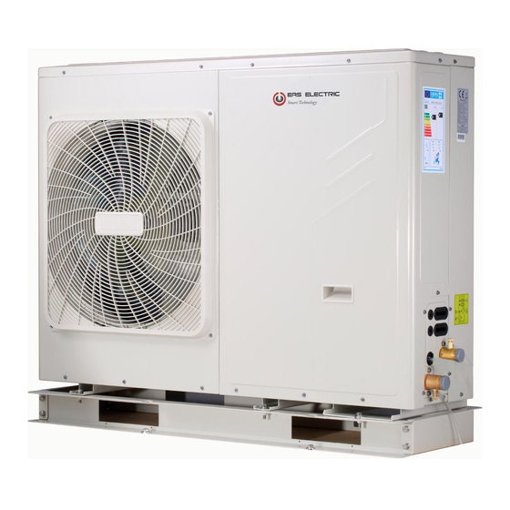
Page 111: Overview Of The Unit
9 OVERVIEW OF THE UNIT 9.1 Disassembling the unit Door 1 To access to the compressor and Door 1 To access to the compressor and electrical parts. electrical parts and hydraulic compartment Door 2 To access to the hydraulic compartment and electrical parts. 4/6kW 8/10/12/14/16kW WARNING... -
Page 112: Main Components
9.2 Main components 9.2.1 Hydraulic module 4/6 kW with backup heater(optional) 4/6 kW without backup heater 8~16 kW without backup heater 8~16 kW with backup heater(optional) Coding Assembly unit Explaination Remaining air in the water circuit will be automatically removes Air purge valve air from the water circuit. -
Page 113: Electronic Control Box
9.3 Electronic control box Note:The picture is for reference only, please refer to the actual product. Inverter module control board(PCB A) Main control board Main control board of hydraulic module of heat pump sysem(PCB B) 4/6kW Inverter module control board (PCB A) Main control board Main control board of hydraulic module... - Page 114 Main control board of hydraulic module Inverter module control board(PCB A) Main control board of heat pump sysem(PCB B) 12/14/16kW(1-phase) Main control board of hydraulic module Inverter module control board(PCB A) Main control board of heat pump sysem(PCB B) Filter board(PCB C)(at back of the PCB B,only for 3 phase unit) 12/14/16kW(3-phase) 9.3.1 Main control board of hydraulic module...
- Page 115 CN24 CN21 CN28 CN16 CN32 CN13 CN15 CN29 CN18 CN25 CN42 CN40 DIS1 CN41 CN31 CN22 CN35 CN36 CN17 25 26 27 14 15 CN11 CN30 Order Port Code Assembly unit Order Port Code Assembly unit M1 M2 POWER Port for power supply Port for remote switch CN21 CN36...
- Page 116 9.3.2 1-phase for 4-16kW units 1) PCB A, 4-10kW,Inverter module Remarks: for 4-6kw, two capacitors CN20 Coding Assembly unit Assembly unit Coding Compressor connection port U Reserved(CN302) Compressor connection port V Port for communication with PCB B(CN32) Input port N for rectifier bridge(CN502) Compressor connection port W Output port for +12V/9V(CN20) Input port L for rectifier bridge(CN501)
- Page 117 2) PCB B, Main control board of heat pump system CN10 CN27 CN11 CN22 CN24 CN17 CN26 CN28 CN13 CN55 CN18 CN14 CN29 CN7 CN5 CN6 CN16 CN19 CN21 CN33 CN2 CN30 CN36 CN37 CN38 CN20 26 25 24 Coding Assembly unit Coding Assembly unit...
- Page 118 9.3.4 3-phase for 12/14/16 kW units 1) PCB A Inverter module CN16 CN22 CN15 CN23 CN17 CN18 CN20 CN19 Coding Assembly unit Assembly unit Coding Input port P_in for IPM module (CN1) Output port for +15V(CN20) Compressor connection port W (CN19) Port for communication with PCB B (CN8) PED board(CN22) Compressor connection port V (CN18)
- Page 119 2) PCB B, Main control board of heat pump system CN41 CN26 CN24 CN36 CN21 CN18 CN31 CN29 CN10 CN35 CN11 CN28 CN20 CN37 CN27 V i n CN22 CN30 CN38 CN53 CN109 Coding Assembly unit Coding Assembly unit Port for temp.sensor Tp(CN8) Port for ground wire(CN38) Port for outdoor ambient temp.
- Page 120 3) PCB C, filter board CN204 CN205 CN206 CN30 CN213 CN214 CN202 CN211 CN203 CN200 CN201 CN212 PCB C 3-phase 12/14/16kW Coding Assembly unit Coding Assembly unit Power supply L2(CN201) Power filtering L3(L3’) Power supply L3(CN200) Power filtering L2(L2’) Power supply N(CN203) Power filtering L1(L1’) Power supply port of 310VDC(CN212) Power supply port for main control board(CN30)
- Page 121 9.3.5 Controls parts for backup heater(Optional) 1-phase 4/6kW with backup heater(1-phase 3kW) 1-phase 8-16kW with backup heater(1-phase 3kW) 1-phase 8-16kW with backup heater(3-phase 9kW) 3-phase 12-16kW with backup heater(1-phase 3kW) 3-phase 12-16kW with backup heater(3-phase 9kW) Coding Assembly unit Coding Assembly unit Auto thermal protector Backup heater contactor KM2...
-
Page 122: Water Piping
9.4 Water piping All piping lengths and distances have been taken into consideration. Requirements Valve The maximum allowed thermistor cable length is 20m. This is the maximum allowable distance between the domestic hot water tank and the unit (only for installations with a domestic hot water tank).The thermistor cable supplied with Thermistor cable length minus 2m. - Page 123 Before continuing installation of the unit, check the following: The maximum water pressure ≤ 3 bar. The maximum water temperature ≤ 70°C according to safety device setting. Always use materials that are compatible with the water used in the system and with the materials used in the unit. Ensure that components installed in the field piping can withstand the water pressure and temperature.
- Page 124 9.4.3 Water circuit connection Water connections must be made correctly in 9.4.4 Water circuit anti-freeze protection accordance with labels on the outdoor unit, with respect All internal hydronic parts are insulated to reduce heat to the water inlet and water outlet. loss.
-
Page 125: Filling Water
CAUTION When the unit is not running for a long time, make sure the unit is powered on all the time. If you want to cut off the power, the water in the system pipe needs to be drained clean, avoid the unit and pipeline system be damaged by freezing. -
Page 126: Water Piping Insulation
9.6 Water piping insulation The complete water circuit including all piping, water piping must be insulated to prevent condensation during cooling operation and reduction of the heating and cooling capacity as well as prevention of freezing of the outside water piping during winter. The insulation material should at least of B1 fire resistance rating and complies with all applicable legislation. - Page 127 1OFF 2OFF AHS1 AHS2 DFT2 DFT1 IBH1 3OFF CN11 CN30 25 T Code Assembly unit Code Assembly unit Main unit P_d:DHW pump(field supply) Solar energy kit(field supply) SV2:3-way valve(field supply) User interface SV1:3-way valve for domestic hot water tank(field supply) P_s:Solar pump(field supply) Contactor Item...
- Page 128 NOTE Please use H07RN-F for the power wire, all the cable are connect to high voltage except for thermistor cable and cable for user interface. Equipment must be grounded. All high-voltage external load, if it is metal or a grounded port, must be grounded. All external load current is needed less than 0.2A, if the single load current is greater than 0.2A, the load must be controlled through AC contactor.
- Page 129 Field wiring guidelines Most field wiring on the unit is to be made on the terminal block inside the switch box. To gain access to the terminal block, remove the switch box service panel (door 2). WARNING Switch off all power including the unit power supply and backup heater and domestic hot water tank power supply (if applicable) before removing the switch box service panel.
- Page 130 Table 9-1 Rated current Nominal cross-sectional area (mm ) of appliance:(A) Flexible cords Cable for fixed wiring 0.5 and 0.75 and 2.5 ≤ 0.75 and 1 and 2.5 > ≤ and 1.5 and 2.5 > ≤ 10 and 1.5 and 2.5 1.5 and 4 >...
- Page 131 NOTE MCA : Max. Circuit Amps. (A) TOCA : Total Over-current Amps. (A) MFA : Max. Fuse Amps. (A) MSC : Max. Starting Amps. (A) RLA : In nominal cooling or heating test condition the input Amps of compressor where MAX. Hz can operate Rated Load Amps.
- Page 132 Slave unit Master unit Please use the shielded wire, and the shield layer must be grounded..Master unit Slave unit 1 Slave unit 2 Slave unit x Only the last IDU requires adding the build-out resistor at H1 and H2. Fuse Fuse Fuse...
- Page 133 When connecting to the power supply terminal, use the circular wiring terminal with the insulation casing (see Figure 9.1). Use power cord that conforms to the specifications and connect the power cord firmly. To prevent the cord from being pulled out by external force, make sure it is fixed securely. If circular wiring terminal with the insulation casing cannot be used, please make sure that: •...
- Page 134 9.7.6 Connection for other components Uint 4-16kW P_c P_o P_s P_d AHS1 1OFF AHS2 2OFF IBH1 N 3ON DFT2 DFT1 3OFF CN11 CN30 Code Code Print Print Connect to Connect to Solar energy input ① signal Wired controller ① Room thermostat input ②...
- Page 135 25 26 1 2 3 4 5 29 30 31 32 6 7 8 9 10 CN11 CN30 25 26 27 28 1 2 3 4 5 29 30 31 32 6 7 8 9 10 CN11 CN30 Power supply 7 5 3 1 8 6 4 Contactor...
- Page 136 5) For Pumpc and DHW pipe pump : 25 26 27 28 1 2 3 4 5 29 30 31 32 6 7 8 9 10 CN11 CN30 25 26 27 28 1 2 3 4 5 Power supply 29 30 31 32 6 7 8 9 10 7 5 3 1 CN11...
- Page 137 Method C (Double zone control) Hydraulic Module is connected with two room thermostat, while user interface FOR SERVICEMAN set ROOM THERMOSTAT to DOUBLE ZONE: C.1 When unit detect voltage is 230VAC between H and L1 ,zone1 turns on.When unit detect voltage is 0VAC between H CN24 CN21 and L1, zone1 turns off.
- Page 138 C.2 When unit detect voltage is 12VDC between CL and COM, 8) For additional heat source control zone2 turn on according to climate temp curve. When unit detect voltage is 0V between CL and COM, zone2 turn off. C.3 When HT-COM and CL-COM are detected as 0VDC, unit turn off.
- Page 139 Voltage 220-240VAC 11) For smart grid: Maximum running current(A) The unit has smart grid function, there are two ports on PCB to Wiring size(mm 0.75 connect SG signal and EVU signal as following: Control port signal type Type 1 CN24 CN21 CN28 CN16...
-
Page 140: Start-Up And Configuration
10 START-UP AND CONFIGURATION The unit should be configured by the installer to match the installation environment (outdoor climate, installed options, etc.) and user expertise. CAUTION It is important that all information in this chapter is read sequentially by the installer and that the system is configured as applicable. -
Page 141: Dip Switch Settings Overview
Temperature curves for cooling mode - 10≤ T4<15 15≤ T4<22 22≤ T4<30 30≤ T4 1- T1S 2- T1S 3- T1S 4- T1S 5- T1S 6- T1S 7- T1S 8- T1S - 10≤ T4<15 15≤ T4<22 22≤ T4<30 30≤ T4 1- T1S 2- T1S 3- T1S 4- T1S... -
Page 142: Initial Start-Up At Low Outdoor Ambient Temperature
10.3 Initial start-up at low outdoor ambient temperature During initial start-up and when water temperature is low, it is important that the water is heated gradually. Failure to do so may result in concrete floors cracking due to rapid temperature change. Please contact the responsible cast concrete building contractor for further details. -
Page 143: The Circulation Pump
10.5 The circulation pump The relationships between the head and the water flow rated,the PMW Return and the water flow rated are shown in the graph below. 4- 10kW (Pump maintains maximum output) Flow rate(m /h) Water resistance(KPa) 2.87 29.1 2.71 34.2 2.49... -
Page 144: Field Settings
CAUTION If the valves are at the incorrect position, the circulation pump will be damaged. DANGER If it's necessary to check the running status of the pump when unit power on, please do not touch the internal electronic control box components to avoid electric shock. Failure diagnosis at first installation If nothing is displayed on the user interface, it is necessary to check for any of the following abnormalities before diagnosing possible error codes. - Page 145 About FOR SERVICEMAN 10.6.1 DHW MODE SETTING "FOR SERVICEMAN" is designed for the installer to set DHW = domestic hot water the parameters. Go to MENU> FOR SERVICEMAN> 1.DHW MODE SETTING. Press OK. The following pages will be Setting the composition of equipment. displayed: Setting the parameters.
- Page 146 10.6.5 TEMP. TYPE SETTING 2 COOL MODE SETTING About TEMP. TYPE SETTING 2.1 COOL MODE 2.2 t_T4_FRESH_C 2.0HRS The TEMP. TYPE SETTING is used for selecting whether 2.3 T4CMAX 43°C the water flow temperature or room temperature is used 2.4 T4CMIN 20°C to control the ON/OFF of the heat pump.
- Page 147 10.6.7 Other HEATING SOURCE In this case, the setting value of zone 1 is T1S,the setting value of zone 2 is T1S2. The OTHER HEATING SOURCE is used to set the parameters of the backup heater, additional heating If you set DOUBLE ZONE and ROOM TEMP. to YES, sources and solar energy kit.
- Page 148 9 SERVICE CALL If YES is selected, the following pages will be displayed: PHONE NO. 33512345678 MOBILE NO. 8613929145152 11 TEST RUN 11.1 POINT CHECK 11.2 AIR PURGE 11.3 CIRCULATION PUMP RUNNING CONFIRM ADJUST 11.4 COOL MODE RUNNING 11.5 HEAT MODE RUNNING The number displayed on the user interface is the phone ENTER number of your local dealer.
- Page 149 When in air purge mode, SV1 will open, SV2 will close. During HEAT MODE test running, the default target outlet 60s later the pump in the unit (PUMPI) will operate for water temperature is 35°C. The IBH (internal backup 10min during which the flow switch will not work. After the heater) will turn on after the compressor runs for 10 min.
- Page 150 Go to MENU> FOR SERVICEMAN> 12.SPECIAL During preheating for floor, all the buttons except OK are FUNCTION. invalid. If you want to turn off the preheating for floor, please press OK. Before floor heating, if a large amount of water remains on the floor, the floor may be warped or even rupture during The following page will be displayed: floor heating operation, in order to protect the floor, floor...
- Page 151 When the cursor is on OPERATE FLOOR DRYING,use Go to MENU> FOR SERVICEMAN>13.AUTO RESTART to scroll to YES and press OK. The following page will be displayed: 13 AUTO RESTART 12.2 FLOOR DRYING UP 13.1 COOL/HEAT MODE DO YOU WANT TO TURN OFF THE 13.2 DHW MODE FLOOR DRYING UP FUNCTION? ADJUST...
- Page 152 10.6.16 Setting parameters The parameters related to this chapter are shown in the table below. Setting Order number Code State Default Minumum Maximum Unit interval DHW MODE Enable or disable the DHW mode:0=NON,1=YES DISINFECT Enable or disable the disinfect mode:0=NON,1=YES DHW PRIORITY Enable or disable the DHW priority mode:0=NON,1=YES DHW PUMP...
- Page 153 HEAT MODE Enable or disable the heating mode The refresh time of climate related curves for heating t_T4_FRESH_H hours mode The maximum ambient operating temperature for heating T4HMAX ℃ mode The minimum ambient operating temperature for heating T4HMIN ℃ mode dT1SH The temperature difference for starting the unit (T1) ℃...
- Page 154 12.4 t_DRYUP The day for w arming up during floor drying up The continue days in high temperature during floor 12.5 t_HIGHPEAK drying up The day of dropping temperature during floor drying 12.6 t_DRYD The target peak temperature of w ater flow during 12.7 T_DRYPEAK °C...
-
Page 155: Test Run And Final Checks
11 TEST RUN AND FINAL The following checks must be performed at least once a year by qualified person. CHECKS Water pressure Check the water pressure, if it is below 1 bar,fill water The installer is obliged to verify correct operation of unit to the system. -
Page 156: Trouble Shooting
13 TROUBLE SHOOTING This section provides useful information for diagnosing and correcting certain troubles which may occur in the unit. This troubleshooting and related corrective actions may only be carried out by your local technician. 13.1 General guidelines Before starting the troubleshooting procedure, carry out a thorough visual inspection of the unit and look for obvious defects such as loose connections or defective wiring. - Page 157 Symptom 3: Pump is making noise (cavitation) POSSIBLE CAUSES CORRECTIVE ACTION There is air in the system. Purge air. • Check the water pressure. The water pressure must be > 1 bar (water is cold). • Check that the expansion vessel is not broken. Water pressure at pump •...
-
Page 158: Operation Parameter
Symptom 8: DHW mode can’t change to Heat mode immediately POSSIBLE CAUSES CORRECTIVE ACTION • Set "t_DHWHP_MAX" to minimum value, the suggested value is 60min. • If circulating pump out of unit is not controlled by unit, try to Heat exchanger for space connect it to the unit. - Page 159 OPERATION PARAMETER OPERATION PARAMETER OPERATION PARAMETER FAN SPEED 600R/MIN TW_O PLATE W-OUTLET TEMP. 35°C T3 OUTDOOR EXCHARGE TEMP. 5°C IDU TARGET FREQUENCY 46Hz TW_I PLATE W-INLET TEMP. 30°C T4 OUTDOOR AIR TEMP. 5°C FREQUENCY LIMITED TYPE T2 PLATE F-OUT TEMP. 35°C TF MODULE TEMP.
-
Page 160: Error Codes
13.4 Error codes When a safety device is activated, an error code(which does’t include external failure) will be displayed on the user interface. A list of all errors and corrective actions can be found in the table below. Reset the safety by turning the unit OFF and back ON. In case this procedure for resetting the safety is not successful, contact your local dealer. - Page 161 ERROR MALFUNCTION FAILURE CAUSE CODE OR PROTECTION AND CORRECTIVE ACTION "1.Check the resistance of the sensor. 2.The Tsolar sensor connector is loosen,reconnect it. Solar 3.The Tsolar sensor connector is wet or there is water temp.sensor(Tsolar) fault in,remove the water ,make the connector dry.Add waterproof adhesive.
- Page 163 ERROR MALFUNCTION FAILURE CAUSE CODE OR PROTECTION AND CORRECTIVE ACTION Phase loss or neutral wire and 1.Check the power supply cables should be conneted stable,aviod phase loss. live wire are connected 2.Check whether the sequence of neutral wire and live wire are reversely(only for three phase connected reversely.
- Page 164 1. Strong wind or typhoon below toward to the fan, to make the fan running in the opposite direction. Change the unit direction or make shelter to avoid typhoon below to the fan. The DC fan failure 2.fan motor is broken, change a new fan motor. 1.
- Page 165 Heating mode, DHW mode: 1. The water flow is low; water temp is high, whether there is air in the water system. Release the air. 2. Water pressure is lower than 0.1Mpa, charge the water to let the pressure in the range of 0.15~0.2Mpa. 3.
- Page 166 1. Power supply voltage of the unit is low, increase the power voltage to the required range. 2. The space between the units is too narrow for heat exchange. Increase the space between the units. 3. Heat exchanger is dirty or something is block on the surface. Clean the heat exchanger or remove the obstruction.
- Page 167 Module protection DC generatrix low voltage protection Heat pump syserm high pressure protection DC generatrix high voltage protection Heat pump syserm high pressure protection 1. Check the Heat pump system pressure. 2. Check the phase resistance of compressor. 3. Check the U V W power line connection sequence between the inventer board and the compressor.
-
Page 168: Technical Specifications
14 TECHNICAL SPECIFICATIONS 14.1 General 1-phase 1-phase 1-phase 3-phase Model 4/6 kW 8/10 kW 12/14/16 kW 12/14/16 kW Nominal capacity Refer to the Technical Data Dimensions HxWxD 718×1295×429mm 865×1385×526mm 865×1385×526mm 865×1385×526mm Packing 1375*885*475mm 1465*1035*560mm 1465*1035*560mm 1465*1035*560mm Dimensions HxWxD Weight (without backup heater) Net weight 86kg 105kg... -
Page 169: Information Servicing
15 INFORMATION SERVICING 1) Checks to the area Prior to beginning work on systems containing flammable refrigerants, safety checks are necessary to ensure that the risk of ignition is minmised. For repair to the refrigerating system, the following precautions shall be complied with prior to conducting work on the system. - Page 170 10) Repairs to sealed components a) During repairs to sealed components, all electrical supplies shall be disconnected from the equipment being worked upon prior to any removal of sealed covers, etc. If it is absolutely necessary to have an electrical supply to equipment during servicing, then a permanently operating form of leak detection shall be located at the most critical point to warn of a potentially hazardous situation.
- Page 171 16) Charging procedures In addition to conventional charging procedures, the following requirements shall be followed: Ensure that contamination of different refrigerants does not occur when using charging equipment. Hoses or lines shall be as short as possible to minimize the amount of refrigerant contained in them. Cylinders shall be kept upright.
- Page 173 ANNEX K: To install the E-heating tape at the drainage outlet (by client) Connect the wireCeating tape at the drainage outlet to the wire joint XT3. To the heating tape of drainage outlet 4/6kW 8/10kW To the heating tape of drainage outlet...
- Page 174 ANNEX K: To the heating 12/14/16kW(1-phase) tape of drainage outlet 12/14/16kW(3-phase) To the heating tape of drainage outlet NOTE: The picture is for reference only,please refer to the actual product. The power of the E-heating tape shall not exceed 40W/200mA, supply volatge 230VAC.
- Page 175 Water quality requirements on the circuit Water quality must meet the standards of European Directive 98/83 EC and the criteria set out in UNE 112.076. Water quality should be analysed before use; to evaluate criteria such as concentration, pH value, conductivity, chloride ion concentration (Cl-), sulfide ion concentration (S2-), etc.
- Page 176 WARRANTY CONDITIONS EAS ELECTRIC offers a repair guarantee against all manufacturing defects, including labour and spare parts, within the terms and conditions indicated below: 3 years: Domestic Range, Commercial Range, Domestic VRF, M-Thermal Monoblock and Biblock, Domestic Fan Coils, DHW aerothermal storage heaters, Swimming Pool Heat Pumps, Domestic Minichillers, Compact solar heaters, Thermosiphons, Purifiers, Dehumidifiers and other air treatment appliances.
- Page 177 The european directive 2012/19 /UE on wasted electrical and electronic equipments (WEEE), requires that household electrical appliances must not be disposed of in the normal unsorted municipal waste stream. appliances must be collected separately in order to optimize the recovery and recycling of the materials they contain, and reduce the impact on human health and the environment.
- Page 178 Departamento técnico Gestión Asistencia Técnica Fecha: Email: satclima@easelectric.es PROTOCOLO DE ACTUACIÓN PUESTA EN MARCHA SISTEMAS DE AGUA Para la realización de la puesta en marcha, siempre dentro de los 30 días siguientes a la instalación de la máquina, dispone de dos formatos: ☐...
- Page 179 5. Si no hay depósito de inercia ni aguja, ¿está garantizado el volumen mínimo y el caudal en el circuito primario? SÍ ☐ NO ☐ (Se puede garantizar el volumen con un pulmón y caudal con válvulas sobrepresión) 6. ¿Hay instalado un vaso de expansión adicional en el circuito primario? SÍ...
- Page 180 17. ¿Hay vaso de expansión en ACS instalado? SÍ ☐ NO ☐ 18. ¿Hay válvula de seguridad instalada? SÍ ☐ NO ☐ 18.1 ¿Bares de la válvula? 19. Comprobación de funcionamiento de la válvula de 3 vías (se recomienda que sea de bola) 20.
- Page 181 3. ¿Está alimentada la resistencia de reserva? SÍ ☐ NO ☐ (Es aconsejable porque se puede usar como sistema de seguridad para evitar congelamiento intercambiador, desescarches, etc. No obstante, en caso de producirse avería por esta causa, no estaría cubierta por la garantía.) 4.
- Page 183 Toda la documentación del producto Complete documents about the product Documentation plus complète sur le produit Mais documentação do produto EAS ELECTRIC SMART TECHNOLOGY, S.L.U. P.I. San Carlos, Camino de la Sierra, S/N, Parcela 11 03370 Redován (Alicante) - ESPAÑA...