Table of Contents
Advertisement
Operator's Manual
CRQFTSNQN °
42"= 2 STAGE SNOW THROWER
TRACTOR
ATTACHMENT
Model No. 486.24838
DO NOT RETURN TO STORE
For Missing Parts or Assembly
Questions
Call 1-866-576-8388
CAUTION:
Before using this product, read
this manual and follow all Safety
Rules and Operating
instructions.
Safety
Assembly
Operation
Maintenance
Parts
Sears,
Roebuck
and Co.,
Hoffman
Estates,
IL 60179
U.S.A.
www sears.corn/craftsman
PRINTED iN U.S.A.
FORM NO. 49812 (2/06)
Advertisement
Table of Contents

Related Manuals for Craftsman 486.24838


Summary of Contents for Craftsman 486.24838
- Page 1 Operator's Manual CRQFTSNQN ° 42"= 2 STAGE SNOW THROWER TRACTOR ATTACHMENT Model No. 486.24838 CAUTION: Before using this product, read this manual and follow all Safety Rules and Operating instructions. Sears, Roebuck and Co., Hoffman www sears.corn/craftsman PRINTED iN U.S.A.
- Page 2 Sears, Roebuck and Co., D817WA, Hoffm_n Estates, IL 60179 These and other accessories are recommended for use with your unit Call 1-8O0-4-MY-HOME® to find out if they are available. If avaJlabJe, they may be purchased at most Craftsman outlets or by calling 1-800-4-MY-HOME®. WHEEL...
- Page 3 Anypower e quipment cancause injury ifoperated i mproperly oriftheuserdoes notunderstand how tooperate t heequipment. Exercise caution atalltimes,whenusing power equipment. Read thisowner's manual c arefully andknowhowto operate yoursnowthrower a ndhowto stopthe unit anddisengage t hecontrols q uickly. * Never a llowchildren tooperate Never allow adults to operate the equipment without proper instruction.
- Page 4 • • L • • ", • /) ": SHOWN ACTUAL SiZE j/" NOT SHOWN ACTUAL SiZE i_• II ii[ O0...
- Page 5 REF. QTY. DESCRIPTION Hex Bolt, 1/2" x 1-1/4" Hex Bolt, 3/8" x 3-1/4" Hex Bolt, 3/8" x 1" Hex Bolt, 8/16" x 1-3/4" Hex Bolt, 5/16" x 3/4" Hex Bolt, 1/4" x 1" Hex Bolt, 3/8" x 1" (Thread Hex Bolt, 3/8" x 3/4" (Thread Hex Bolt, 5/16"...
- Page 6 CrossBrace(Weight Tray) SideBraces (2)(Weight Tray) LeftHand SidePlate RightHand SidePlate Anti-rotation B racket Engagement Rod(Notusedonsomemodels) Suspension A rms(2) Engine Pulley Keeper ( Notusedonsomemodels) ChuteCrankRodAssembly 10. SupportTube, CrankRod 11. LiftHandle andCable 12. CableBracket 13 Plastic Keg 14 LH Hanger B racket ( Outside Mounting) 15 R.H.Hanger B racket (Outside Mounting) 16 ClutchIdlerAssembly 17 V-Belt, D rive(Short) #46989...
- Page 7 TOOLS REQUIRED FOR ASSEMBLY (2) 7/16" Wrenches (2) 1/2" Wrenches (2) 9/16" Wrenches (2) 3/4" Wrenches (1) Screw Driver (1) Knife ADDITIONAL ITEMS REQUIRED General Purpose Grease REMOVAL OF PARTS FROM Remove all parts and hardware carton Lay out parts and hardware the illustrations on pages 4 and 6 NOTE: Not all of the supplied parts and hardware will be...
- Page 8 INSTALL SIDE PLATES STEP 3: (BEE FIGURE 3) Fasten the R.H Side Plate (bend facing out) to the front three holes in the tractor frame using three 3/8" x 1" carriage bolts (K), three 1/2" washers (V) (see note) and three 3/8" flange nuts (BB) For the rear hole, use a 5/16"...
- Page 9 THIS SECTION IS FOR TRACTORS MANUAL ATTACHMENT CLUTCH If your tractor has an electric attachment clutch go to step 14 on page 11. STEP 7: (SEE FIGURE 7) • Attach the pulley (long end of hub facing down) and the large spacer (SS) to the hole shown in the dutch/ idler assembly Use a 3/8"...
- Page 10 STEP 11: (SEE FIGURE 11) Move the attachment clutch lever on the dash panel to the disengaged (down) position. Place the clutch/idler assembly on the floor on the left side of the tractor Attach the tractor's clutch cable to the cable bracket. Secure the cable housing guide (groove down) to the cable bracket using the original collar and a 5/84"...
- Page 11 THIS SECTION IS FOR TRACTORS ELECTRIC ATTACHMENT CLUTCH STEP 14: (SEE FIGURE 14) Attach the two suspension arms to the rear of the clutch/idler assembly using two 5/16" x 3/4" hex bolts (E) and 5/16" nylock nuts (CO) for each arm Place the arms on the outside of the frame with the notches to the rear 5/16"...
- Page 12 STEP18: (SEEFIGURE 17) * Turnthedutch/idler assembly r ightsideup. Slightly loosen the hex bolt next to the flat idler pulley. Install the drive belt down between timehex bolt and the flat idler pulley with the fiat side of the belt against the pulley Retighten the hex bolt.
- Page 13 iNSTRUCTiONS FORTRACTORSWITH FRONT DECK SUSPENSION FASTEN SIDE PLATES TO TRACTOR If your tractor resembles figure 20, go to step 21. If your tractor resembles figure 22 go to step 23 STEP 21: (SEE FIGURE 20) Remove bolts from front three holes shown If a bolt is present in the fourth hole, replace it with a 5/16"...
- Page 14 INSTALLING HANGER BRACKETS For better clearance, lower the tractor's suspension arms using the attachment lift lever STEP 26: (SEE FIGURE 25 or28) On Tractors With Foot Rest Brackets • Remove the bolt and nut that fasten the L.H. and R.H. foot rest brackets to the frame •...
- Page 15 INSTALLING CLUTCH/IDLER This section covers the installation of the Clutch/Idler assembly to tractors with attachment clutches that are either rod operated (p 15), cable operated (p. 17) or electric (p. 19) Use the appropriate instructions for your tractor. ROD OPERATED MANUAL ATTACHMENT STEP 29: (SEE FIGURE 29)
- Page 16 STEP 32: (SEE FIGURE 82) Be sure to lift up the front end of the engagement rod as shown when performing the next operation. You can temporarily support the rod using a rubber band tied to the engine pulley keeper Attach the clutch/idler assembly to the tractor frame as follows.
- Page 17 CABLE OPERATED MANUAL ATTACHMENT STEP 35: (SEE FIGURE 35) • Attach the two suspension arms to the inside of the clutch/idler assembly using two 5/16" x 3/4" hex bolts (E), 5/16" washers (U) and 5/16" nylock nuts (CO) for each arm. Place the washers between the arms and the assembly frame.
- Page 18 STEP 39: (SEE FIGURE 39) Remove the engine pulley keeper from the side of the tractor frame by removing the washer and nut that secure the keeper Attach the new pulley keeper supplied with the snow thrower, reusing the original bolt, washer and nut.
- Page 19 ELECTRIC ATTACHMENT CLUTCHES STEP 41: (SEE FtGURE 41) Attach the two suspension arms to the inside of the clutch/idler assembly using two 5/16" x 3/4" hex bolts (E)> 5/16" washers (U) and 5/16" nylock nuts COO)for each arm. Place the washers between the arms and the assembly frame 5/16"...
- Page 20 STEP45: (SEEFIGURE 44) * Turnthedutch/idler assembly right s ideup. Slightly loosen the hex bolt next to the flat idler pulley. Install the drive belt down between timehex bolt and the flat idler pulley with the fiat side of the belt against the pulley.
- Page 21 ASSEMBLY OFTHE SNOWTHROWER STEP 48: (SEE FIGURE 47) Place the lift handle into the lift bracket on the right side of the snow thrower. Fasten the handle to the bracket using two 5/16" X 1-3/4" he× bolts (D) and 5/16" Ny[ock nuts (CO).
- Page 22 STEP 52: (SEE FIGURE 51) • Attach the chute crank rod assembly brackets to the plastic bracket on the left side of the discharge housing Align the chute crank bracket beneath the rT)dsupport bracket and assemble both to the plastic bracket using two 5/16"...
- Page 23 ATTACHING SNOW THROWER NOTE: An additional person's help may be required to mount the snow thrower to the front of the tractor. STEP 58: (SEE FIGURE 84) Place the tractor and snow thrower on a flat_ level surface so that the tractor can be rolled forward to attach the snow thrower.
- Page 24 THE ATTACHMENT STEP 88: (REFER SACKTO FIGURE 54 ON PAGE 23) Lift the front of the snow blower to align the holes in the mounting plates and the side plates. From the left side of the tractor insert the attachment pin through the holes.
- Page 25 ATTACHING TO(GT) GARDEN TRACTORS WITH A SINGLE FRONT DECK SUSPENSION STEP 61: (SEE FIGURE 59) • Locate the upper empty hole {n the right side o1 time tractor's draw bar. insert a 3/8" x 1" hex bolt (C) from inside the tractor frame through the hole Hook the stotted end of a side brace down onto the bolt, then assemble a 3/8"...
- Page 26 ALTERNATE INSTRUCTIONS FOR WEIGRTTRAY STEP 83: (SEE FIGURE 61) Block up the rea_ of the tractor to allow removal of rear wheels. Remove the rear wheels from the axle, retaining the square key and all other parts for reassembly Remove the hex bolt from the top hole in the side of the tractor frame.
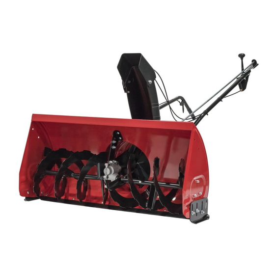
- Page 27 KNOW YOUR SNOW THROWER Read this owner's manual and safety rules before operating your snow thrower. Compare the illustration below with your snow thrower to familiarize yourself with the various controls and their locations. LIFT HANDLE UPPER CHUTE _f'_" LOWERCHUTE SCRAPER PLATE SPIRAL AUGERS, R.H.&...
- Page 28 RAISING ANDLOWERING • Toraise, p ushdownonthe lifthandle untilthesnow thrower l ocksinthe raised transport p osition. • Tolower, p ushdown slightly onthelifthandle andpull thetrigger. W iththetriggerpulled, s lowly lower the snow thrower u ntilit reaches t heground. CAUTION: Donotoperate thesnow thrower w ithout t he rearweight a ttached tothetractor t oprovide extra traction and stability REMOVING S NOW...
- Page 29 CAUTION: Before servicing oradjusting thesnow thrower s hut o fftheengine, r emove thespark plug wire(s), settheparking b rake andr_move t hekey from thetractor i gnition. REPLACING AUGER BELT • Disengage the tractor's attachment clutch. • Lower the snow thrower to the ground. Remove the attachment pin •...
- Page 30 STORAGE RECOMMENDATIONS Lower the snow thrower to the ground. Remove the snow thrower from the tractor. Clean the snow thrower thoroughly Wash off any salt deposit which may have dried on the thrower and housing Any bare metal that has become exposed should be painted or coated with a light oil to prevent rust Store in a dry place REMOVING...
- Page 31 NOTES...
- Page 32 NOTES...
- Page 33 NOTES...
- Page 34 REPAIR PARTS FOR MODEL 486.24838 42" SNOWTHROWER "55 21_. 40, 59...
- Page 35 REPAIR PARTS FOR MODEL 486.24838 PART DESCRIPTION 05931 Housing, Bearing 84184 Housing Assembly 818-0616 Gear Assembly 83579 Chute Crank Rod Assembly 83768 impeller Assembly 24773 Scraper Plate 703-2734 Bracket, Housing Brace 703-2735A Bracket, Chute Crank 24816 Cover, Belt 705-5226 Chute Reinforcement 708-5269 Spiral Assembly, L.H.
- Page 36 REPAIR PARTS FOR MODEL 486.24838 42" SNOWTHROWER 78_79 38 _...
- Page 37 REPAIR PARTS FOR MODEL 486.24838 PART DESCRIPTION 64637 Lift Shaft Assembly 710-0865 Hex Bolt, 1/2-13 x 1" 710-0367 Rex Bolt, 6/8-11 x 1-1/2" 711-0332 Pin, Bracket Lift 712-0261 Nut, Rex Lock 6/8-11 Thread 43262 Nut, Hex Lock 1/2-13 Pin, Cotter 1/8" x 3/4"...
- Page 38 REPAIR PARTS FOR MODEL 486.24838 "X 42" SNOWTHROWER PART NO. t 43080 43064 43083 43086 43081 25727 63904 24286 63762 43015 46981 43082 46982 738-0680 750-0466 750-0660 43003 714-0161 741-0919 08253B 15296A 14088B 44377 736-0247 43063 46989 48138 47846 47044...
- Page 39 SUGGESTED GUIDE FOR SIGHTING OF TRACTOR WiTH ATTACHMENT - - Lo 1, Fold this page along 2. Hold page before you so that trunk or other upright 3, Sight across the fold 4, Compare the angle SLOPES FOR SAFE OPERATION dotted line indicated above,...
- Page 40 For repair-in your lawn and garden no matter For the replacement owner's manuals For Sears professional and items like garage 1-800-4-MY-HOME Call anytime, www.sears.com For repair of carry-in and electronics, call or go on-line Sears Call anytime, To purchase or maintenance agreement 1-800-827-6655 Para...