Table of Contents
Advertisement
Operator's IVlanuai
CRRF r. MgN°
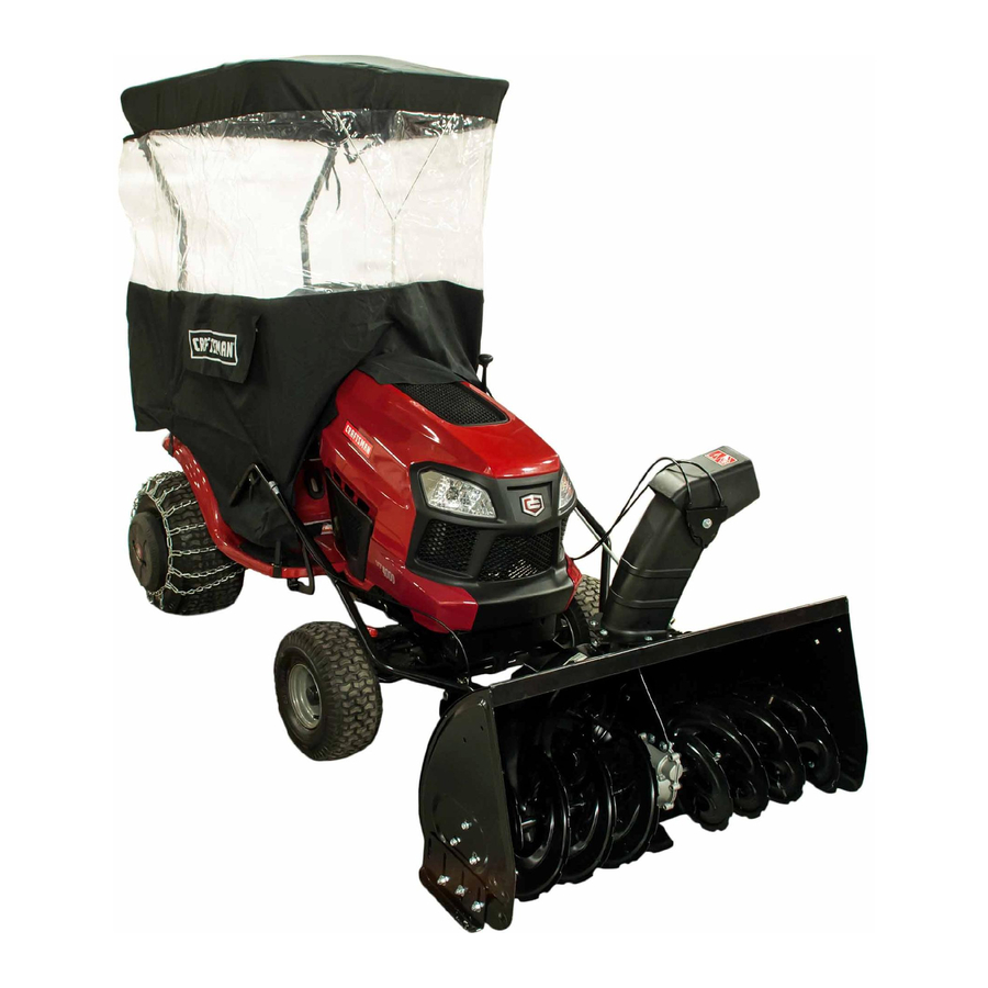
42"- 2 STAGE SNOW THROWER
TRACTOR ATTACHMENT
IVlodei No. 486.248371
DO NOT RETURN
TO STORE
For Missing Parts or Assembly
Questions
Call 1-866-576-8388
FOR TRACTORS
WITH MODEL NUMBERS
BEGiNNiNG
WITH 247.
CAUTION:
Before using this product, read
this manual and follow all Safety
Rules and Operating
Instructions.
,, Safety
,, Assembly
,, Operation
,, Maintenance
,, Parts
Sears, Roebuck
and Co., Hoffman
Estates, IL 60179 U.S.A.
www.sears.com/craftsman
PRINTED IN U.S.A.
FORM NO. 42317 (06/15/11)
Advertisement
Table of Contents

Related Manuals for Craftsman 486.248371


Summary of Contents for Craftsman 486.248371
- Page 1 Operator's IVlanuai CRRF r. MgN° 42"- 2 STAGE SNOW THROWER TRACTOR ATTACHMENT IVlodei No. 486.248371 FOR TRACTORS CAUTION: Before using this product, read this manual and follow all Safety Rules and Operating Instructions. Sears, Roebuck and Co., Hoffman www.sears.com/craftsman PRINTED IN U.S.A.
- Page 2 Sears, Roebuck and Co., D817WA, Hoffman Estates, IL 60179 These and other accessories are recommended for use with your unit. Call 1-800-4-MY-HOME® to find out if they are available. If available, they may be purchased at most Craftsman outlets or by calling 1-800-4-MY-HOME®. WHEEL WEIGHT The model number and serial numbers will be found on a decal attached to the snow thrower.
- Page 3 184045 199682 Do not place hands near rotating parts. Keep clear of the discharge opening at all times. • Never allow children to operate the equipment. Never allow adults to operate the equipment without proper instruction. Disengage all clutches and shift into neutral before starting engine.
- Page 4 43351 43020 49933 48106 46938 47630 49948 47631 43086 R19172410 712-3083 43019 HA21362 SHOWN ACTUAL SIZE 43840 43084 43350 710-0890A R19171616 43088 _\\\\\\ 44695 43082 47810 r--qq 43182 43063 43661 • JL 43682 44215 _ ... 43081 47605, 43070 27231 43003 46584 47598...
- Page 5 46959 43055 46963 IMPORTANT: Not all items supplied in the hardware bag will be needed for your particular tractor. Unneeded items may be discarded after you have completed assembly and checked operation of unit. DO NOT DISCARD the two spare shear bolts (K) and 5/16"...
- Page 6 Housing Assembly LiftHandle andCable Chute CrankRodAssembly Support Tube, C rank Rod V-Belt, D rive52"(#41353) V-Belt, D rive55"(#46989) Chute andControl C able Assembly Clutch IdlerAssembly Anti-rotation B racket 10. V-Belt, A uger(Attached t o Housing Assembly) 11. Frame Brace ONLY iTEMS NEEDED 12.
- Page 7 LOCATE TRACTOR'S MODEL Look under your tractor seat to locate the model number label shown below. This manual is for tractors with model numbers that start with 247 as shown below. 247 MODEL TRACTORS CRRFTSMgH ° CONFORMS ANSi B71,1=2003 SAFETY III |1 111111|1| IIIII|lilln,,,...,,, 111111111111 000000A000000...
- Page 8 STEP1: (SEEFIGURE 1) • Assemble a shoulder bolt and a 3/8" nylock nut to the holes shown on each side of the tractor frame. SHOULDER BOLT 3/8" NYLOCK NUT FIGURE 1 STEP 2: (SEE FIGURE 2) • Place a front mount plate onto each shoulder bolt and install two quick release pins as shown.
- Page 9 STEP5: (SEE FIGURE 5) • Remove the thread forming bolt from the hole in the footrest bracket on the left side of the tractor frame. • Attach the L.H. hanger bracket to the empty hole using a 5/16" x 1" hex bolt, a 5/16" lock washer, and a 5/16"...
- Page 10 STEP 9: (SEE FIGURE 9) • Assemble the two support tubes to the inside of each front frame bracket using a 1/2" x 1-1/2" hex bolt, a 1/2" spacer and a 1/2" nylock nut for each bracket. Do not tighten yet. 1/2"...
- Page 11 STEP13 (SEEFIGURE 13) • Assemble a 1/2"x 1"washer ontothebentendofa support l inkandtheninsert t hethreaded endintoa support t ubeandthebentendintotherearholein a frontmounting plate, A ssemble a nother 1 /2"x 1" washer o ntotheendofthelinkandsecure itwith a small 5 /64"hairpin cotter. R epeat fortheother support l ink.
- Page 12 ASSEMBLY OF THE SNOW THROWER STEP 15: (SEE FIGURE 15) • Place the lift handle into the lift bracket on the right side of the snow thrower. Fasten the handle to the bracket using two 5/16" x 1-3/4" hex bolts and 5/16" Nylock nuts.
- Page 13 STEP19: (SEEFIGURE 19) • Attach thechutecrankrodassembly b rackets t o theplasticbracket o nthe leftsideofthedischarge housing. Alignthechutecrankbracket b eneath the rodsupport b racket a ndassemble b othtotheplastic bracket u sing two5/16" x 1"carriage bolts,5/16" washers and5/16"Nylock nuts. D o nottightenyet. CHUTE CRANK 5/16"...
- Page 14 ATTACHING SNOW THROWER STEP 22: (SEE FIGURE 22) Place the snow thrower on a flat, level surface. Extend the auger belt out behind the snow thrower, leaving the belt assembled to the snow thrower pulleys. Roll the tractor up behind the snow thrower, centering it between the snow thrower's mounting plates.
- Page 15 THE ATTACHMENT STEP 25: (REFER BACKTO FIGURE 22 ON PAGE 14) Lift the front of the snow blower to align the holes in the mounting plates and the side plates. From the left side of the tractor insert the attachment pin through the holes.
- Page 16 KNOW YOU R SNOW TH ROWER Read this owner's manual and safety rules before operating your snow thrower. Compare the illustration below with your snow thrower to familiarize yourself with the various controls and their locations. LIFT HANDLE UPPER CHUTE LOWER CHUTE SCRAPER PLATE SPIRAL AUGERS, R.H.&...
- Page 17 RAISING ANDLOWERING • Toraise, p ushdownonthelifthandle untilthesnow thrower l ocksintheraised transport p osition. Tolower, p ushdown slightly onthelifthandle andpull thetrigger. W iththetriggerpulled, s lowly lower the snowthrower u ntilit reaches theground. CAUTION: Donotoperate thesnow thrower w ithout w heel w eights attached tothetractor t oprovide extra traction and stability.
- Page 18 CAUTION: Before servicing oradjusting thesnow thrower, shut o fftheengine, r emove thespark plug wire(s), settheparking b rake andremove t hekey from thetractor i gnition. REPLACING AUGER BELT • Disengage the tractor's attachment clutch. Lower the snow thrower to the ground. Remove the attachment pin.
- Page 19 STORAGE RECOMMENDATIONS • Lower the snow thrower to the ground. Remove the snow thrower from the tractor. Clean the snow thrower thoroughly. Wash off any salt deposit which may have dried on the thrower and housing. Any bare metal that has become exposed should be painted or coated with a light oil to prevent rust.
- Page 20 PROBLEM Spiral a ugers don'tturn Clogged discharge chute Snow thrower stalls tractor engine Front wheels slide instead of steering Snow thrower rides up over snow CAUSE 1.Upper or lower V belttooloose 2. Upper or lower V belt broken 3. Shear bolts are sheared. 1.
- Page 21 NOTES...
- Page 22 REPAIR PARTS FOR MODEL 486.248371 (For Tractors With Model Numbers Beginning 233_ 71- ._ 42" SNOW THROWER With 247)
- Page 23 REPAIR PARTS FOR MODEL 486.248371 (For Tractors With lVlodel Numbers Beginning PART NO 05931 Housing, Bearing 65701 Housing Assembly 71464 Gear Assembly 63579 Chute Crank Rod Assembly 63768 Impeller Assembly 24773 Scraper Plate 25982 Shaft, Auger Gearbox 703-2735A Bracket, Chute Crank...
- Page 24 REPAIR PARTS FOR MODEL 486.248371 42" SNOW THROWER (For Tractors With Model Numbers Beginning With 247) 3_... 59---_ C...
- Page 25 REPAIR PARTS FOR MODEL 486.248371 (For Tractors With lVlodel Numbers Beginning With 247) PART NO 64637 Lift Shaft Assembly 710-0865 Hex Bolt, 1/2-13 x 1" 710-0367 Hex Bolt, 5/8-11 x 1-1/2" 711-0332 Pin, Bracket Lift 712-0261 Nut, Hex Lock 5/8-11 Thread...
- Page 26 REPAIR PARTS FOR MODEL 486.248371 (For Tractors With Model Numbers Beginning PART NO DESCRiPTiON HA180132 Hex Bolt, 3/8-16 x 2-1/4" 43064 Hex Lock Nut, 5/16-18 43083 Hex Nut, 5/16-18 43086 Lock Washer, 5/16" 43182 Hex Bolt, 5/16-18 x 3/4" 26943...
- Page 27 SUGGESTED GUIDE FOR SIGHTING SLOPES FOR SAFE OPERATION OF TRACTOR WITH ATTACHMENT _FOLD ALONG 10 DEGREES WARNING: To avoid serious injury, operate your tractor up and down the face of slopes, never across the face. Do not operate & on slopes greater than 10 degrees. Make turns gradually to prevent tipping or loss of control.
- Page 28 For expert troubleshooting For repair - in your home - of all major brand appliances, lawn and garden equipment, no matter who made it, no matter who sold it! For the replacement owner's manuals that you need to do-it-yourself. For Sears professional and items like garage door openers and water heaters.