Table of Contents
Advertisement
Operator's Manual
42"- 2 STAGE SNOW THROWER
TRACTOR ATTACHMENT
Model No. 486.248381
CAUTION:
Before using this product, read
this manual and follow all Safety
Rules and Operating Instructions.
Sears, Roebuck and Co., Hoffman Estates, IL 60179 U.S.A.
www.sears.com/craftsman
PRINTED IN U.S.A.
®
STOP
DO NOT RETURN TO STORE
For Missing Parts or Assembly
Questions Call 1-866-576-8388
• Safety
• Assembly
• Operation
• Maintenance
• Parts
FORM NO. 40242 (06/27/08)
Advertisement
Table of Contents

Related Manuals for Craftsman 486.248381


Summary of Contents for Craftsman 486.248381
- Page 1 42"- 2 STAGE SNOW THROWER TRACTOR ATTACHMENT Model No. 486.248381 CAUTION: Before using this product, read this manual and follow all Safety Rules and Operating Instructions. Sears, Roebuck and Co., Hoffman Estates, IL 60179 U.S.A. www.sears.com/craftsman PRINTED IN U.S.A. ®...
-
Page 2: Table Of Contents
SERVICE AND ADJUSTMENTS ... 29 STORAGE ... 30 TROUBLESHOOTING ... 30 REPAIR PARTS ILLUSTRATION ... 34,36,38 REPAIR PARTS LIST... 35,37,38 SLOPE GUIDE ... 39 PARTS ORDERING/SERVICE ...BACK COVER WARRANTY TIRE CHAINS MODEL NUMBER: SERIAL NUMBER: DATE OF PURCHASE: SNOW CAB 71-24276 486.248381 __________________ __________________... - Page 3 Any power equipment can cause injury if operated improperly or if the user does not understand how to operate the equipment. Exercise caution at all times, when using power equipment. • Read this owner's manual carefully and know how to operate your snow thrower and how to stop the unit and disengage the controls quickly.
- Page 4 HARDWARE PACKAGE CONTENTS SHOWN ACTUAL SIZE NOT SHOWN ACTUAL SIZE...
- Page 5 REF. QTY. DESCRIPTION Hex Bolt, 1/2" x 1-1/4" Hex Bolt, 3/8" x 3-1/4" Hex Bolt, 3/8" x 1" Hex Bolt, 5/16" x 1-3/4" Hex Bolt, 5/16" x 3/4" Hex Bolt, 1/4" x 1" Hex Bolt, 3/8" x 1" (Thread Forming) Hex Bolt, 3/8"...
-
Page 6: Carton Contents
Cross Brace (Weight Tray) Side Braces (2) (Weight Tray) Left Hand Side Plate Right Hand Side Plate Anti-rotation Bracket Engagement Rod (Not used on some models) Suspension Arms (2) Engine Pulley Keeper (Not used on some models) Chute Crank Rod Assembly Support Tube, Crank Rod Lift Handle and Cable Cable Bracket... -
Page 7: Assembly
TOOLS REQUIRED FOR ASSEMBLY (2) 7/16" Wrenches (2) 1/2" Wrenches (2) 9/16" Wrenches (2) 3/4" Wrenches (1) Screw Driver (1) Knife ADDITIONAL ITEMS REQUIRED General Purpose Grease REMOVAL OF PARTS FROM CARTON • Remove all parts and hardware packages from the carton. Lay out parts and hardware and identify using the illustrations on pages 4 and 6. - Page 8 INSTALL SIDE PLATES STEP 3: (SEE FIGURE 3) • Fasten the R.H. Side Plate (bend facing out) to the front three holes in the tractor frame using three 3/8" x 1" carriage bolts (K), three 1/2" washers (V) (see note) and three 3/8" flange nuts (BB). For the rear hole, use a 5/16" x 1" carriage bolt (N), a 1/2" washer (V) and a 5/16"...
- Page 9 THIS SECTION IS FOR TRACTORS WITH A MANUAL ATTACHMENT CLUTCH If your tractor has an electric attachment clutch go to step 14 on page 11. STEP 7: (SEE FIGURE 7) • Attach the pulley (long end of hub facing down) and the large spacer (SS) to the hole shown in the clutch/ idler assembly.
- Page 10 STEP 11: (SEE FIGURE 11) • Find the cable clip that is attached to the left side of the tractor frame underneath the footrest. Open the clip and remove the mower clutch cable. Do not remove the clip from the tractor frame. The cable reattaches to the clip when using the mower deck. • Move the attachment clutch lever on the dash panel to the disengaged position. • Place the clutch/idler assembly on the floor on the left side of the tractor.
- Page 11 THIS SECTION IS FOR TRACTORS WITH AN ELECTRIC ATTACHMENT CLUTCH STEP 14: (SEE FIGURE 14) • Attach the two suspension arms to the rear of the clutch/idler assembly using two 5/16" x 3/4" hex bolts (E) and 5/16" nylock nuts (CC) for each arm. Place the arms on the outside of the frame with the notches to the rear.
- Page 12 STEP 18: (SEE FIGURE 17) • Turn the clutch/idler assembly right side up. • Slightly loosen the hex bolt next to the flat idler pulley. Install the drive belt down between the hex bolt and the flat idler pulley with the flat side of the belt against the pulley. Retighten the hex bolt. • Loop the belt around the large v-pulley, placing it between the v-pulley and the hex bolt next to the pulley. HEX BOLTS DRIVE BELT FIGURE 17 Did you choose the correct drive belt for STOP your tractor? Using the wrong length belt may cause premature bearing or belt failure. STEP 19: (SEE FIGURE 18) • Attach the clutch/idler assembly to the tractor frame.
- Page 13 INSTRUCTIONS FOR TRACTORS WITH DUAL FRONT DECK SUSPENSION BRACKETS FASTEN SIDE PLATES TO TRACTOR f your tractor resembles figure 20, go to step 21. If your tractor resembles figure 22, go to step 23. STEP 21: (SEE FIGURE 20) • Remove bolts from front three holes shown. • If a bolt is present in the fourth hole, replace it with a 5/16" x 1" carriage bolt (N) without a nut. The bracket fastened to inside of frame must remain in place. REPLACE BOLT (IF PRESENT) REMOVE BOLTS...
- Page 14 INSTALLING HANGER BRACKETS For better clearance, lower the tractor's suspension arms using the attachment lift lever. STEP 26: (SEE FIGURE 25 or 26) On Tractors With Foot Rest Brackets • Remove the bolt and nut that fasten the L.H. and R.H. foot rest brackets to the frame. • Attach the L.H. Hanger Bracket (marked "L") to the inside of the tractor frame using two 3/8" x 1" carriage bolts (K) and 3/8" flanged nuts (BB). Bolt heads go on inside of tractor frame.
- Page 15 INSTALLING CLUTCH/IDLER ASSEMBLY This section covers the installation of the Clutch/Idler assembly to tractors with attachment clutches that are either rod operated (p. 15), cable operated (p. 17) or electric (p. 19). Use the appropriate instructions for your tractor. ROD OPERATED MANUAL ATTACHMENT CLUTCH STEP 29: (SEE FIGURE 29) • Move the attachment clutch lever on the dash panel to the disengaged (down) position.
- Page 16 STEP 32: (SEE FIGURE 32) • Be sure to lift up the front end of the engagement rod as shown when performing the next operation. You can temporarily support the rod using a rubber band tied to the engine pulley keeper. • Attach the clutch/idler assembly to the tractor frame as follows. Hook the assembly's notched arms onto the two shoulder bolts you assembled to the inside of the tractor frame.
- Page 17 CABLE OPERATED MANUAL ATTACHMENT CLUTCH STEP 35: (SEE FIGURE 35) • Attach the two suspension arms to the inside of the clutch/idler assembly using two 5/16" x 3/4" hex bolts (E), 5/16" washers (U) and 5/16" nylock nuts (CC) for each arm. Place the washers between the arms and the assembly frame.
- Page 18 STEP 39: (SEE FIGURE 39) • Remove the engine pulley keeper from the side of the tractor frame by removing the washer and nut that secure the keeper. Attach the new pulley keeper supplied with the snow thrower, reusing the original bolt, washer and nut. NOTE: Some tractors may already be equipped with a pulley keeper that is identical to the new one supplied. • Attach the clutch/idler assembly to the tractor frame as follows. Hook the assembly's notched arms onto the two shoulder bolts you assembled to the inside...
- Page 19 ELECTRIC ATTACHMENT CLUTCHES STEP 41: (SEE FIGURE 41) • Attach the two suspension arms to the inside of the clutch/idler assembly using two 5/16" x 3/4" hex bolts (E), 5/16" washers (U) and 5/16" nylock nuts (CC) for each arm. Place the washers between the arms and the assembly frame. • Insert a tensioning chain through the hole shown and attach the end link to the spring on the lower idler arm.
- Page 20 STEP 45: (SEE FIGURE 44) • Turn the clutch/idler assembly right side up. • Slightly loosen the hex bolt next to the flat idler pulley. Install the drive belt down between the hex bolt and the flat idler pulley with the flat side of the belt against the pulley. Retighten the hex bolt. • Loop the belt around the large v-pulley, placing it between the v-pulley and the hex bolt next to the pulley. Place the belt to the inside of the other flat idler pulley. HEX BOLTS DRIVE BELT FIGURE 44 Did you choose the correct drive belt for STOP your tractor? Using the wrong length belt may cause premature bearing or belt failure. STEP 46: (SEE FIGURE 45) • Attach the clutch/idler assembly to the tractor frame as follows. Hook the assembly's notched arms onto...
- Page 21 ASSEMBLY OF THE SNOW THROWER STEP 48: (SEE FIGURE 47) • Place the lift handle into the lift bracket on the right side of the snow thrower. Fasten the handle to the bracket using two 5/16" x 1-3/4" hex bolts (D) and 5/16" Nylock nuts (CC). 5/16" NYLOCK NUT (CC) FIGURE 47 NOTE: Be sure the lift release cable's plastic covering stays inserted into the trigger assembly for the next step.
- Page 22 STEP 52: (SEE FIGURE 51) • Attach the chute crank rod assembly brackets to the plastic bracket on the left side of the discharge housing. Align the chute crank bracket beneath the rod support bracket and assemble both to the plastic bracket using two 5/16" x 1" carriage bolts (N), 5/16" washers (U) and 5/16"...
- Page 23 ATTACHING SNOW THROWER TO TRACTOR NOTE: An additional person's help may be required to mount the snow thrower to the front of the tractor. STEP 55: (SEE FIGURE 54) • Place the tractor and snow thrower on a flat, level surface so that the tractor can be rolled forward to attach the snow thrower. • Remove the Attachment Pin from the snow thrower. • Extend the auger belt out behind the snow thrower, making sure the belt is still looped over the top of the large drive pulley and underneath the two idler pulleys.
- Page 24 INSTALLING THE ATTACHMENT PIN STEP 58: (REFER BACK TO FIGURE 54 ON PAGE 23) • Lift the front of the snow blower to align the holes in the mounting plates and the side plates. From the left side of the tractor insert the attachment pin through the holes. Secure it with by reinstalling the 1/8" hairpin cotter (KK).
- Page 25 ATTACHING TO (GT) GARDEN TRACTORS WITH A SINGLE FRONT DECK SUSPENSION BRACKET STEP 61: (SEE FIGURE 59) • Locate the upper empty hole in the right side of the tractor's draw bar. Insert a 3/8" x 1" hex bolt (C) from inside the tractor frame through the hole. Hook the slotted end of a side brace down onto the bolt, then assemble a 3/8" flanged nut (BB) onto the bolt making only finger tight.
- Page 26 ALTERNATE INSTRUCTIONS FOR WEIGHT TRAY STEP 63: (SEE FIGURE 61) • Block up the rear of the tractor to allow removal of rear wheels. • Remove the rear wheels from the axle, retaining the square key and all other parts for reassembly. • Remove the hex bolt from the top hole in the side of the tractor frame. If no bolt is present and the hole is unthreaded, screw a 3/8" x 3/4" self threading bolt (H) into and out of the hole to create threads.
-
Page 27: Safety Rules
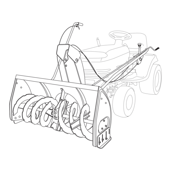
KNOW YOUR SNOW THROWER Read this owner's manual and safety rules before operating your snow thrower. Compare the illustration below with your snow thrower to familiarize yourself with the various controls and their locations. LIFT HANDLE UPPER CHUTE LOWER CHUTE SCRAPER PLATE SPIRAL AUGERS, R.H. & L.H. CHUTE TILT HANDLE Pivots the Upper Chute up or down to control the angle and distance of discharge. CRANK ROD Rotates the Lower and Upper Chutes to control the direction of discharge. -
Page 28: Maintenance
RAISING AND LOWERING • To raise, push down on the lift handle until the snow thrower locks in the raised transport position. • To lower, push down slightly on the lift handle and pull the trigger. With the trigger pulled, slowly lower the snow thrower until it reaches the ground. CAUTION : Do not operate the snow thrower without the rear weight attached to the tractor to provide extra traction and stability. -
Page 29: Service And Adjustments
CAUTION : Before servicing or adjusting the snow thrower, shut off the engine, remove the spark plug wire(s), set the parking brake and remove the key from the tractor ignition. REPLACING AUGER BELT • Disengage the tractor's attachment clutch. • Lower the snow thrower to the ground. • Remove the attachment pin. • Lock the snow thrower's lift handle in the down position to decrease belt tension. • Release the spring tension from the auger belt idler arm on the bottom of the clutch/idler assembly. • Remove the auger drive belt from the clutch/idler assembly and from the spiral auger housing. -
Page 30: Storage
STORAGE RECOMMENDATIONS • Lower the snow thrower to the ground. • Remove the snow thrower from the tractor. • Clean the snow thrower thoroughly. Wash off any salt deposit which may have dried on the thrower and housing. • Any bare metal that has become exposed should be painted or coated with a light oil to prevent rust. • Store in a dry place. REMOVING THE SPIRAL AUGER HOUSING • Lower the snow thrower to the ground. • Remove the attachment pin. See figure 54 on page • Lock the snow thrower's lift handle in the down position to decrease belt tension. • Release the spring tension from the auger belt idler arm on the bottom of the clutch/idler assembly. • Remove the auger drive belt from the clutch/idler assembly. See figure 56 on page 23. - Page 31 NOTES...
- Page 32 NOTES...
- Page 33 NOTES...
- Page 34 PARTS REPAIR PARTS FOR MODEL 486.248381 42" SNOW THROWER...
- Page 35 REPAIR PARTS FOR MODEL 486.248381 42" SNOW THROWER PART NO QTY 05931 Housing, Bearing 65701 Housing Assembly 71464 Gear Assembly 63579 Chute Crank Rod Assembly 63768 Impeller Assembly 24773 Scraper Plate 25982 Shaft, Auger Gearbox 703-2735A Bracket, Chute Crank 24816...
- Page 36 REPAIR PARTS FOR MODEL 486.248381 42" SNOW THROWER 76 61...
- Page 37 REPAIR PARTS FOR MODEL 486.248381 42" SNOW THROWER PART NO QTY 64637 Lift Shaft Assembly 710-0865 Hex Bolt, 1/2-13 x 1" 710-0367 Hex Bolt, 5/8-11 x 1-1/2" 711-0332 Pin, Bracket Lift 712-0261 Nut, Hex Lock 5/8-11 Thread 43262 Nut, Hex Lock 1/2-13 Pin, Cotter 1/8"...
- Page 38 REPAIR PARTS FOR MODEL 486.248381 42" SNOW THROWER PART NO QTY DESCRIPTION 43080 Carriage Bolt, 5/16-18 x 3/4" 43064 Hex Lock Nut, 5/16-18 43083 Hex Nut, 5/16-18 43086 Lock Washer, 5/16" 43081 Washer, 5/16" Std. Wrt. 25727 Frame, Clutch and Pulley...
- Page 40 Get it fixed, at your home or ours! Your Home For expert troubleshooting and home solutions advice: www.managemyhome.com For repair – in your home – of all major brand appliances, lawn and garden equipment, or heating and cooling systems, no matter who made it, no matter who sold it! For the replacement parts, accessories and owner’s manuals that you need to do-it-yourself.