Advertisement
Quick Links
installation and
servicing
Vanguard L
Your Ideal installation and servicing guide
Models 170 - 3500
When replacing any part on this appliance, use only spare parts that you can be
assured conform to the safety and performance specification that we require. Do not
use reconditioned or copy parts that have not been clearly authorised by Ideal Boilers.
ENGINEERED FOR PEACE OF MIND
Advertisement

Related Manuals for IDEAL Vanguard L


Summary of Contents for IDEAL Vanguard L
- Page 1 When replacing any part on this appliance, use only spare parts that you can be assured conform to the safety and performance specification that we require. Do not ENGINEERED FOR PEACE OF MIND use reconditioned or copy parts that have not been clearly authorised by Ideal Boilers.
- Page 2 It could also infringe the Gas Safety Regulations and the above regulations. Assembly and Installation Instructions for Ideal Vanguard L heating boilers should be read in conjunction with the general technical data tables enclosed and any other technical publication supplied with the burner.
- Page 3 Installation............... 13 Performance Data............2 INTRODUCTION Positioning of the Turbulators......... 9 The Vanguard L boilers are a range of steel shell pressure jet boilers offering high efficiency operation, ease of maintenance, Servicing................. 31 fuel flexibility and low emissions.
- Page 4 Heating boilers with forced draught burners with atomizing oil burners. Assembly and Installation Instructions for Ideal Vanguard L heating boilers should be read in conjunction with the general technical data tables enclosed and any other technical publication supplied with the burner.
- Page 5 Even the water in closed systems will promote calorifier MUST be of the indirect type. corrosion unless treated. For the reason stated, Caradon Ideal The appliances are NOT suitable for gravity central heating nor Limited strongly recommend that when necessary the systems are they suitable for the provision of gravity domestic hot water.
- Page 6 GENERAL BOILER WATER CONNECTIONS The Vanguard L boilers are provided with flanged connections for both flow and return. Dimensions vary depending on the boilers output and details can be found in the General Data Table on page 4. The boiler shell is also provided with separate connections for a drain and safety valve.
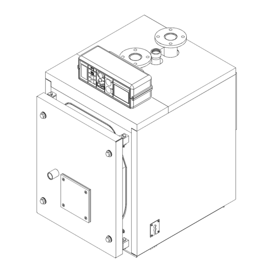
- Page 7 GENERAL BOILER DIMENSIONS CONT'D Vanguard L 760 - 970 van 5655 1. Control Panel T1. Flow connection 2. Burner mating flange with gasket T2. Return connection 3. Flue collector hood cleaning door T3. Safety valve and expansion connection 4. Flame inspection tube with pressure test T4.
- Page 8 GENERAL BOILER DIMENSIONS CONT'D Vanguard L 1100 - 2650 van 5656 Vanguard L 3000 - 3500 T1. Flow connection T5. Flue connection 1. Control Panel 2. Burner mating flange with gasket T2. Return connection T6. Burner connection T3. Safety valve and expansion connection T7.
- Page 9 200mm plus the burner projection to allow the burner door to be swung open and maintain access to the rear. In multiple installations consideration must also be given to the burner door hinge position and consequent clearance. Vanguard L - Installation & Servicing...
- Page 10 GENERAL OPEN VENTED SYSTEM - minimum static head requirements The Vanguard L boiler has a minimum static head 4. The boiler is at the highest point of the system. Systems requirement of 2.5 metres (8 feet approx.) depending on the designed to rise above the flow connections will, of course, particular characteristics of the system design (see diagram).
- Page 11 Where such a fan is already fitted (or if it is intended to fit an in excess of 60 kW extractor fan after installation of the appliance) the advice of the total rated input gas supplier should be obtained. Vanguard L - Installation & Servicing...
- Page 12 Refer to applicable regulations while determining the size and must respect the usual precautions (dilution, piping, 'T' for height of the flue. Please note that Vanguard L boilers have removal of condensation) in order to prevent deterioration of pressurised and sealed combination chambers and that the the chimney.
- Page 13 Rear Right Side Jacket Rear Left Side Jacket Rear Insulation Rear Body Insulation Central Body Insulation Box Code Central Side Jacket Central Right Side Jacket Central Left Side Jacket Central Body Insulation Rear Body Insulation Vanguard L - Installation & Servicing...
- Page 14 Literature Pack (all models) • Ideal Installation and Servicing Instructions • Ideal User's Instructions • Ideal Data Plate • Ideal Log Book - Pressure Jet • Ideal Warranty Literature • Ideal Casing Badge • 7 Pole Burner Plug • 4 Pole Burner Plug •...
- Page 15 15 CASING ASSEMBLY Vanguard L 170 to 630 E. Fit the 'Ideal' badge to the front edge of the front top panel For boiler models 170 to 510 the casing and insulation are (10) and secure with the rubber fixings.
- Page 16 INSTALLATION 16 POSITION OF THERMOMETER/THERMOSTAT SENSOR IN THE BULB HOLDER Vanguard L 170 to 970 LEGEND 1. Thermometer bulb 2. Operation thermostat bulb 3. Safety thermostat bulb 4. Minimum temp. thermostat bulb 5. Sensor retaining clip 6. Contact spring Vanguard L -...
- Page 17 INSTALLATION 17 CASING ASSEMBLY Vanguard L 760 to 970 E. Fit the 'Ideal' badge to the front edge of the front top panel For these boiler models the casing and insulation are (12) and secure with the rubber fixings. contained in 3 cartons.
- Page 18 (8) to it. Data plate and ventilation requirements labels are in the plastic bag containing the documents. E. Fit the 'Ideal' badge to the front edge of the front top panel (9) and secure with the rubber fixings. 4a 5 Vanguard L - Installation &...
- Page 19 E. Fit the 'Ideal' badge to the front edge of the front top panel (8) and secure with the rubber fixings. Data plate and ventilation requirements labels are in the plastic bag containing the documents.
- Page 20 INSTALLATION 20 CASING ASSEMBLY Vanguard L 3000 to 3500 D. Fit the control panel board to the left or right front side For these boiler models the casing and insulation are panel. Remove the upper shell of the control panel and contained in 3 cartons.
- Page 21 INSTALLATION 21 POSITION OF THE THERMOMETER/THERMOSTAT SENSORS IN THE BULB HOLDER Vanguard L 1100 to 3500 Insert the sensors in the bulb holder in the upper part of the boiler, in the following order: 1. Thermometer 2. Operating (H/L) thermostat 3.
- Page 22 INSTALLATION 22 DOOR ASSEMBLY - VANGUARD L 170 to 630 MODELS The combustion chamber door is fitted with four fixing points, two on the left hand side which are normally used as hinges. The right hand side fixings are made with fastening bolts.
- Page 23 INSTALLATION 24 DOOR ASSEMBLY - VANGUARD L 1100 to 3500 The combustion chamber door is fitted with four fixing points, two on the left hand side which are normally used as hinges. The right hand side fixings are made with fastening bolts.
- Page 24 Details and Burner Door advice, relating to the use of L.P.G. for firing the Ideal Vanguard L range of boilers, are available on request to Caradon Ideal Ltd. Burner doors have been pre-drilled to match the standard burners offered.
- Page 25 27 INTERNAL WIRING DIAGRAM The control panel provided with the Vanguard L range is complete with a 7 way burner cable. A 4 way cable (for 2 stage burners) and the 7 and 4 pole plugs are in the literature pack.
- Page 26 No. printed on cable van 5724 29 HEATING PUMP OVERRUN The heating pump overrun is controlled by the minimum temperature thermostat. 30 FUEL OIL OR GAS CONNECTIONS Refer to the instructions supplied with the burner. Vanguard L - Installation & Servicing...
- Page 27 ON/OFF operation. For boilers fitted with high/low burners the thermostat also incorporates a feature which automatically controls the burner changeover from high fire to low fire at a fixed 6º below the flow temperature setting (i.e. 44ºC - 84ºC). Vanguard L - Installation & Servicing...
- Page 28 INSTALLATION 32 POSITIONING OF THE TURBULATORS The Vanguard L boilers are designed to be used in an output range to improve the seasonal efficiency and the possibility to be adopted in all the heating installations. The output must be adjusted at the...
- Page 29 Instructions and Log book to the customer and request him to Recommend that a contract for this work should be made with keep them in a safe place for ready reference. a CORGI registered heating installer for gas fired boilers. Vanguard L - Installation & Servicing...
- Page 30 Check the gas rate and measure the combustion CO/ content. IMPORTANT. After completing the servicing or replacement of components always: • Complete the boiler log book. • Test for gas soundness • Carry out functional checks as appropriate. Vanguard L - Installation & Servicing...
- Page 31 10. Thoroughly clean the flue tubes and turbulators. Caradon Ideal Limited does not accept any liability resulting 11. Remove the rear cleanout covers and dispose of the from the use of unauthorised parts or the repair and servicing debris/soot that may have accumulated.
- Page 32 Technical Training The Ideal Boilers Technical Training Centre offers a series of first class training courses for domestic, commercial and industrial heating installers, engineers and system specifiers. For details of courses please ring: ..01482 498 432 Ideal Boilers, P.O. Box 103, National Ave, Kingston upon Hull, HU5 4JN.