
Related Manuals for IDEAL COMBI ESP 24


Summary of Contents for IDEAL COMBI ESP 24
- Page 1 NEW BUILD YOUR COMPLETE SOLUTION. IDEAL BOILER STELRAD CYLINDER SOLAR RADIATOR PANEL FREE DESIGN DESIGN 364 DAYS STAGE SAP SERVICE A YEAR (USUALLY £50) WWW.IDEALBOILERS.COM...
- Page 2 WELCOME TO FIRST CLASS. OUR AWARD WINNING BOILERS GO THROUGH 200 QUALITY CHECKS BEFORE THEY LEAVE THE FACTORY, AND ARE AVAILABLE WITH A RANGE OF FLEXIBLE WARRANTY OPTIONS. YOU CAN REST ASSURED RELIABILITY IS GUARANTEED WHEN YOU PARTNER WITH IDEAL.
-
Page 3: Table Of Contents
CONTENTS. THE IDEAL PRODUCT RANGE LOGIC COMBI ESP LOGIC CODE COMBI ES LOGIC SYSTEM LOGIC HEAT BOILER CONTROLS LPG CONVERSION KITS FLUE SITING FLUEING OPTIONS CONTACT US... -
Page 4: The Ideal Product Range
THE IDEAL PRODUCT RANGE. Representing the next generation in heating design, the Logic range of boilers offers state-of-the-art technology in a practical, compact unit that fi ts easily into any standard kitchen cupboard. Available in a range of outputs, the Logic range comes complete with a fl... - Page 5 LOGIC COMBI ESP A high effi ciency combination boiler with a competitive SAP effi ciency score, particularly benefi cial for small, social new build properties. LOGIC CODE COMBI ES A simple one box solution, capable of supporting up to level 4 of the code for sustainable homes with built in fl...
-
Page 6: Logic Combi Esp
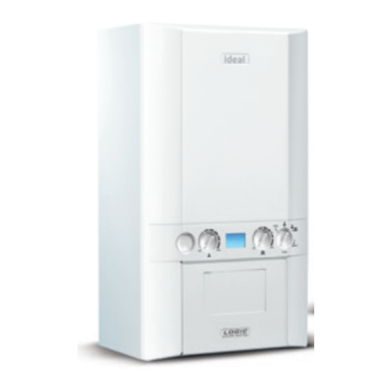
LOGIC COMBI ESP 24 30 35. HIGH EFFICIENCY COMBINATION BOILERS. Optimised for new build compliance following the SAP 2009/2012 design procedure, the Logic Combi ESP achieves improved SAP effi ciency scores and is particularly benefi cial for new build properties. - Page 7 FEATURES. COMPACT DIGITAL FROST FLUE CLASS 5 DISPLAY PROTECTION VARIANTS CONVERSION* SPECIFICATION. • Complete range of Logic combination EASY TO INSTALL boilers for new build developers • Compact cupboard fi t • Achieves improved SAP and DER ratings • Fast fi x fl ues for standard combination boiler usage •...
- Page 8 Height: 700mm Width: 395mm *Bottom clearance after installation can be reduced to Depth: 278mm 5mm. However, 100mm is required for servicing. FLUE LENGTHS. COMBI ESP 24 COMBI ESP 30 COMBI ESP 35 Max horizontal** Max vertical** 7.5m 7.5m 7.5m...
-
Page 9: Technical Specification
TECHNICAL SPECIFICATION. COMBI ESP 24 COMBI ESP 30 COMBI EPS 35 Weight (packaged) kg 36.3 36.5 36.5 Max installation weight kg 31.8 32.0 32.0 CH output (kW) min/max 4.8 - 24.2 6.1 - 24.2 7.1 - 24.2 @ 70°C CH output (kW) min/max 5.1 - 25.6... -
Page 10: Troubleshooting
See boiler “Fault Codes” section. If ‘0’ is displayed then contact Ideal Customer Services Helpline if your appliance is under warranty or a Gas Safe Registered Engineer, in IE a Registered... - Page 11 NO CENTRAL HEATING NO HOT WATER OR CENTRAL HEATING Check the mains switch (fused spur) is turned on and ensure Check the fused spur is switch mode control knob (D) (Control Panels: P.38) is in the turned on and ensure winter position switch mode control knob (D) (Control...
-
Page 12: Fault Codes
1. Turn power off and on at the fused spur. 15 minutes 2. If the boiler fails to operate please contact Ideal (if under warranty) or alternatively a Gas Safe Registered Engineer if outside of the warranty period. In IE contact a Registered Gas Installer RGII). - Page 13 2. If other appliances do not work or there are no other appliances, check the gas supply is on at the meter and/or pre payment meter has credit. If the boiler fails to operate then please contact Ideal (if under warranty) or alternatively a Gas Safe Registered Engineer if outside of the warranty period.
-
Page 14: Logic Code Combi Es
COMBI ES 26 33 38. HIGH EFFICIENCY COMBINATION BOILERS. Designed to take the headache out of meeting Building Regulations, the Logic Code Combi ES from Ideal is a simple one-box solution, capable of supporting up to level 4 of the Code for Sustainable Homes. - Page 15 FEATURES. COMPACT DIGITAL FROST FLUE CLASS 5 DISPLAY PROTECTION VARIANTS CONVERSION* SPECIFICATION. • Complete range of Logic combination EASY TO INSTALL boilers for new build developers • One single appliance to install – quick • Achieves optimum SAP and DER ratings and easy for standard combination boiler usage •...
- Page 16 CLEARANCES AND DIMENSIONS. DIMENSIONS IN MM Note: The minimum front clearance when built in to a cupboard is 5mm from the cupboard door but 450mm overall clearance with the cupboard door open is DIMENSIONS: required for servicing. Height: 830mm Width: 395mm *Bottom clearance after installation can be reduced Depth: 278mm to 5mm.
- Page 17 TECHNICAL SPECIFICATION. CODE COMBI CODE COMBI CODE COMBI ES 26 ES 33 ES 38 Weight (packaged) kg 39.5 39.7 39.7 Max installation weight kg 34.7 34.9 34.9 CH output (kW) min/max 4.8 - 24.2 6.1 - 24.2 7.1 - 24.2 @ 70°C CH output (kW) min/max 5.1 - 25.6...
- Page 18 See boiler “Fault Codes” section. If ‘0’ is displayed then contact Ideal Customer Services Helpline if your appliance is under warranty or a Gas Safe Registered Engineer, in IE a Registered...
- Page 19 NO CENTRAL HEATING NO HOT WATER OR CENTRAL HEATING Check the mains switch (fused spur) is turned on and ensure switch mode control knob (D) Check the fused spur is (Control Panels: P.38) is in the turned on and ensure winter position switch mode control knob (D) (Control...
- Page 20 No water flow Reset the appliance - if the boiler fails to operate then please thermistor contact Ideal (if under warranty) or alternatively a Gas Safe Registered Engineer if outside of the warranty period. In IE contact a Registered Gas Installer (RGII).
- Page 21 1. Turn power off and on at the fused spur. 15 minutes 2. If the boiler fails to operate please contact Ideal (if under warranty) or alternatively a Gas Safe Registered Engineer if outside of the warranty period. In IE contact a Registered Gas Installer (RGII).
-
Page 22: Logic System
LOGIC SYSTEM 15 18 24 30. HIGH EFFICIENCY SYSTEM BOILERS. The Logic System range of appliances from Ideal provide a simple and reliable solution for a wide variety of sealed domestic systems. - Page 23 FEATURES. COMPACT DIGITAL FROST FLUE CLASS 5 DISPLAY PROTECTION VARIANTS CONVERSION** SPECIFICATION. • Digital display and simple diagnostics EASY TO INSTALL • Fully modulating operation down • Compact cupboard fi t • Wide range of fl ueing options to 4.8 kW* •...
- Page 24 CLEARANCES AND DIMENSIONS. DIMENSIONS IN MM Note: The minimum front clearance when built in to a cupboard is 5mm from the cupboard door but 450mm overall clearance with the cupboard door open is DIMENSIONS: required for servicing. Height: 700mm Width: 395mm *Bottom clearance after installation can be reduced to Depth: 278mm 5mm.
- Page 25 TECHNICAL SPECIFICATION. SYSTEM 15 SYSTEM 18 SYSTEM 24 SYSTEM 30 Weight (packaged) kg 34.1 34.1 34.1 34.1 Max installation weight kg 27.7 27.7 27.7 27.7 CH output (kW) min/max 4.8 - 15.0 4.8 - 18.0 4.8 - 24.2 6.1 - 30.3 @ 70°C CH output (kW) min/max 5.1 - 15.9...
- Page 26 TROUBLESHOOTING. POINTS FOR THE NO HOT WATER BOILER USER Note. In line with our current warranty Check the mains switch (fused policy we would ask that you check spur) is turned on and ensure mode through the following guide to identify any control knob (B) (Control Panels: P.39) problems external to the boiler prior to is in the ON position...
- Page 27 NO CENTRAL HEATING Does the boiler operate and provide central heating? Check the mains switch (fused spur) is turned on and ensure mode control knob (B) (Control Check the time settings on the Panels: P.39) is in the programmer are as you require ON position and adjust if necessary Check the programmer is in...
- Page 28 1. Turn power off and on at the fused spur. minutes 2. If the boiler fails to operate please contact Ideal (if under warranty) or alternatively a Gas Safe Registered Engineer if outside of the warranty period. In IE contact a Registered Gas Installer (RGII).
- Page 29 2. If other appliances do not work or there are no other appliances, check the gas supply is on at the meter and/or pre payment meter has credit. If the boiler fails to operate then please contact Ideal (if under warranty) or alternatively a Gas Safe Registered Engineer if outside of the warranty period.
-
Page 30: Logic Heat
LOGIC HEAT 12 15 18 24 30. HIGH EFFICIENCY HEAT BOILERS. Designed to be installed with the minimum of fuss, Logic appliances offer a speedy installation. - Page 31 FEATURES. COMPACT DIGITAL FROST FLUE DISPLAY PROTECTION VARIANTS DIRECT CLASS 5 CONVERSION* REAR FLUE SPECIFICATION. EASY TO INSTALL • Fully modulating operation down to 4.8 kW** • Compact cupboard fi t • Weather compensation kit option • Direct 80mm diameter rear fl ue option •...
- Page 32 CLEARANCES AND DIMENSIONS. DIMENSIONS IN MM Note: The minimum front clearance when built in to a cupboard is 5mm from the cupboard door but 450mm overall clearance with the cupboard door open is required for servicing. DIMENSIONS: Height: 700mm *Bottom clearance after installation can be reduced Width: 395mm to 5mm.
- Page 33 TECHNICAL SPECIFICATION. HEAT 12 HEAT 15 HEAT 18 HEAT 24 HEAT 30 Weight (packaged) kg 28.5 28.5 28.5 28.5 28.5 Max installation weight kg 22.8 22.8 22.8 22.8 22.8 CH output (kW) min/max 4.8 - 12.0 4.8 - 15.0 4.8 - 18.0 4.8 - 24.2 6.1 - 30.3 @ 70°C...
- Page 34 TROUBLESHOOTING. POINTS FOR THE BOILER USER Note. In line with our current warranty policy we would ask that you check through the following guide to identify any problems external to the boiler prior to requesting a service engineer visit. Should the problem be found to be other than with the appliance we reserve the right to levy a charge for the visit, or for any pre-arranged visit where access is not gained by the engineer.
- Page 35 ACTION BCC activation fault Reset the appliance - if the boiler fails to operate then please contact Ideal (if under warranty) or alternatively a Gas Safe Registered Engineer if outside of the warranty period. In IE contact a Registered Gas Installer (RGII).
- Page 36 Fan fault Reset the appliance - if the boiler fails to operate then please contact Ideal (if under warranty) or alternatively a Gas Safe Registered Engineer if outside of the warranty period. In IE contact a Registered Gas Installer (RGII).
- Page 37 Flow temperature Check system pressure is between 1 & 1.5bar on the pressure overheat gauge. If the boiler fails to operate then please contact Ideal (if under warranty) or alternatively a Gas Safe Registered Engineer unconfigured PCB if outside of the warranty period. In IE contact a Registered Gas Installer (RGII).
-
Page 38: Boiler Controls
20-23°C. (FOR FULL INSTRUCTION DETAILS REFER TO THE 4. Control individual room via Thermostatic Radiator IDEAL LOGIC USER GUIDE) Valves. 1 - Low, 2 - Low/Average, 3 - Average, 4 - Average/High, 5 - High. - Page 39 LOGIC SYSTEM. 15 18 24 30 BOILER CONTROLS CH Temperature Control Mode Control Boiler Status Burner ‘on’ Indicator Economy Mode In normal operation the boiler status display (C) will show the following codes: 0 – Standby – no demand for heat, C – Central Heating being supplied, F –...
-
Page 40: Combination Boiler
COMBINATION BOILER CONTROLS. PROGRAMMABLE THERMOSTATS AND TIMERS. We believe that choosing the right control to meet the needs of your customer is almost as important as choosing the right boiler; this is why our boilers are fully compatible with a range of thermostats and timers for the ultimate in home comfort. MECHANICAL TIMER. - Page 41 RF MECHANICAL TIMER AND ROOM THERMOSTAT KITS. TIMER AND ROOM THERMOSTAT KITS. (Part No. 208352) ErP: Class 1, 1% additional effi ciency. If fi tted with Weather Compensation (Outdoor Sensor) 211326 ErP: Class 2, 2% additional effi ciency. Easy to use radio frequency timer (RF), complete with Easy to use radio frequency timer (RF), complete with room thermostat.
-
Page 42: Lpg Conversion Kits
Designed for use with Logic combi, heat and system 24 & 30 kW boilers (combi ESP 30 kW only) and the new Code Combi ES 38 kW, the Ideal LPG (propane) conversion kit provides a simple and robust gas conversion solution. - Page 43 SPECIFICATION. BOILER MODEL COMBI COMBI CODE COMBI HEAT HEAT SYSTEM SYSTEM & ESP 30 ES 38 IE 24 Min. output (kW) Max. output (kW) 24.2 24.2 24.2 24.2 30.3 24.2 30.3 Max DHW output (kW) 24.2 30.3 38.2 NG-LPG PRODUCT LPG-NG PRODUCT CONVERSION KIT...
-
Page 44: Flue Siting
FLUE SITING. There are a substantial number of flueing options available for Ideal boiler ranges, giving excellent siting flexibility for almost all applications. The range of options include standard and telescopic flues as well as roof flue and powered vertical flue options. - Page 45 15/16 If chimney penetrates dotted area such that A is less than 300mm, B shall not be less than 300mm. A = 600mm B = 2000mm The flue terminal shall not penetrate the shaded area of the roof.
-
Page 46: Flueing Options
Where extension D Packs are cut to length, flared end connector must be retained. (FOR LOGIC HEAT ONLY - REAR OUTLET FLUE (55/80) SEE P.66) FLUE IDEAL MAXIMUM STRAIGHT PART NO. FLUE LENGTH (MM) Horizontal flue terminal (0.6m long) 208171 Telescopic B pack flue (0.6m long) - Page 47 Numbers of extension D packs give flexibility of lengths of straight at either side of elbow. Where extension D packs are cut to length, flared end connector must be retained. FLUE IDEAL MAXIMUM STRAIGHT PART NO. FLUE LENGTH (MM) Horizontal flue terminal (0.6m long) 208171 + Flue 90°...
- Page 48 Numbers of extension D packs give flexibility of lengths of straight at either side of elbow. Where extension D packs are cut to length, flared end connector must be retained. FLUE IDEAL MAXIMUM STRAIGHT PART NO. FLUE LENGTH (MM) Horizontal flue terminal (0.6m long) 208171 + 2 x Flue 90°...
- Page 49 Numbers of extension D packs give flexibility of lengths of straight at either side of elbow. Where extension D packs are cut to length, flared end connector must be retained. FLUE IDEAL MAXIMUM STRAIGHT PART NO. FLUE LENGTH (MM) Horizontal flue terminal (0.6m long) 208171 + 2 x Flue elbow 45°...
- Page 50 FLUEING OPTIONS LOGIC COMBI ESP, HEAT & SYSTEM. ROOF FLUE SYSTEM. FLUE IDEAL MAXIMUM PART NO. STRAIGHT FLUE LENGTH (MM) Roof flue kit (with vertical connector) 211039 1325 + Weather collar 152258/152259* Roof flue kit 211039 + 7 x (max) Flue extension 1m (pack D)
-
Page 51: Flue System
POWERED VERTICAL FLUE SYSTEM. FLUE IDEAL MAXIMUM PART NO. STRAIGHT FLUE LENGTH (MM) Vertical powered flue kit 203136 + Flue vertical connector 208175 Primary and + Flue powered vertical terminal 203134 secondary 100 dia flue combined + Weather collar 152258/152259*... - Page 52 Telescopic Flue elbow 90° pack flue terminal horizontal flue kit (60/100) (0.6m long) (0.6m long) terminal (1m long) packaged Ideal part no. Ideal part no. Ideal part no. Ideal part no. 208169 208171 208174 203130 Flue powered Flue vertical Flue elbow 45°...
- Page 53 Roof flue kit Vertical Rear flue outlet Flue finishing kit inc. vertical Powered flue kit kit (55/80)* (55/80)* connector Ideal part no. Ideal part no. Ideal part no. Ideal part no. 211039 203136 205990 206151 Flue extension pipe Flue extension...
- Page 54 INSTALLATION IDEAL COMBI HEAT SYSTEM ACCESSORIES PART NO. OpenTherm harness kit 211327 PRV wall outlet pipe kit 205126 DHW expansion vessel kit 205419 Balcony flue outlet kit Ideal part no. 208177...
- Page 55 Soffit kit Ideal part no. 211302 Raised horizontal flue outlet kit NOTE: A 1 metre vertical pipe is supplied as standard. Both horizontal and vertical lengths can be extended using extension pack D. Refer to installation instructions for maximum lengths.
- Page 56 ACCESSORIES HIGH LEVEL FLUE OUTLET KIT. These easy to install kits allow the boiler flue outlet to be extended external to the building, upwards to provide a flue exit at high level, overcoming problems associated with plume emission. The kit can be simply fitted retrofitted if necessary (excluding rear outlet of Logic Heat).
- Page 57 HORIZONTAL VERTICAL LEFT OR RIGHT 45˚ LEFT OR RIGHT LOGIC (ALL MODELS) IDEAL PART NO. High level flue outlet kit 208178 Logic Heat rear flue outlet (55/80) ONLY high level flue outlet kit (55/80) 205989 Flue extension kit 60 dia (1m) - for high level flue outlet kit 203228 High level 90°...
- Page 58 Rear outlet flue outlet kit 55/80 205990 NOTE: Length is wall thickness. Minimum wall thickness permissible is 115mm. No extensions are permitted. FLUEING ACCESSORIES IDEAL PART NO. Rear outlet flue terminal (55/80) 205990 Flue finishing kit (55/80) 206151 LOGIC HEAT ONLY IDEAL PART NO.
- Page 59 Lengths are from outside edge of turret to outside wall face. Where extension D Packs are cut to length, flared end connector must be retained. FLUE IDEAL MAXIMUM STRAIGHT PART NO. FLUE LENGTH (MM) Horizontal flue terminal (0.6m long) 208171 Horizontal flue terminal (0.6m long)
- Page 60 Numbers of extension D packs give flexibility of lengths of straight at either side of elbow. Where extension D packs are cut to length, flared end connector must be retained. FLUE IDEAL MAXIMUM STRAIGHT PART NO. FLUE LENGTH (MM) Horizontal flue terminal (0.6m long) 208171 + Flue 90°...
- Page 61 Numbers of extension D packs give flexibility of lengths of straight at either side of elbow. Where extension D packs are cut to length, flared end connector must be retained. FLUE IDEAL MAXIMUM STRAIGHT PART NO. FLUE LENGTH (MM) Horizontal flue terminal (0.6m long) 208171 + 2 x Flue 90°...
- Page 62 Numbers of extension D packs give flexibility of lengths of straight at either side of elbow. Where extension D packs are cut to length, flared end connector must be retained. FLUE IDEAL MAXIMUM STRAIGHT PART NO. FLUE LENGTH (MM) Horizontal flue terminal (0.6m long) 208171 + 2 x Flue elbow 45°...
- Page 63 ROOF FLUE SYSTEM. FLUE IDEAL MAXIMUM PART NO. STRAIGHT FLUE LENGTH (MM) Roof flue kit (with vertical connector) 211039 1325 + Weather collar 152258/152259* Roof flue kit 203132 + Flue vertical connector 208175 7500 + 7 x (max) Flue extension 1m (pack D)
- Page 64 FLUEING OPTIONS LOGIC CODE COMBI ES. POWERED VERTICAL FLUE SYSTEM. FLUE IDEAL MAXIMUM PART NO. STRAIGHT FLUE LENGTH (MM) Vertical powered flue kit 203136 Primary and + Flue vertical connector 208175 Secondary + Flue powered vertical terminal 100 dia 203134...
- Page 65 Telescopic Flue elbow 90° pack flue terminal horizontal flue kit (60/100) (0.6m long) (0.6m long) terminal (1m long) packaged Ideal part no. Ideal part no. Ideal part no. Ideal part no. 208169 208171 208174 203130 Flue powered Flue vertical Flue elbow 45°...
- Page 66 Flue extension pipe Roof flue kit Vertical Concentric flue 80 dia (pair) inc. vertical Powered flue kit screw retaining connector twin/vertical Ideal part no. Ideal part no. Ideal part no. Ideal part no. 203142 211039 203136 205024 Flue extension Stand off kit...
- Page 67 INSTALLATION ACCESSORIES IDEAL PART NO. Pre-piping kit 206704 Security fixing kit 206708 INSTALLATION ACCESSORIES IDEAL PART NO. OpenTherm harness kit 204915 PRV wall outlet pipe kit 205126 Balcony flue outlet kit Ideal part no. 208177...
- Page 68 FLUEING ACCESSORIES LOGIC CODE COMBI ES. Soffit kit Ideal part no. 211302 Raised horizontal flue outlet kit NOTE: A 1 metre vertical pipe is supplied as standard. Both horizontal and vertical lengths can be extended using extension pack D. Refer to installation instructions for maximum lengths.
- Page 69 ACCESSORIES HIGH LEVEL FLUE OUTLET KIT. These easy to install kits allow the boiler flue outlet to be extended external to the building, upwards to provide a flue exit at high level, overcoming problems associated with plume emission. The kit can be simply fitted retrofitted if necessary. An external 60mm diameter flue leads from the boiler terminal (which includes a 90°...
- Page 70 HORIZONTAL VERTICAL LEFT OR RIGHT 45˚ LEFT OR RIGHT LOGIC CODE COMBI ES IDEAL PART NO. High level flue outlet kit 208178 Flue extension kit 60 dia (1m) - for high level flue outlet kit 203228 High level 90° elbow 203229 High level 45°...
-
Page 71: Contact Us
7 days a week, 364 days a year. CUSTOMER SERVICE Tel: 01482 498660 SALES ORDERS AND ENQUIRIES Tel: 0844 498056 TECHNICAL HELP Tel: 01482 498663 IDEAL GENUINE PARTS Tel: 01482 498665 MAIN RECEPTION Tel: 01482 492251... - Page 72 GREAT BOILERS FROM GREAT BRITAIN. Ideal Boilers PO Box 103 National Avenue Kingston upon Hull East Yorkshire HU5 4JN T 01482 492251 WWW.IDEALBOILERS.COM 02.2016 211153 v5.5...