Table of Contents
Advertisement
Quick Links
Operator's Manual
AIR VANTAGE
Register your machine:
www.lincolnelectric.com/registration
Authorized Service and Distributor Locator:
www.lincolnelectric.com/locator
Save for future reference
Date Purchased
Code: (ex: 10859)
Serial: (ex: U1060512345)
IM10066-A
| Issue D ate May-12
© Lincoln Global, Inc. All Rights Reserved.
®
500 (AU)
For use with machines having Code Numbers:
11656, 11661
Need Help? Call 1.888.935.3877
to talk to a Service Representative
Hours of Operation:
8:00 AM to 6:00 PM (ET) Mon. thru Fri.
After hours?
Use "Ask the Experts" at lincolnelectric.com
A Lincoln Service Representative will contact you
no later than the following business day.
For Service outside the USA:
Email: globalservice@lincolnelectric.com
Advertisement
Table of Contents

Related Manuals for Lincoln Electric AIR VANTAGE 500 (AU)


Summary of Contents for Lincoln Electric AIR VANTAGE 500 (AU)
- Page 1 Operator’s Manual AIR VANTAGE ® 500 (AU) For use with machines having Code Numbers: 11656, 11661 Need Help? Call 1.888.935.3877 Register your machine: to talk to a Service Representative www.lincolnelectric.com/registration Authorized Service and Distributor Locator: Hours of Operation: www.lincolnelectric.com/locator 8:00 AM to 6:00 PM (ET) Mon. thru Fri. Save for future reference After hours? Use “Ask the Experts”...
- Page 2 THANK YOU FOR SELECTING A QUALITY PRODUCT BY KEEP YOUR HEAD OUT OF THE FUMES. DON’T get too close to the arc. LINCOLN ELEC TRIC. Use corrective lenses if necessary to stay a reasonable distance away from the arc. READ and obey the Safety Data PLEASE EXAMINE CARTON AND EQUIPMENT FOR Sheet (SDS) and the warning label DAMAGE IMMEDIATELY...
- Page 3 W117.2-1974. A Free copy of “Arc Welding Safety” booklet E205 is available from the Lincoln Electric Company, 2.d. All welders should use the following procedures in order to 22801 St. Clair Avenue, Cleveland, Ohio 44117-1199.
- Page 4 SAFETY ELECTRIC SHOCK ARC RAYS CAN BURN. CAN KILL. 3.a. The electrode and work (or ground) circuits are 4.a. Use a shield with the proper filter and cover plates to protect your electrically “hot” when the welder is on. Do eyes from sparks and the rays of the arc when welding or not touch these “hot”...
- Page 5 SAFETY WELDING AND CUTTING CYLINDER MAY EXPLODE IF SPARKS CAN CAUSE DAMAGED. FIRE OR EXPLOSION. 7.a. Use only compressed gas cylinders containing the correct shielding gas for the process used 6.a. Remove fire hazards from the welding area. If and properly operating regulators designed for this is not possible, cover them to prevent the welding sparks the gas and pressure used.
- Page 6 SAFETY PRÉCAUTIONS DE SÛRETÉ 6. Eloigner les matériaux inflammables ou les recouvrir afin de prévenir tout risque dʼincendie dû aux étincelles. Pour votre propre protection lire et observer toutes les instructions et les précautions de sûreté specifiques qui parraissent dans ce 7.
- Page 7 2004/108/EC. It was manufactured in conformity with a national standard that implements a harmonized standard: EN 60974-10 Electromagnetic Compatibility (EMC) Product Standard for Arc Welding Equipment. It is for use with other Lincoln Electric equipment. It is designed for industrial and professional use. Introduction All electrical equipment generates small amounts of electromagnetic emission.
- Page 8 SAFETY Electromagnetic Compatibility (EMC) The size of the surrounding area to be considered will depend on the structure of the building and other activities that are taking place. The surrounding area may extend beyond the boundaries of the premises. Methods of Reducing Emissions Mains Supply Welding equipment should be connected to the mains supply according to the manufacturer’s recommenda- tions.
-
Page 9: Table Of Contents
Welding Terminals........................A-5 Welding Output Cables ....................A-5 Machine Grounding .......................A-5 Remote Control ........................A-6 Auxiliary Power Receptacles and Standby Power Connections ..........A-6 Connection of Lincoln Electric Wire Feeders..............A-7, A-8 Electrical Device used with this Product................A-9 ________________________________________________________________________________ Operation.........................Section B Safety Precautions ......................B-1 General Description......................B-1 Recommended Application - Welder, Air Compressor and Generator.........B-1... - Page 10 TABLE OF CONTENTS Accessories......................Section c Optional Field Installed Accessories..............C-1 ________________________________________________________________________ Maintenance.......................Section D Safety Precautions ....................D-1 Routine and Periodic Maintenance ...............D-1 Engine Maintenance....................D-1 Air Filter....................D-1. D-2 Fuel Filters ......................D-3 Cooling System....................D-3 Battery Handling .....................D-3 Charging the Battery .....................D-4 Nameplate / Warning Decal Maintenance .............D-4 Welder / Generator Maintenance ................D-4 Engine Maintenance Components ................D-4 ________________________________________________________________________...
-
Page 11: Installation
INSTALLATION TECHNICAL SPECIFICATIONS - AIR VANTAGE® 500 (AU) (K32012-1) INPUT - DIESEL ENGINE Make/Model Description Speed (RPM) Displacement Starting Capacities cu. in. (ltrs.) System 4 cylinder High Idle 1900 199(3.3) 12VDC Battery & Fuel: 25 gal. Cummins 56 HP (42kw) starter (94.6 L) B3.3... -
Page 12: Safety Precautions
INSTALLATION SAFETY PRECAUTIONS LOCATION AND VENTILATION WARNING The welder should be located to provide an unrestrict- ed flow of clean, cool air to the cooling air inlets and to Do not attempt to use this equipment until you avoid restricting the cooling air outlets. Also, locate have thoroughly read the engine manufacturerʼs the welder so that the engine exhaust fumes are prop- manual supplied with your welder. -
Page 13: Lifting
INSTALLATION TOWING LIFTING The recommended trailer for use with this equipment The AIR VANTAGE® 500 (AU) lift bale should be used for road, in-plant and yard towing by a vehicle to lift the machine. The Air Vantage 500 is shipped Lincolnʼs K2636-1. -
Page 14: Pre-Operation Engine And Compressor Service
INSTALLATION PRE-OPERATION ENGINE AND COM- ENGINE COOLANT PRESSOR SERVICE WARNING READ the engine and compressor operating and HOT COOLANT can burn skin. maintenance instructions supplied with this machine. •Do not remove cap if radiator is hot. WARNING • Keep hands away from the engine ------------------------------------------------------------------------ muffler or HOT engine parts. -
Page 15: Muffler Outlet Pipe
INSTALLATION The AIR VANTAGE® 500 (AU) is shipped with the Listed in Table A.1 are copper cable sizes recom- negative battery cable disconnected. Before you oper- mended for the rated current and duty cycle. Lengths ate the machine, make sure the Engine Switch is in stipulated are the distance from the welder to work the OFF position and attach the disconnected cable and back to the welder again. -
Page 16: Remote Control
INSTALLATION REMOTE CONTROL STANDBY POWER CONNECTIONS The AIR VANTAGE® 500 (AU) is equipped with a 6- pin and a 14-pin connector. The 6-pin connector is for The AIR VANTAGE® 500 (AU) is suitable for tempo- connecting the K857 or K857-1 Remote Control or for rary, standby or emergency power using the engine TIG welding, the K870 foot Amptrol or the K963-3 manufacturerʼs recommended maintenance schedule. -
Page 17: Connection Of Lincoln Electric Wire Feeders
INSTALLATION CONNECTION OF LINCOLN ELEC- • Set the "WELD TERMINALS" switch to "WELD TRIC WIRE FEEDERS TERMINALS ON". WARNING • When the gun trigger is closed, the current sens- ing circuit will cause the AIR VANTAGE® 500 Shut off welder before making any electrical con- (AU) engine to go to the high idle speed, the wire nections. - Page 18 INSTALLATION CONNECTION OF AN NA-3 AUTOMATIC CONNECTION OF THE LN-25 TO THE AIR VANTAGE® 500 (AU). WELDING SYSTEM TO THE AIR VAN- TAGE® 500 (AU) WARNING For connection diagrams and instructions for connect- ing an NA-3 Welding System to the AIR VANTAGE® Shut off welder before making any electrical con- 500 (AU), refer to the NA-3 Welding System instruc- nections.
-
Page 19: Electrical Device Used With This Product
DO NOT USE THESE DEVICES WITH THIS PRODUCT. The Lincoln Electric Company is not responsible for any damage to electrical components improperly connected to this product. AIR VANTAGE® 500 (AU) -
Page 20: Operation
OPERATION RECOMMENDED APPLICATIONS SAFETY PRECAUTIONS The AIR VANTAGE® 500 (AU) provides excellent con- Read and understand this entire section before stant current DC welding output for stick (SMAW) and operating your AIR VANTAGE® 500 (AU). TIG welding. The AIR VANTAGE® 500 (AU) also pro- vides excellent constant voltage DC welding output for WARNING MIG (GMAW), Innershield (FCAW), Outershield... -
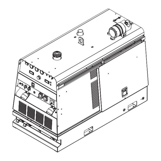
Page 21: Controls And Settings
OPERATION CONTROLS AND SETTINGS All welder and engine controls are located on the case front panel. Refer to Figure B.1 and the explanations that follow. FIGURE B.1 ENGINE CONTROLS (Items 1 through 9) 4. HOUR METER 1. RUN STOP SWITCH The hour meter displays the total time that the engine has been running. - Page 22 OPERATION Idler Operational exceptions 7. OIL PRESSURE GAUGE When the WELDING TERMINALS switch is in The gauge displays the engine oil pressure when the “Remotely Controlled” position the idler will the engine is running. operate as follows: a. When the triggering device (Amptrol, Arc Start 8.
-
Page 23: Auxiliary Power Controls
OPERATION 17. 6 - PIN CONNECTOR: 13. WELD MODE SELECTOR SWITCH: (Provides 3 selectable welding modes) For attaching optional remote control equipment. CV-WIRE When in the CC-STICK and CV-WIRE modes and when a remote control is connected to the CC-STICK Connector, the auto-sensing circuit automatically TOUCH START TIG switches the OUTPUT control from control at the welder to remote control. -
Page 24: Air Compressor Controls
OPERATION BATTERY JUMP START TERMINAL 23. GROUND STUD: (30-31) Provides a connection point for connecting the machine case to earth ground. Refer to “MACHINE GROUNDING” in the Installation 30. POSITIVE BATTERY JUMP START chapter for proper machine grounding informa- tion. TERMINAL. -
Page 25: What Are Vrd And Rocv Devices
OPERATION WHAT ARE VRD AND ROCV DEVICES? VRD/ROCVʼs are more commonly incorporated into the stick welding mode (CC) of the welding machines VRDʼs are gaining popularity as a “must have” safety being used in environments with high-risk of electric accessory especially where welding applications are shock. -
Page 26: Starting Technique
OPERATION TYPICAL FUEL CONSUMPTION Unlike other VRDʼs Lincoln uses micro processor con- trol to monitor and establish the arc without the stick- Refer to Table B.1 for typical fuel consumption of the ing and shorting of the electrode to the job as seen in AIR VANTAGE®... -
Page 27: Duty Cycle
OPERATION WELDER OPERATION The AIR VANTAGE® 500 (AU) is equipped with the required R.F. bypass circuitry for the connection of DUTY CYCLE high frequency generating equipment. Duty Cycle is the percentage of time the load is being The AIR VANTAGE® 500 (AU) and any high frequen- applied in a 10 minute period. -
Page 28: Wire Welding-Cv
OPERATION WIRE WELDING-CV ARC GOUGING For optimal performance when arc gouging, set the Connect a wire feeder to the AIR VANTAGE® 500 AIR VANTAGE® 500 (AU) “WELD MODE” switch to (AU) (AU)according to the instructions in INSTALLA- the “CC - STICK” position, and the “ARC CONTROL” TION INSTRUCTIONS Section. -
Page 29: Paralleling
B-10 B-10 OPERATION PARALLELING SIMULTANEOUS WELDING AND AUXIL- IARY POWER LOADS When paralleling machines in order to combine their It must be noted that the above auxiliary power ratings outputs, all units must be operated in the CC-STICK are with no welding load. mode only at the same output settings. -
Page 30: Accessories
The use of an arc welder for pipe thawing is not approved by the CSA, nor is it recommended or supported by Lincoln Electric. ------------------------------------------------------------------------ AIR VANTAGE® 500 (AU) -
Page 31: Maintenance
MAINTENANCE SAFETY PRECAUTIONS VMAC ™ WARNING (VEHICLE MOUNTED AIR COMPRESSORS) www.vmac.ca/index.php?airvantage500manuals • Have qualified personnel do all maintenance and troubleshooting work. 1333 Kipp Road • Turn the engine off before working inside the Nanamino machine or servicing the engine. British Columbia •... - Page 32 MAINTENANCE Service Instructions Service Instructions Single- and Two-Stage Engine Air Cleaners Single- and Two-Stage Engine Air Cleaners Inspect the New Filter for Damage Inspect the New Filter for Damage Remove the Filter Remove the Filter Inspect the new filter carefully, paying attention to Unfasten or unlatch the the inside of the open end, which is the service cover.
-
Page 33: Fuel Filters
MAINTENANCE FUEL FILTERS BATTERY HANDLING GASES FROM BATTERY can explode. WARNING • Keep sparks, flame and cigarettes away from battery. When working on the fuel system: • Keep naked lights away, do not smoke ! To prevent EXPLOSION when: • Do not spill fuel ! •... -
Page 34: Charging The Battery
MAINTENANCE WELDER / GENERATOR MAINTE- CHARGING THE BATTERY NANCE When you charge, jump, replace, or otherwise connect battery cables to the battery, be sure the polarity is STORAGE correct. Improper polarity can damage the charging circuit. The AIR VANTAGE® 500 (AU) positive (+) bat- Store the AIR VANTAGE®... -
Page 35: Troubleshooting
HOW TO USE TROUBLESHOOTING GUIDE WARNING Service and Repair should only be performed by Lincoln Electric Factory Trained Personnel. Unauthorized repairs performed on this equipment may result in danger to the technician and machine operator and will invalidate your factory warranty. For your safety and to avoid Electrical Shock, please observe all safety notes and precautions detailed throughout this manual. - Page 36 TROUBLESHOOTING Observe all Safety Guidelines detailed throughout this manual PROBLEMS POSSIBLE RECOMMENDED (SYMPTOMS) CAUSE COURSE OF ACTION Major Physical or Electrical Damage 1. Contact your local Lincoln is Evident. Authorized Field Service Facility. Engine will not crank 1. Battery low. 2.
- Page 37 TROUBLESHOOTING Observe all Safety Guidelines detailed throughout this manual PROBLEMS POSSIBLE RECOMMENDED (SYMPTOMS) CAUSE COURSE OF ACTION Battery does not stay charged. 1. Faulty battery . 2. Faulty engine alternator. 3. Loose or broken lead in charging circuit. 4. Loose fan belt may need tighten- ing.
- Page 38 TROUBLESHOOTING Observe all Safety Guidelines detailed throughout this manual PROBLEMS POSSIBLE RECOMMENDED (SYMPTOMS) CAUSE COURSE OF ACTION Engine goes to low idle but does not 1. Faulty Peripheral PCB, Pull stay at low idle. Coil/Battery PCB or Weld Control PCB. No welding output or auxiliary output.
- Page 39 ENHANCED DIAGRAM WIRING DIAGRAM AIR VANTAGE® 500 (AU)
- Page 40 DIAGRAMS AIR VANTAGE® 500 (AU)
- Page 41 DIAGRAMS AIR VANTAGE® 500 (AU)
- Page 42 DIAGRAMS AIR VANTAGE® 500 (AU)
- Page 43 DIAGRAMS AIR VANTAGE® 500 (AU)
- Page 44 DIAGRAMS AIR VANTAGE® 500 (AU)
- Page 45 DIAGRAMS AIR VANTAGE® 500 (AU)
- Page 46 DIAGRAMS AIR VANTAGE® 500 (AU)
- Page 47 DIAGRAMS AIR VANTAGE® 500 (AU)
- Page 48 F-10 F-10 DIAGRAMS AIR VANTAGE® 500 (AU)
- Page 49 F-11 F-11 DIAGRAMS AIR VANTAGE® 500 (AU)
- Page 50 F-12 F-12 DIAGRAMS AIR VANTAGE® 500 (AU)
- Page 51 F-13 F-13 DIAGRAMS AIR VANTAGE® 500 (AU)
- Page 52 F-14 F-14 DIMENSION PRINT AIR VANTAGE® 500 (AU)
- Page 53 NOTES AIR VANTAGE® 500 (AU)
- Page 54 D o not touch electrically live parts or K eep flammable materials away. W ear eye, ear and body protection. WARNING electrode with skin or wet clothing. Insulate yourself from work and ground. Spanish N o toque las partes o los electrodos M antenga el material combustible Protéjase los ojos, los oídos y el AVISO DE...
- Page 55 K eep your head out of fumes. T urn power off before servicing. D o not operate with panel open or WARNING U se ventilation or exhaust to guards off. remove fumes from breathing zone. Spanish L os humos fuera de la zona de res- D esconectar el cable de alimentación N o operar con panel abierto o AVISO DE...
- Page 56 Lincoln Electric for advice or information about their use of our products. We respond to our customers based on the best information in our possession at that time. Lincoln Electric is not in a position to warrant or guarantee such advice, and assumes no liability, with respect to such information or advice.