Advertisement
Quick Links
Operator's Manual
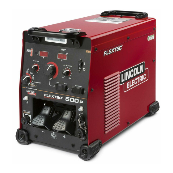
FLEXTEC
Register your machine:
www.lincolnelectric.com/register
Authorized Service and Distributor Locator:
www.lincolnelectric.com/locator
Save for future reference
Date Purchased
Code: (ex: 10859)
Serial: (ex: U1060512345)
IM10194-B
| Issue D ate Sep-16
© Lincoln Global, Inc. All Rights Reserved.
™
500 P
For use with machines having Code Numbers:
12246, 12565, 12607
Advertisement

Related Manuals for Lincoln Electric FLEXTEC 500 P


Summary of Contents for Lincoln Electric FLEXTEC 500 P
- Page 1 Operator’s Manual ™ FLEXTEC 500 P For use with machines having Code Numbers: 12246, 12565, 12607 Register your machine: www.lincolnelectric.com/register Authorized Service and Distributor Locator: www.lincolnelectric.com/locator Save for future reference Date Purchased Code: (ex: 10859) Serial: (ex: U1060512345) IM10194-B | Issue D ate Sep-16 ©...
- Page 2 THANK YOU FOR SELECTING A QUALITY PRODUCT BY KEEP YOUR HEAD OUT OF THE FUMES. DON’T get too close to the arc. LINCOLN ELEC TRIC. Use corrective lenses if necessary to stay a reasonable distance away from the arc. READ and obey the Safety Data PLEASE EXAMINE CARTON AND EQUIPMENT FOR Sheet (SDS) and the warning label DAMAGE IMMEDIATELY...
- Page 3 W117.2-1974. A Free copy of “Arc Welding Safety” booklet E205 is available from the Lincoln Electric Company, 2.d. All welders should use the following procedures in order to 22801 St. Clair Avenue, Cleveland, Ohio 44117-1199.
- Page 4 SAFETY ELECTRIC SHOCK ARC RAYS CAN BURN. CAN KILL. 3.a. The electrode and work (or ground) circuits are 4.a. Use a shield with the proper filter and cover plates to protect your electrically “hot” when the welder is on. Do eyes from sparks and the rays of the arc when welding or not touch these “hot”...
- Page 5 SAFETY WELDING AND CUTTING CYLINDER MAY EXPLODE IF SPARKS CAN CAUSE DAMAGED. FIRE OR EXPLOSION. 7.a. Use only compressed gas cylinders containing the correct shielding gas for the process used 6.a. Remove fire hazards from the welding area. If and properly operating regulators designed for this is not possible, cover them to prevent the welding sparks the gas and pressure used.
- Page 6 FLEXTEC™ 500 P TABLE OF CONTENTS...
- Page 7 FLEXTEC™ 500 P TABLE OF CONTENTS...
- Page 8 FLEXTEC™ 500 P CHANGES AFTER INITIAL RELEASE CHANGES AFTER INITIAL RELEASE...
- Page 9 PRODUCT DESCRIPTION PRODUCT DESCRIPTION Product Summary The Flextec™ 500 P is a multi-process CC/CV/Pulse DC inverter power source rated for 450 Amps, 38 Volts at 100% duty cycle. The Flextec™ 500 P comes in a rugged case and is intended for either indoor or outdoor operation and comes with an IP23 environmental rating.
- Page 10 NR-203; NR-211, STEEL NR-440NI2 PROCESS LIMITATIONS The Flextec 500 P is suitable only for the processes listed. EQUIPMENT LIMITATIONS Operating Temperature Range is -10° C to + 55° C. Output is de-rated for temperatures in excess of 40° C. OUTPUT RATINGS AT 40° C...
- Page 11 FLEXTEC™ 500 P PRODUCT DESCRIPTION COMMON OPTIONAL KITS & ACCESSORIES K3059-2 INVERTER CART K3056-1 BASE MOUNTING KIT K3091-1 MULTI-PROCESS SWITCH K2909-1 12-PIN TO 6-PIN ADAPTER K3127-1 WIRELESS FOOT PEDAL K857-2 REMOTE OUTPUT CONTROL WITH 12-PIN UNIVERSAL CONNECTOR (25 FEET) K870-2 FOOT AMPTROL K963-3 HAND AMPTROL...
- Page 12 FLEXTEC™ 500 P NOTES...
- Page 13 FLEXTEC™ 500 P DESIGN DESIGN TECHNICAL SPECIFICATIONS POWER SOURCES - INPUT VOLTAGE AND CURRENT MODEL DUTY CYCLE INPUT VOLTAGE ± 10% INPUT AMPERES IDLE POWER (W) POWER FACTOR K4092-1 60% RATING 380 / 460 / 575 / 3 / 50 / 60 39 / 32 / 32 150W FAN ON 100% RATING...
- Page 14 FLEXTEC™ 500 P DESIGN AGENCY APPROVALS MODEL MARKET CONFORMITY MARK NOTES K4092-1 US AND CANADA C/US REQUIRES K3129-2 AUSTRALIA C-TICK / RCM EUROPE CE FILTER KIT DESIGN FEATURES • Pulse Modes – for demanding applications that require low heat • The Future is Now – You no longer have to pay a price premium input and reduced spatter to gain the advantages of inverter technology over conventional welders.
- Page 15 FLEXTEC™ 500 P DESIGN CASE FRONT CONTROLS 8. Local/Remote Selector Toggle Switch: CASE FRONT CONTROLS DESCRIPTIONS. Sets the control of the output to local (output control knob) or remote (K857 hand amptrol or K870 foot amptrol through the 12- pin or 14-pin circular connectors). 1.
- Page 16 FLEXTEC™ 500 P DESIGN CASE BACK CONTROLS CASE BACK CONTROLS DESCRIPTIONS. 1. Input Power Cord Access Hole 2. Access Panel – Allows access for connecting input power and configuring the machine 3. Input Power Reconnect – Configures the machine for the input supply voltage 4.
- Page 17 FLEXTEC™ 500 P DESIGN INTERNAL CONTROLS Internal Controls Description The User Interface pc board has one bank of dip switches (See Figure A.1). As shipped from the factory and under normal conditions, the dip switches are all in the ‘off’ position (Figure A.2). There are 2 instances that require a change of the dip switch.
- Page 18 FLEXTEC™ 500 P INSTALLATION INSTALLATION WARNING ELECTRIC SHOCK CAN KILL. ONLY QUALIFIED PERSONNEL SHOULD PERFORM THIS INSTALLATION. • TURN OFF INPUT POWER TO THE POWER SOURCE AT THE DISCONNECT SWITCH OR FUSE BOX BEFORE WORKING ON THIS EQUIPMENT. TURN OFF THE INPUT POWER TO ANY OTHER EQUIPMENT CONNECTED TO THE WELDING SYSTEM AT THE DISCONNECT SWITCH OR FUSE BOX BEFORE...
- Page 19 FLEXTEC™ 500 P INSTALLATION Use a three-phase supply line. A 1.75 inch (45 mm) diameter access hole for the input supply is located on the case back. Remove the reconnect access panel located on the case back and connect L1, L2, L3 and ground according to the Input Supply Connection Diagram decal.
- Page 20 FLEXTEC™ 500 P INSTALLATION INPUT VOLTAGE SELECTION HIGH FREQUENCY PROTECTION Locate the Flextec™ 500 P away from radio controlled machinery. The normal operation of the machine may adversely affect the Welders are shipped connected for 460V input voltage. If the operation of RF controlled equipment, which may result in bodily Auxiliary lead (indicated as ‘A’) is placed in the wrong position and injury or damage to the equipment.
- Page 21 FLEXTEC™ 500 P INSTALLATION CONNECTION DIAGRAMS, CONTROL CABLES Analog Wire Feeder Connectivity Picture Function Wiring 14-pin Ground connector for Trigger, Common wire feeder Trigger input connectivity. 77 Remote potentiometer, 10V 76 Remote potentiometer, wiper 75 Remote potentiometer, common Work (21) 42 VAC 42 VAC...
- Page 22 FLEXTEC™ 500 P INSTALLATION ArcLink Wire Feeder & Digital Accessory Connectivity Picture Function Wiring ArcLink CAN 5-pin ArcLink CAN connector for Electrode Sense Lead wire feeder 40Vdc connectivity. 40Vdc Common Picture Function Wiring ArcLink CAN ArcLink CAN Remote Potentiometer Common 12-pin remote Remote Potentiometer Wiper control...
- Page 23 FLEXTEC™ 500 P INSTALLATION • Route all cables directly to the work and wire feeder, avoid RECOMMENDED ELECTRODE AND WORK excessive lengths and do not coil excess cable. Route the CABLE SIZES FOR ARC WELDING electrode and work cables in close proximity to one another to General Guidelines minimize the loop area and therefore the inductance of the weld circuit.
- Page 24 FLEXTEC™ 500 P INSTALLATION CONTROL CABLE AND VOLTAGE SENSING CONNECTIONS Electrode Voltage Sensing General Guidelines The remote ELECTRODE sense lead (67) is built into the 5-pin ArcLink Genuine Lincoln control cables should be used at all times (except control cable (K1543-xx) and is always connected to the wire drive where noted otherwise).
- Page 25 Figure B2, and set the output control of each power sources to one half of the desired arc current. Figure B.2 INPUT LINES INPUT TERMINAL BLOCK TO GROUND PER NATIONAL FLEXTEC 500 P ELECTRICAL CODE (MACHINE #1) NEGATIVE POSITIVE INPUT LINES INPUT TERMINAL BLOCK...
- Page 26 FLEXTEC™ 500 P OPERATION OPERATION GRAPHIC SYMBOLS THAT APPEAR ON THIS MACHINE OR IN THIS MANUAL RATED REDUCED INPUT POWER NO-LOAD VOLTAGE OPEN CIRCUIT VOLTAGE INPUT VOLTAGE OUTPUT VOLTAGE HIGH TEMPERATURE INPUT CURRENT MACHINE STATUS CIRCUIT BREAKER OUTPUT CURRENT PROTECTIVE WIRE FEEDER GROUND POSITIVE OUTPUT...
- Page 27 FLEXTEC™ 500 P OPERATION POWER-UP SEQUENCE WARNING ELECTRIC SHOCK can kill. UNLESS USING COLD FEED FEATURE, WHEN FEEDING WITH GUN TRIGGER, THE ELEC- TRODE AND DRIVE MECHANISM ARE ALWAYS ELECTRICALLY ENERGIZED AND COULD REMAIN ENERGIZED SEVERAL SECONDS AFTER THE WELDING CEASES. -------------------------------------------------------- FUMES AND GASES can be dangerous to your health.
- Page 28 FLEXTEC™ 500 P OPERATION DUTY CYCLE DEFINITION OF WELDING MODES NON-SYNERGIC WELDING MODES The Flextec™ 500 P is capable of welding at a 100% duty cycle (continuous welding) at 450 Amps rated output. • A Non-synergic welding mode requires all welding process The 60% duty cycle rating is 500 amps (based off of a ten minute variables to be set by the operator.
- Page 29 FLEXTEC™ 500 P OPERATION Output Control Dial Control - Local/Remote Toggle Switch Output control is conducted via a single turn potentiometer. • Set the switch to ‘local’ to control output at the Flextec™ via the Adjustment is indicated by the meters. Output Control dial.
- Page 30 FLEXTEC™ 500 P OPERATION • When the Local/Remote is set to Remote, this dial sets the BASIC MODES OF OPERATION maximum welding amperage. The remote potentiometer than controls the amperage from minimum to this pre-set maximum. SMAW This weld mode is a constant current (CC) mode featuring continuous control from 15 –...
- Page 31 FLEXTEC™ 500 P OPERATION GTAW This weld mode is a constant current (CC) mode featuring continuous control from 10 –500 amps. It is intended for the GTAW TIG welding processes. Hot Start - Hot start regulates the arc initiation current. A setting of +10 results in the most positive arc initiation.
- Page 32 FLEXTEC™ 500 P OPERATION CV-GAS This weld mode is a constant voltage (CV) mode featuring continuous control from 10 to 45 volts. It is intended for the GMAW, FCAW-GS, MCAW welding processes and arc gouging. Hot Start – Rotate from the ‘0’ position to the ‘10’ position to provide more energy during the start of a weld.
- Page 33 FLEXTEC™ 500 P OPERATION CV-INNERSHIELD This weld mode is a constant voltage (CV) mode featuring continuous control from 10 to 45 volts. It is intended for the FCAW-SS welding process and arc gouging. Hot Start – Toggle from the ‘0’ position to the ‘10’ position to provide more energy during the start of a weld.
- Page 34 FLEXTEC™ 500 P OPERATION ARCLINK This weld mode is intended to unlock basic non-synergic, synergic and pulse modes intended for use with a compatible ArcLink wire feeders. All of the Flextec™ 500 P user interface controls are disabled in this mode and controlling the power source is accomplished from the wire feeder user interface.
- Page 35 FLEXTEC™ 500 P OPERATION PULSE WELDING IN ARCLINK MODE Pulse welding procedures are set by controlling an overall “arc length” variable. When pulse welding, the arc voltage is highly dependent upon the waveform. The peak current, back ground current, rise time, fall time and pulse frequency all affect the voltage. The exact voltage for a given wire feed speed can only be predicted when all the pulsing waveform parameters are known.
- Page 36 For additional information about UltimArc Arc Controls and pulse welding procedure Lincoln Electric publishes process documents as informational guides on various welding procedures. Access to the process documents can be attained at the following web address: http://www.lincolnelectric.com/en-us/equipment/advanced-process-...
- Page 37 DC welding power source and the work clamp. Weld Fume Control Solutions. Lincoln Electric offers a wide variety of welding fume control solutions, ranging from portable systems easily wheeled around the shop to shop-wide central systems servicing many dedicated welding stations.
- Page 38 FLEXTEC™ 500 P MAINTENANCE MAINTENANCE PERIODIC MAINTENANCE WARNING Thermal Protection Thermostats protect the machine from excessive operating temperatures. Excessive temperatures may be caused by a lack of ELECTRIC SHOCK can kill. cooling air or operating the machine beyond the duty cycle and output •...
- Page 39 HOW TO USE TROUBLESHOOTING GUIDE WARNING Service and Repair should only be performed by Lincoln Electric Factory Trained Personnel. Unauthorized repairs performed on this equipment may result in danger to the technician and machine operator and will invalidate your factory warranty.
- Page 40 FLEXTEC™ 500 P TROUBLE SHOOTING ERROR CODES The status lights on the User Interface board and the Switch board are Errors are displayed on the user interface. In addition, there are status dual-color LED’s. Normal operation for each is steady green. lights on the User Interface PC board and the Switch PC board that contain error sequences.
- Page 41 COURSE OF ACTION Major physical or electrical damage 1. Contact your local authorized is evident when the sheet metal Lincoln Electric Field Service facility covers are removed. for technical assistance. Machine won’t weld, can’t get any 1. If the displays show an Err ### output.
- Page 42 FLEXTEC™ 500 P DIAGRAMS FRONT OF MACHINE ~575V ~42V ~460V ~380V ~52V ~115V H3...
- Page 43 FLEXTEC™ 500 P DIAGRAMS...
- Page 44 FLEXTEC™ 500 P DIAGRAMS...
- Page 45 FLEXTEC™ 500 P DIAGRAMS...
- Page 46 FLEXTEC™ 500 P DIAGRAMS...
- Page 47 FLEXTEC™ 500 P DIAGRAMS...
- Page 48 FLEXTEC™ 500 P DIAGRAMS...
- Page 49 Flextec 500P - 12607...
- Page 50 THIS PAGE INTENTIONALLY LEFT BLANK...
- Page 51 Index of Sub Assemblies - 12607 PART NUMBER DESCRIPTION P-1068-A INDEX OF SUB ASSEMBLIES P-1068-C CASE FRONT ASSEMBLY P-1068-D DIVIDER PANEL ASSEMBLY P-1068-E BASE & CENTER ASSEMBLY P-1068-F CASE BACK ASSEMBLY P-1068-G WRAPAROUND ASSEMBLY Flextec 500P - 12607...
- Page 52 Index of Sub Assemblies - 12607 P-1068-A.jpg Flextec 500P - 12607...
- Page 53 Case Front Assembly PART NUMBER DESCRIPTION 9SG7794-10 CASE FRONT ASSEMBLY 9SG7793-5 CASE FRONT 9SG7807 NAMEPLATE 9SS16656-4 OUTPUT TERMINAL ASBLY 9SCF000371 #10-24X.50HHCS-FULL-GR2-3147 9SG6864-1 NEGATIVE OUTPUT STUD COVER 9SS9225-100 SELF TAPPING SCREW 9SS9262-184 WASHER 9SG6864-2 POSITIVE OUTPUT STUD COVER 9SS9225-100 SELF TAPPING SCREW 9SS9262-184 WASHER 9ST12287-20...
- Page 54 Case Front Assembly PART NUMBER DESCRIPTION 9SCF000002 #4-40HN 9SCF000010 #10-24HN 9SE106A-1 LOCKWASHER 9SS26124 GROUND REFERENCE 9SS28393-3 OUTPUT SNUBBER ASBLY 9SS18858-5 SUPPRESSOR ASBLY 9SS9262-1 PLAIN WASHER 9SE106A-15 LOCKWASHER 9SCF000344 HEX HD SCREW 9SS30151 POSITIVE OUTPUT STUD LEAD 9SM22778-1 KNOB 1.0" 9SM22778-2 KNOB 1.5"...
- Page 55 Case Front Assembly P-1068-C.jpg Flextec 500P - 12607...
- Page 56 Divider Panel Assembly PART NUMBER DESCRIPTION 9SG7810-2 DIVIDER PANEL ASSEMBLY 9SG7808 DIVIDER PANEL 9SM22062-2 INPUT RECTIFIER ASSEMBLY 9SM15454-18 INPUT RECTIFIER MODULE 9SS24574-1 INPUT HEATSINK 9SS9262-98 PLAIN WASHER 9SE106A-2 LOCKWASHER 9SCF000013 1/4-20X.625HHCS 9SM25066 AIR DEFLECTER 9SS9225-68 THREAD FORMING SCREW (CUTTING) 9SS28841 GROUND LUG 9SS9225-45 THREAD FORMING SCREW...
- Page 57 Divider Panel Assembly PART NUMBER DESCRIPTION 9SL16423-1 40 V BUS PC BD ASBLY 9ST9187-13 #10-24HLN-1817/1-NYLON INSERT 9ST11267-A INSULATOR 9ST11267-B INSULATOR 9ST10728-77 FUSE 9SS18491-1 MOV ASBLY 9SS18250-1074 PLUG & LEAD ASBLY 9SL16767 AUX TRANSFORMER THERMOSTAT ASBLY 9SS13000-129 AUXILIARY TRANSFORMER 9ST13359-15 THERMOSTAT 9SS9225-32 THREAD FORMING SCREWS 9SS9262-98...
- Page 58 Divider Panel Assembly P-1068-D.jpg Flextec 500P - 12607...
- Page 59 Base & Center Assembly PART NUMBER DESCRIPTION 9SG7797-10 BASE & CENTER ASSEMBLY 9SG7791 BASE 9SL13138 CORNER CAP 9SS9262-183 PLAIN WASHER 9SS9225-66 SELF TAPPING SCREW 9ST11267-A INSULATOR 9SS10404-127 RESISTORWW100W1005% 9SCF000191 #10-24X7.50RHS 9SS9262-27 PLAIN WASHER 9SE106A-1 LOCKWASHER 9SCF000010 #10-24HN 9SL16500 CHOKE ASBLY 9SS9225-66 SELF TAPPING SCREW 9SS9262-98...
- Page 60 Base & Center Assembly PART NUMBER DESCRIPTION 9SE106A-3 LOCKWASHER 9SCF000029 5/16-18HN 9SCF000040 5/16-18X.75HHCS 9SS9262-30 PLAIN WASHER 9SE106A-3 LOCKWASHER 9SCF000028 5/16-18X1.25HHCS 9SS9262-30 PLAIN WASHER 9SE106A-3 LOCKWASHER 9SCF000029 5/16-18HN 9SCF000040 5/16-18X.75HHCS 9SS9262-30 PLAIN WASHER 9SE106A-3 LOCKWASHER 9SG8122 SWITCHBOARD ASBLY 9SS9225-66 SELF TAPPING SCREW 9SCF000013 1/4-20X.625HHCS 9SS9262-98...
- Page 61 Base & Center Assembly P-1068-E.jpg Flextec 500P - 12607...
- Page 62 Case Back Assembly PART NUMBER DESCRIPTION 9SG7796 CASE BACK ASSEMBLY 9SG7795 CASE BACK 9SM25055 9SS9225-68 THREAD FORMING SCREW (CUTTING) 9SM24995 REAR HANDLE SUPPORT BRACKET 9SG6525-3 HANDLE 9SS9225-66 SELF TAPPING SCREW 9SS18250-1062 PLUG & LEAD ASBLY 9SS30907 RELAY SUPPORT 9SS9262-3 PLAIN WASHER 9ST4291-A LOCKWASHER 9SCF000042...
- Page 63 Case Back Assembly P-1068-F.jpg Flextec 500P - 12607...
- Page 64 Wraparound Assembly PART NUMBER DESCRIPTION 9SG7801 LEFT CASE SIDE 9ST10097-5 SPEED GRIP NUT RETAINER 9SS9225-66 SELF TAPPING SCREW 9SS9225-68 THREAD FORMING SCREW (CUTTING) 9SS9262-183 PLAIN WASHER 9SG7802 RIGHT CASE SIDE 9ST10097-5 SPEED GRIP NUT RETAINER 9SS9225-66 SELF TAPPING SCREW 9SS9225-68 THREAD FORMING SCREW (CUTTING) 9SS9262-183 PLAIN WASHER...
- Page 65 Wraparound Assembly P-1068-G.jpg Flextec 500P - 12607...
- Page 66 WARNING Do not touch electrically live parts or Keep flammable materials away. Wear eye, ear and body protection. electrode with skin or wet clothing. Insulate yourself from work and AVISO DE ground. Spanish PRECAUCION No toque las partes o los electrodos Mantenga el material combustible Protéjase los ojos, los oídos y el bajo carga con la piel o ropa moja-...
- Page 67 WARNING Keep your head out of fumes. Turn power off before servicing. Do not operate with panel open or Use ventilation or exhaust to guards off. remove fumes from breathing zone. AVISO DE Spanish PRECAUCION Los humos fuera de la zona de res- Desconectar el cable de ali- No operar con panel abierto o piración.
- Page 68 Lincoln Electric for advice or information about their use of our products. We respond to our customers based on the best information in our possession at that time. Lincoln Electric is not in a position to warrant or guarantee such advice, and assumes no liability, with respect to such information or advice.