Table of Contents
Advertisement
Quick Links
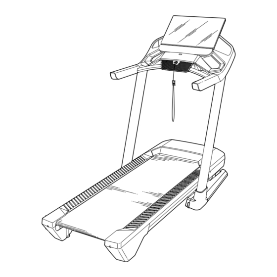
Model No. PFTL15820-INT.2
Serial No.
Write the serial number in the space
above for reference.
Serial
Number
Decal
CUSTOMER SERVICE
UNITED KINGDOM
Call: 08457 089 009
From Ireland: 053 92 36102
Website: www.iconsupport.eu
E-mail: csuk@iconeurope.com
Write:
ICON Health & Fitness, Ltd.
Unit 4, Westgate Court
Silkwood Park
OSSETT
WF5 9TT
UNITED KINGDOM
AUSTRALIA
Call: 1800 993 770
E-mail: australiacc@iconfitness.com
Write:
ICON Health & Fitness
PO Box 635
WINSTON HILLS NSW 2153
AUSTRALIA
CAUTION
Read all precautions and
instructions in this manual before
using this equipment. Save this
manual for future reference.
USER'S MANUAL
iconeurope.com
Advertisement
Table of Contents

Related Manuals for Pro-Form PFTL15820-INT.2


Summary of Contents for Pro-Form PFTL15820-INT.2
- Page 1 Model No. PFTL15820-INT.2 Serial No. USER’S MANUAL Write the serial number in the space above for reference. Serial Number Decal CUSTOMER SERVICE UNITED KINGDOM Call: 08457 089 009 From Ireland: 053 92 36102 Website: www.iconsupport.eu E-mail: csuk@iconeurope.com Write: ICON Health & Fitness, Ltd.
-
Page 2: Table Of Contents
TABLE OF CONTENTS WARNING DECAL PLACEMENT ............. . .2 IMPORTANT PRECAUTIONS . -
Page 3: Important Precautions
IMPORTANT PRECAUTIONS WARNING: To reduce the risk of burns, fire, electric shock, or injury to persons, read all important precautions and instructions in this manual and all warnings on your treadmill before using your treadmill. ICON assumes no responsibility for personal injury or property damage sus- tained by or through the use of this product. - Page 4 21. The treadmill is capable of high speeds. 27. Inspect and properly tighten all parts each Adjust the speed in small increments to time the treadmill is used. avoid sudden jumps in speed. DANGER: Always unplug the power 22. Never leave the treadmill unattended while cord immediately after use, before clean- it is running.
-
Page 5: Before You Begin
BEFORE YOU BEGIN Thank you for selecting the revolutionary PROFORM reading this manual, please see the front cover of this ® PRO 9000 treadmill. The PRO 9000 treadmill offers an manual. To help us assist you, please note the product impressive selection of features designed to make your model number and serial number before contacting us. -
Page 6: Part Identification Chart
PART IDENTIFICATION CHART Use the drawings below to identify small parts used for assembly. The number in parentheses below each draw- ing is the key number of the part, from the PART LIST near the end of this manual. The number following the key number is the quantity used for assembly. -
Page 7: Assembly
ASSEMBLY • Assembly requires two persons. • Left parts are marked “L” or “Left” and right parts are marked “R” or “Right.” • Place all parts in a cleared area and remove the packing materials. Do not dispose of the packing •... - Page 8 2. Make sure that the power cord is unplugged. Locate the Upright Wire (90) attached to the Base (96) with a tie. Remove the tie. Next, identify the Right Upright (92). Have a second person hold the Right Upright near the Base (96).
- Page 9 4. Identify the Left and Right Base Covers (97, 98). Slide the Left Base Cover onto the Left Upright (91), and slide the Right Base Cover onto the Right Upright (92). Then, slide the Base Covers all of the way down to the floor. 5.
- Page 10 6. Set the console assembly (C) face down on a soft surface to avoid scratching the console assembly. Remove and save the four 1/4" x 1/2" Screws (20). Next, identify the Left and Right Trays (104, 105). Attach the Trays to the console assembly (C) with eight #8 x 3/8"...
- Page 11 8. With the help of a second person, hold the con- sole assembly (C) near the Right Handrail (84). Connect the Upright Wire (90) to the con- sole wire (D). The connectors should slide together easily and snap into place. If they do not, turn one connector and try again.
- Page 12 10. Start two #8 x 1/2" Screws (2) into the Crossbar (89), and then tighten them; do not overtighten the Screws. 11. Align the Right Top Handrail Cover (82) with the Crossbar (89) and with the holes (F) in the Right Handrail (84).
- Page 13 12. Note: If the treadmill is assembled on a smooth surface, it may roll forward in this step. Remove the two 5/16" x 3/4" Screws (21) from the Latch Crossbar (59). Next, raise the Frame (64) to the upright posi- tion.
- Page 14 14. Remove the 5/16" Nut (39) and the 5/16" x 2 1/4" Bolt (28) from the bracket on the Latch Crossbar (59). Align the upper end of the Storage Latch (63) with the bracket on the Latch Crossbar (59), and insert the 5/16"...
- Page 15 16. Firmly tighten the four 3/8" x 2 3/8" Screws (3) and the two 3/8" x 1 1/4" Screws (1). Next, tighten the two 3/8" x 1 3/4" Screws (4); make sure that the Wheels (93) turn freely. Then, set the Right Inner Base Cover (100) onto the lower end of the Right Upright (92) and Base (96).
-
Page 16: How To Use The Treadmill
HOW TO USE THE TREADMILL HOW TO PLUG IN THE POWER CORD Follow the steps below to plug in the power cord. This product must be earthed. If it should malfunc- 1. Plug the tion or break down, earthing provides a path of least indicated resistance for electric current to reduce the risk of end of the... - Page 17 CONSOLE DIAGRAM FEATURES OF THE CONSOLE exercise feedback. You can even measure your heart rate using a compatible heart rate monitor. See page The advanced treadmill console offers a selection of 26 for information about purchasing an optional heart rate monitor. features designed to make your workouts more effec- tive and enjoyable.
- Page 18 HOW TO TURN ON THE POWER HOW TO USE THE TOUCH SCREEN IMPORTANT: If the treadmill has been exposed to The console features a tablet with a full-color touch cold temperatures, allow it to warm to room tem- screen. The following information will help you become perature before you turn on the power.
- Page 19 HOW TO SET UP THE CONSOLE 5. Check for firmware updates. Before using the treadmill for the first time, set up the First, touch your name or Hello on the screen, and then touch Settings. Next, select the maintenance console. section.
- Page 20 HOW TO USE THE MANUAL MODE 4. Change the incline of the treadmill as desired. 1. Insert the key into the console. To change the incline of the treadmill, press the Incline increase and decrease buttons or one of the See HOW TO TURN ON THE POWER on numbered incline buttons.
- Page 21 6. Turn on the fan if desired. 3. Select a map workout. The fan features several To select a map workout, touch the desired option speed settings. Press the on the screen. Note: The featured map workouts fan buttons repeatedly to on your console will change periodically.
- Page 22 HOW TO USE A DRAW YOUR OWN MAP 4. Save your workout. WORKOUT Touch Save New Workout on the screen. If desired, Note: To use a draw your own map workout, the change the title of the workout or add a description, console must be connected to a wireless network (see and then press the >...
- Page 23 HOW TO USE A DISTANCE OR TIME WORKOUT 5. Select a distance or time workout that you have previously added to your schedule on iFit.com. Note: To use a distance or time workout, the console must be connected to a wireless network (see HOW Touch the calendar icon to download a distance or TO CONNECT TO A WIRELESS NETWORK on page time workout from your schedule.
- Page 24 HOW TO CHANGE CONSOLE SETTINGS 4. View machine information. IMPORTANT: Some of the settings and features Touch Equipment Info, and then touch Machine described may not be enabled. Occasionally, a Info to view information about your treadmill. firmware update may cause your console to function slightly differently.
- Page 25 HOW TO CONNECT TO A WIRELESS NETWORK An information box will ask if you want to connect to the wireless network. Touch Connect to connect The console is Wi-Fi enabled, allowing you to set up a to the network or touch Cancel to return to the list wireless network connection.
- Page 26 HOW TO USE THE SOUND SYSTEM THE OPTIONAL HEART RATE MONITOR To play music or audio books through the console Whether your sound system while you exercise, you can connect goal is to your Bluetooth-enabled device to the console. burn fat or to strengthen your You can then adjust the volume cardiovascular...
-
Page 27: How To Fold And Move The Treadmill
HOW TO FOLD AND MOVE THE TREADMILL HOW TO FOLD THE TREADMILL HOW TO MOVE THE TREADMILL To avoid damaging the treadmill, adjust the incline Before moving the treadmill, fold it as described at the to zero before you fold the treadmill. Then, remove left. -
Page 28: Maintenance And Troubleshooting
MAINTENANCE AND TROUBLESHOOTING MAINTENANCE c. Check the power switch located on the treadmill frame near the power cord. If the switch protrudes Regular maintenance is important for optimal perfor- as shown (A), the switch has tripped. To reset the mance and to reduce wear. Inspect and properly tighten power switch, wait for five minutes and then press all parts each time the treadmill is used. - Page 29 SYMPTOM: The walking belt slows when walked on SYMPTOM: The walking belt is not centered between the foot rails a. Use only a surge suppressor that meets all of the IMPORTANT: If the walking belt rubs against specifications described on page 16. the foot rails (D), the walking belt may become b.
- Page 30 SYMPTOM: The displays of the console do not b. If the console does not boot up properly, or function properly if the console freezes and does not respond, reset the console to the factory default settings. IMPORTANT: Doing this will erase all the a.
-
Page 31: Exercise Guidelines
EXERCISE GUIDELINES Aerobic Exercise—If your goal is to strengthen your WARNING: cardiovascular system, you must perform aerobic Before beginning this exercise, which is activity that requires large amounts or any exercise program, consult your physi- of oxygen for prolonged periods of time. For aerobic cian. - Page 32 SUGGESTED STRETCHES The correct form for several basic stretches is shown at the right. Move slowly as you stretch —never bounce. 1. Toe Touch Stretch Stand with your knees bent slightly and slowly bend forward from your hips. Allow your back and shoulders to relax as you reach down toward your toes as far as possible.
- Page 33 NOTES...
-
Page 34: Part List
PART LIST Model No. PFTL15820-INT.2 R0321A Key No. Qty. Description Key No. Qty. Description 3/8" x 1 1/4" Screw Belt Guide #8 x 1/2" Screw Left Frame Cover 3/8" x 2 3/8" Screw Right Frame Cover 3/8" x 1 3/4" Screw Drive Roller/Pulley #8 x 3/4"... - Page 35 Key No. Qty. Description Key No. Qty. Description Grommet Large Plastic Bushing Console Console Pivot Plate Console Base Wire Cover Left Tray Quick Control Console Right Tray Console Frame Plate Fan Screw Console Cover #8 x 3/4" Tek Screw Console Frame Cap Reed Switch Console Frame Clamp...
-
Page 36: Exploded Drawing
EXPLODED DRAWING A Model No. PFTL15820-INT.2 R0321A... - Page 37 EXPLODED DRAWING B Model No. PFTL15820-INT.2 R0321A...
- Page 38 EXPLODED DRAWING C Model No. PFTL15820-INT.2 R0321A...
- Page 39 EXPLODED DRAWING D Model No. PFTL15820-INT.2 R0321A...
-
Page 40: Ordering Replacement Parts
ORDERING REPLACEMENT PARTS To order replacement parts, please see the front cover of this manual. To help us assist you, be prepared to provide the following information when contacting us: • the model number and serial number of the product (see the front cover of this manual) •...