Pro-Form PRO 9000 User Manual
Hide thumbs
Also See for PRO 9000:
- User manual (40 pages) ,
- User manual (40 pages) ,
- User manual (40 pages)
Advertisement
Table of Contents
- 1 Table of Contents
- 2 Warning Decal Placement
- 3 Important Precautions
- 4 Before You Begin
- 5 Part Identification Chart
- 6 Assembly
- 7 How to Use the Treadmill
- 8 Fcc Information
- 9 How to Fold and Move the Treadmill
- 10 Maintenance and Troubleshooting
- 11 Exercise Guidelines
- 12 Part List
- 13 Exploded Drawing
- 14 Ordering Replacement Parts
- 15 Limited Warranty
- Download this manual
proform.com
Model No. PFTL15820.0
Serial No.
Write the serial number in the space
above for reference.
Serial
Number
Decal
REGISTER YOUR
PRODUCT
To register your product and
activate your warranty today,
go to my.proform.com.
CUSTOMER CARE
For service at any time, go to
support.proform.com.
Or call 1-888-533-1333
Mon.–Fri. 6 a.m.–6 p.m. MT
Sat. 8 a.m.–12 p.m. MT
Please do not contact the store.
CAUTION
Read all precautions and
instructions in this manual before
using this equipment. Save this
manual for future reference.
USER'S MANUAL
Advertisement
Table of Contents

Related Manuals for Pro-Form PRO 9000


Summary of Contents for Pro-Form PRO 9000
- Page 1 proform.com USER’S MANUAL Model No. PFTL15820.0 Serial No. Write the serial number in the space above for reference. Serial Number Decal REGISTER YOUR PRODUCT To register your product and activate your warranty today, go to my.proform.com. CUSTOMER CARE For service at any time, go to support.proform.com.
-
Page 2: Table Of Contents
TABLE OF CONTENTS WARNING DECAL PLACEMENT ............. . .2 IMPORTANT PRECAUTIONS . -
Page 3: Important Precautions
IMPORTANT PRECAUTIONS WARNING: To reduce the risk of burns, fire, electric shock, or injury to persons, read all important precautions and instructions in this manual and all warnings on your treadmill before using your treadmill. ICON assumes no responsibility for personal injury or property damage sus- tained by or through the use of this product. - Page 4 19. Always stand on the foot rails when starting 26. Do not change the incline of the treadmill by or stopping the walking belt. Always hold the placing objects under the treadmill. handrails while using the treadmill. 27. Never insert any object into any opening on 20.
- Page 5 STANDARD SERVICE PLANS...
-
Page 6: Before You Begin
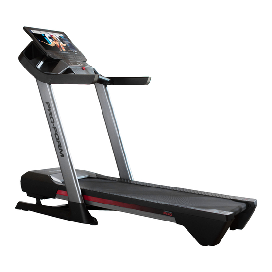
Thank you for selecting the revolutionary PROFORM reading this manual, please see the front cover of this ® PRO 9000 treadmill. The PRO 9000 treadmill offers an manual. To help us assist you, please note the product impressive selection of features designed to make your model number and serial number before contacting us. -
Page 7: Part Identification Chart
PART IDENTIFICATION CHART Use the drawings below to identify small parts used for assembly. The number in parentheses below each draw- ing is the key number of the part, from the PART LIST near the end of this manual. The number following the key number is the quantity used for assembly. -
Page 8: Assembly
ASSEMBLY 1. To use the assembly steps in this manual, first see the helpful tips below. • To hire an authorized service technician to • To identify small parts, see page 7. assemble the treadmill, call 1-800-445-2480. • Left parts are marked “L” or “Left” and right parts •... - Page 9 2. Make sure that the power cord is unplugged. Locate the Upright Wire (90) attached to the Base (96) with a tie. Remove the tie. Next, identify the Right Upright (92). Have a second person hold the Right Upright near the Base (96).
- Page 10 4. Identify the Left and Right Base Covers (97, 98). Slide the Left Base Cover onto the Left Upright (91), and slide the Right Base Cover onto the Right Upright (92). Then, slide the Base Covers all the way down to the floor. 5.
- Page 11 6. Set the console assembly (C) face down on a soft surface to avoid scratching the console assembly. Remove and save the four 1/4" x 1/2" Screws (20). Next, identify the Left and Right Trays (104, 105). Attach the Trays to the console assembly (C) with eight #8 x 3/8"...
- Page 12 8. With the help of a second person, hold the con- sole assembly (C) near the Right Handrail (84). Connect the Upright Wire (90) to the con- sole wire (D). The connectors should slide together easily and snap into place. If they do not, turn one connector and try again.
- Page 13 10. Start two #8 x 1/2" Screws (2) into the Crossbar (89), and then tighten them; do not overtighten the Screws. 11. Align the Right Top Handrail Cover (82) with the Crossbar (89) and with the holes (F) in the Right Handrail (84).
- Page 14 12. Note: If the treadmill is assembled on a smooth surface, it may roll forward in this step. Remove the two 5/16" x 3/4" Screws (21) from the Latch Crossbar (59). Next, raise the Frame (64) to the upright posi- tion.
- Page 15 14. Remove the 5/16" Nut (39) and the 5/16" x 2 1/4" Bolt (28) from the bracket on the Latch Crossbar (59). Align the upper end of the Storage Latch (63) with the bracket on the Latch Crossbar (59), and insert the 5/16"...
- Page 16 16. Firmly tighten the four 3/8" x 2 3/8" Screws (3) and the two 3/8" x 1 1/4" Screws (1). Next, tighten the two 3/8" x 1 3/4" Screws (4); make sure that the Wheels (93) turn freely. Then, set the Right Inner Base Cover (100) onto the lower end of the Right Upright (92) and Base (96).
-
Page 17: How To Use The Treadmill
HOW TO USE THE TREADMILL HOW TO CONNECT THE POWER CORD capable of carrying 15 or more amps. To avoid overloading the circuit, do not plug other electrical Use a Surge Suppressor devices, except for low-power devices such as cell phone chargers, into the surge suppressor or into Your treadmill, like other electronic equipment, can be an outlet on the same circuit. - Page 18 CONSOLE DIAGRAM FEATURES OF THE CONSOLE exercise feedback. You can even measure your heart rate using a compatible heart rate monitor. See page The advanced treadmill console offers a selection of 27 for information about purchasing an optional heart rate monitor. features designed to make your workouts more effec- tive and enjoyable.
- Page 19 HOW TO TURN ON THE POWER HOW TO USE THE TOUCH SCREEN IMPORTANT: If the treadmill has been exposed to The console features a tablet with a full-color touch cold temperatures, allow it to warm to room tem- screen. The following information will help you become perature before you turn on the power.
- Page 20 HOW TO SET UP THE CONSOLE 5. Check for firmware updates. Before using the treadmill for the first time, set up the First, touch your name or Hello on the screen, and then touch Settings. Next, select the maintenance console. section.
- Page 21 HOW TO USE THE MANUAL MODE 4. Change the incline of the treadmill as desired. 1. Insert the key into the console. To change the incline of the treadmill, press the Incline increase and decrease buttons or one of the See HOW TO TURN ON THE POWER on numbered incline buttons.
- Page 22 6. Turn on the fan if desired. 3. Select a map workout. The fan features several To select a map workout, touch the desired option speed settings. Press the on the screen. Note: The featured map workouts fan buttons repeatedly to on your console will change periodically.
- Page 23 HOW TO USE A DRAW YOUR OWN MAP 4. Save your workout. WORKOUT Touch Save New Workout on the screen. If desired, Note: To use a draw your own map workout, the change the title of the workout or add a description, console must be connected to a wireless network (see and then press the >...
- Page 24 HOW TO USE A DISTANCE OR TIME WORKOUT 5. Select a distance or time workout that you have previously added to your schedule on iFit.com. Note: To use a distance or time workout, the console must be connected to a wireless network (see HOW Touch the calendar icon to download a distance or TO CONNECT TO A WIRELESS NETWORK on page time workout from your schedule.
- Page 25 HOW TO CHANGE CONSOLE SETTINGS 4. View machine information. IMPORTANT: Some of the settings and features Touch Equipment Info, and then touch Machine described may not be enabled. Occasionally, a Info to view information about your treadmill. firmware update may cause your console to function slightly differently.
- Page 26 HOW TO CONNECT TO A WIRELESS NETWORK An information box will ask if you want to connect to the wireless network. Touch Connect to connect The console is Wi-Fi enabled, allowing you to set up a to the network or touch Cancel to return to the list wireless network connection.
- Page 27 HOW TO USE THE SOUND SYSTEM THE OPTIONAL HEART RATE MONITOR To play music or audio books through the console Whether your sound system while you exercise, you can connect goal is to your Bluetooth-enabled device to the console. burn fat or to strengthen your You can then adjust the volume cardiovascular...
-
Page 28: Fcc Information
FCC INFORMATION This equipment has been tested and found to comply with the limits for a Class B digital device, pursuant to Part 15 of the FCC Rules. These limits are designed to provide reasonable protection against harmful interference in a residential installation. This equipment generates, uses, and can radiate radio frequency energy and, if not installed and used in accordance with the instructions, may cause harmful interference to radio communications. -
Page 29: How To Fold And Move The Treadmill
HOW TO FOLD AND MOVE THE TREADMILL HOW TO FOLD THE TREADMILL HOW TO MOVE THE TREADMILL To avoid damaging the treadmill, adjust the incline Before moving the treadmill, fold it as described at the to zero before you fold the treadmill. Then, remove left. -
Page 30: Maintenance And Troubleshooting
MAINTENANCE AND TROUBLESHOOTING MAINTENANCE c. Check the power switch located on the treadmill frame near the power cord. If the switch protrudes Regular maintenance is important for optimal perfor- as shown (A), the switch has tripped. To reset the mance and to reduce wear. Inspect and properly tighten power switch, wait for five minutes and then press all parts each time the treadmill is used. - Page 31 SYMPTOM: The treadmill will not connect to the c. Your treadmill features a walking belt coated with wireless network high-performance lubricant. IMPORTANT: Never apply silicone spray or other substances to the walking belt or the walking platform unless a. Make sure that the wireless settings on the console instructed to do so by an authorized service are correct (see page 26).
- Page 32 b. If the walking belt slips when walked on, first SYMPTOM: The displays of the console do not remove the key and UNPLUG THE POWER function properly CORD. Using the hex key, turn both idler roller screws clockwise, 1/4 of a turn. When the walk- a.
-
Page 33: Exercise Guidelines
EXERCISE GUIDELINES Aerobic Exercise—If your goal is to strengthen your WARNING: cardiovascular system, you must perform aerobic Before beginning this exercise, which is activity that requires large amounts or any exercise program, consult your physi- of oxygen for prolonged periods of time. For aerobic cian. -
Page 34: Part List
PART LIST Model No. PFTL15820.0 R0121A Key No. Qty. Description Key No. Qty. Description 3/8" x 1 1/4" Screw Belt Guide #8 x 1/2" Screw Left Frame Cover 3/8" x 2 3/8" Screw Right Frame Cover 3/8" x 1 3/4" Screw Drive Roller/Pulley #8 x 3/4"... - Page 35 Key No. Qty. Description Key No. Qty. Description Grommet Hood Clip Console 5/16" x 3 1/4" Bolt Console Base 5/16" Jam Nut Left Tray Large Metal Bushing Right Tray Large Plastic Bushing Fan Screw Console Pivot Plate Wire Cover Console Frame Cap Quick Control Console Console Frame Console Frame Plate...
-
Page 36: Exploded Drawing
EXPLODED DRAWING A Model No. PFTL15820.0 R0121A... - Page 37 EXPLODED DRAWING B Model No. PFTL15820.0 R0121A 18 18...
- Page 38 EXPLODED DRAWING C Model No. PFTL15820.0 R0121A...
- Page 39 EXPLODED DRAWING D Model No. PFTL15820.0 R0121A...
-
Page 40: Ordering Replacement Parts
ORDERING REPLACEMENT PARTS To order replacement parts, please see the front cover of this manual. To help us assist you, be prepared to provide the following information when contacting us: • the model number and serial number of the product (see the front cover of this manual) •...