Table of Contents
Advertisement
www.proform.com
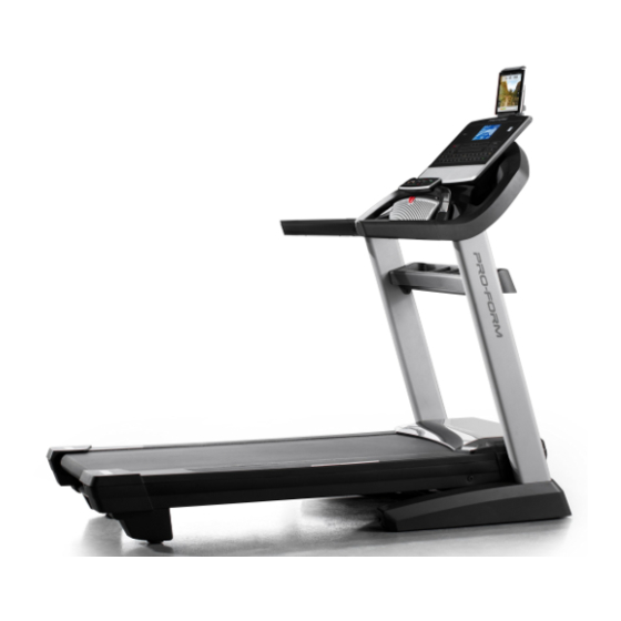
Model No. PFTL15116.0
Serial No.
Write the serial number in the space
above for reference.
Serial Number
Decal
ACTIVATE YOUR
WARRANTY
To register your product and
activate your warranty today,
go to www.proformservice.com/
registration.
CUSTOMER CARE
For service at any time, go to
www.proformservice.com.
Or call 1-888-533-1333
Mon.–Fri. 6 a.m.–6 p.m. MT
Sat. 8 a.m.–12 p.m. MT
Please do not contact the store.
CAUTION
Read all precautions and instruc-
tions in this manual before using
this equipment. Save this manual
for future reference.
USER'S MANUAL
Advertisement
Table of Contents

Related Manuals for Pro-Form PFTL15116.0


Summary of Contents for Pro-Form PFTL15116.0
- Page 1 Model No. PFTL15116.0 USER’S MANUAL Serial No. Write the serial number in the space above for reference. Serial Number Decal ACTIVATE YOUR WARRANTY To register your product and activate your warranty today, go to www.proformservice.com/ registration. CUSTOMER CARE For service at any time, go to www.proformservice.com.
-
Page 2: Table Of Contents
TABLE OF CONTENTS WARNING DECAL PLACEMENT ............. . . 2 IMPORTANT PRECAUTIONS . -
Page 3: Important Precautions
IMPORTANT PRECAUTIONS WARNING: To reduce the risk of burns, fire, electric shock, or injury to persons, read all important precautions and instructions in this manual and all warnings on your treadmill before using your treadmill. ICON assumes no responsibility for personal injury or property damage sus- tained by or through the use of this product. - Page 4 19. Always stand on the foot rails when starting able to safely lift 45 lbs. (20 kg) to move the or stopping the walking belt. Always hold the treadmill. handrails while using the treadmill. 26. When folding or moving the treadmill, make 20.
- Page 5 STANDARD SERVICE PLANS...
-
Page 6: Before You Begin
BEFORE YOU BEGIN Thank you for selecting the revolutionary PROFORM ® reading this manual, please see the front cover of this PRO 5000 treadmill. The PRO 5000 treadmill offers an manual. To help us assist you, please note the product impressive selection of features designed to make your model number and serial number before contacting us. -
Page 7: Part Identification Chart
PART IDENTIFICATION CHART Use the drawings below to identify small parts used for assembly. The number in parentheses below each draw- ing is the key number of the part, from the PART LIST near the end of this manual. The number following the key number is the quantity used for assembly. -
Page 8: Assembly
ASSEMBLY • To hire an authorized service technician to • Left parts are marked “L” or “Left” and right parts assemble the treadmill, call 1-800-445-2480. are marked “R” or “Right.” • Assembly requires two persons. • To identify small parts, see page 7. •... - Page 9 2. Make sure that the power cord is unplugged. Remove the tie securing the Upright Wire (83) to the front of the Base (93). Next, identify the Right Upright (84). Have a second person hold the Right Upright near the Base (93).
- Page 10 4. Hold the Right Upright (84) against the Base (93). Make sure not to pinch the Upright Wire (83). Attach the Right Upright (84) with two 3/8" x 2 3/4" Screws (23), two 3/8" x 1 1/4" Screws (20), and four 3/8" Star Washers (25) as shown; do not fully tighten the Screws yet.
- Page 11 6. Attach the two Handrails (74) to the Right and Left Uprights (84, 91) with the four 5/16" x 2" Screws (2) that you removed in step 5 and four 5/16" Star Washers (8); start all four Screws, and then tighten them. Be careful not to pinch the Upright Wire (83) on the right side.
- Page 12 8. See the inset drawing. Connect the Upright Wire (83) to the console wire (H). The connec- tors should slide together easily and snap into place. If they do not, turn one connector and try again. IF YOU DO NOT CONNECT THE CONNECTORS PROPERLY, THE CONSOLE MAY BECOME DAMAGED WHEN YOU TURN ON THE POWER.
- Page 13 10. IMPORTANT: To avoid damaging the Pulse Crossbar (80), do not use power tools, and do not overtighten the #10 x 3/4" Screws (6) or the 1/4" x 5/8" Screws (99). Tighten two 1/4" x 5/8" Screws (99) with two 1/4" Star Washers (77), and two #10 x 3/4"...
- Page 14 12. Attach the Left Handrail Bottom Cover (75) to the left Handrail (74) with two #8 x 3/4" Truss Head Screws (24); start both Truss Head Screws, and then tighten them. Be careful not to over- tighten the Truss Head Screws. Attach the Right Handrail Bottom Cover (82) to the right Handrail (74) as described above.
- Page 15 15. Attach the Tray (97) to the Upright Crossbar (76) with four #8 x 3/4" Truss Head Screws (24); start all four Truss Head Screws, and then tighten them. 16. Raise the Frame (52) to the upright position. IMPORTANT: Have a second person hold the Frame until step 18 is completed.
- Page 16 17. Remove the 5/16" Nut (9) and the 5/16" x 1 3/4" Bolt (7) from the bracket on the Base (93). Next, orient the Storage Latch (56) as shown. Attach the lower end of the Storage Latch (56) to the bracket on the Base (93) with the 5/16" x 1 3/4"...
- Page 17 19. Firmly tighten the four 3/8" x 2 3/4" Screws (23) and the four 3/8" x 1 1/4" Screws (20). Next, slide and the Left and Right Upright Covers (89, 90) down until they snap into place. 20. Attach the Tablet Holder (100) to the console assembly (G) with four M4 x 16mm Screws (3);...
-
Page 18: The Chest Heart Rate Monitor
THE CHEST HEART RATE MONITOR HOW TO PUT ON THE HEART RATE MONITOR • Store the heart rate monitor in a warm, dry place. Do not store the heart rate monitor in a plastic bag or If the heart rate monitor looks like the one shown other container that may trap moisture. -
Page 19: How To Use The Treadmill
HOW TO USE THE TREADMILL HOW TO CONNECT THE POWER CORD more amps. To avoid overloading the circuit, do not plug other electrical devices, except for low- Use a Surge Suppressor power devices such as cell phone chargers, into the surge suppressor or into an outlet on the same Your treadmill, like other electronic equipment, can be circuit. - Page 20 CONSOLE DIAGRAM MAKE YOUR FITNESS GOALS A REALITY WITH FEATURES OF THE CONSOLE IFIT.COM The advanced treadmill console offers a selection of With your new iFit-enabled fitness equipment, you can features designed to make your workouts more effec- use an array of features on iFit.com to make your fit- tive and enjoyable.
- Page 21 HOW TO TURN ON THE POWER HOW TO USE THE TOUCH SCREEN IMPORTANT: If the treadmill has been exposed to The console features a tablet with a full-color touch cold temperatures, allow it to warm to room tem- screen. The following information will help you become perature before you turn on the power.
- Page 22 HOW TO SET UP THE CONSOLE The console is now ready for you to begin working out. The following pages explain the various workouts and Before using the treadmill for the first time, set up the other features that the console offers. console.
- Page 23 HOW TO USE THE MANUAL MODE If you press one of the numbered speed buttons, the walking belt will gradually change speed until it 1. Insert the key into the console. reaches the selected speed setting. See HOW TO TURN ON THE POWER on page To select a speed setting that includes a decimal—...
- Page 24 As you walk or run on the treadmill, the screen can 6. Measure your heart rate if desired. show the following workout information: Note: If you use the handgrip heart rate moni- • The incline level of the treadmill tor and the chest heart rate monitor at the same time, the console will not display your heart •...
- Page 25 8. When you are finished exercising, remove the 3. Start the workout. key from the console. Touch the Start Workout button to start the work- Step onto the walking platform and touch the home out. A moment after you touch the button, the button or the back button on the screen or press walking belt will begin to move.
- Page 26 To pause the workout, touch either the back button HOW TO USE A SET-A-GOAL WORKOUT or the home button in the lower-left corner of the screen, or press the Stop button on the console. 1. Insert the key into the console. To continue the workout, touch the Resume button or press the Run button on the console.
- Page 27 The workout will function in the same way as the HOW TO USE AN IFIT WORKOUT manual mode (see pages 23 to 25). Note: To use an iFit workout, you must have access The workout will continue until you reach the goal to a wireless network (see HOW TO USE THE that you set.
- Page 28 To compete in a race that you have previously 7. Measure your heart rate if desired. scheduled, touch the Compete button. To view your Workout History, touch the Track button. To use a See step 6 on page 24. set-a-goal workout, touch the Set A Goal button (see page 26).
- Page 29 3. Select a language. To turn on or turn off the display demo mode, fi rst touch the Demo Mode button. Next, touch the On To select a language, touch the Language button checkbox or the Off checkbox. Then, touch the and select the desired language.
- Page 30 Note: If a passcode is enabled, the console will To use the keyboard, see HOW TO USE THE TOUCH regularly ask for you to enter the passcode. The SCREEN on page 21. console will remain locked until the correct pass- code is entered.
- Page 31 HOW TO USE THE MAINTENANCE MODE 4. Calibrate the incline system of the treadmill. IMPORTANT: Some of the features described may Touch the Calibrate Incline button. Then, touch the not be enabled. Occasionally, a fi rmware update may Begin button to calibrate the incline system. The cause your console to function slightly differently.
- Page 32 HOW TO USE THE WIRELESS NETWORK MODE An information box will ask if you want to connect to the wireless network. Touch the Connect button The console features a wireless network mode that to connect to the network or touch the Cancel but- allows you to set up a wireless network connection.
-
Page 33: Fcc Information
HOW TO USE THE TABLET HOLDER IMPORTANT: The tablet holder is designed for use with most full-size tablets. Do not place any other Tablet Holder electronic device or object in the tablet holder. To insert a tablet into the tablet holder, set the bottom edge of the tablet in the tray. -
Page 34: How To Fold And Move The Treadmill
HOW TO FOLD AND MOVE THE TREADMILL HOW TO FOLD THE TREADMILL HOW TO MOVE THE TREADMILL To avoid damaging the treadmill, adjust the incline Before moving the treadmill, fold it as described at the to zero before you fold the treadmill. Then, remove left. -
Page 35: Maintenance And Troubleshooting
MAINTENANCE AND TROUBLESHOOTING MAINTENANCE b. After the power cord has been plugged in, make sure that the key is inserted into the console. Regular maintenance is important for optimal perfor- mance and to reduce wear. Inspect and properly tighten c. Check the power switch located on the treadmill all parts each time the treadmill is used. - Page 36 SYMPTOM: The incline of the treadmill does not c. Your treadmill features a walking belt coated with change correctly high-performance lubricant. IMPORTANT: Never apply silicone spray or other substances to a. Calibrate the incline system of the treadmill (see the walking belt or the walking platform unless step 4 on page 31).
- Page 37 b. If the walking belt slips when walked on, fi rst SYMPTOM: The tablet holder does not stay in place remove the key and UNPLUG THE POWER CORD. Using the hex key, turn both idler roller a. Rotate the tablet holder backwards. Then, tighten screws clockwise, 1/4 of a turn.
-
Page 38: Exercise Guidelines
EXERCISE GUIDELINES Burning Fat—To burn fat effectively, you must exer- WARNING: cise at a low intensity level for a sustained period of Before beginning this time. During the first few minutes of exercise, your or any exercise program, consult your physi- body uses carbohydrate calories for energy. -
Page 39: Part List
PART LIST Model No. PFTL15116.0 R1016A Key No. Qty. Description Key No. Qty. Description 5/16" x 3/4" Screw Storage Latch 5/16" x 2" Screw Right Frame Cover M4 x 16mm Screw #8 x 1/2" Screw 5/16" x 2 1/4" Bolt Idler Roller #8 x 3/4"... -
Page 40: Exploded Drawing
EXPLODED DRAWING A Model No. PFTL15116.0 R1016A... - Page 41 EXPLODED DRAWING B Model No. PFTL15116.0 R1016A...
- Page 42 EXPLODED DRAWING C Model No. PFTL15116.0 R1016A...
- Page 43 EXPLODED DRAWING D Model No. PFTL15116.0 R1016A...
-
Page 44: Ordering Replacement Parts
ORDERING REPLACEMENT PARTS To order replacement parts, please see the front cover of this manual. To help us assist you, be prepared to provide the following information when contacting us: • the model number and serial number of the product (see the front cover of this manual) •...