Advertisement
Quick Links
harman/kardon
harman/kardon
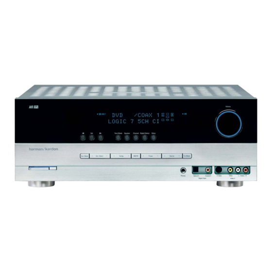
5 X 40W 5.1 CHANNEL A/V RECEIVER
ESD WARNING........................
LEAKAGE TESTING..................
BASIC SPECIFICATIONS..........
TROUBLESHOOTING GUIDE.....
PROCESSOR RESET...............
PACKAGE LIST AND PARTS.......
DISASSEMBLY
UNIT EXPLODED VIEW AND PARTS
Released 2007
Discontinued XXXX
AVR145
SERVICE MANUAL
harman/kardon, Inc.
250 Crossways Park Dr.
Woodbury, New York, 11797
CONTENTS
2
ELECTRICAL PARTS LIST....
3
SEMICONDUCTOR PINOUTS
4
PCB DRAWINGS..................
5
BLOCK DIAGRAM.................
5
WIRING DIAGRAM................
6
AMP BIAS ADJUSTMENT
7
SCHEMATIC DIAGRAMS.......
11
Rev 0, 10/2007
AVR 145/230 service manual
12
48
119
126
127
128
129
Page 1 of 135
Advertisement

Related Manuals for Harman Kardon AVR145/230


Summary of Contents for Harman Kardon AVR145/230
- Page 1 harman/kardon AVR 145/230 service manual harman/kardon AVR145 5 X 40W 5.1 CHANNEL A/V RECEIVER SERVICE MANUAL CONTENTS ESD WARNING......ELECTRICAL PARTS LIST..LEAKAGE TESTING....SEMICONDUCTOR PINOUTS BASIC SPECIFICATIONS..PCB DRAWINGS....TROUBLESHOOTING GUIDE..BLOCK DIAGRAM....PROCESSOR RESET....WIRING DIAGRAM....PACKAGE LIST AND PARTS..AMP BIAS ADJUSTMENT DISASSEMBLY SCHEMATIC DIAGRAMS..
- Page 2 harman/kardon AVR 145/230 service manual harman/kardo AVR145 ELECTROSTATICALLY SENSITIVE DEVICES Some semiconductor (solid state) devices can be damaged easily by static electricity. Such components commonly are called Electrostatically Sensitive (ES) Devices. Examples of typical ES devices are integrated circuits and some field effect transistors and semiconductor "chip"...
- Page 3 harman/kardon AVR 145/230 service manual SAFETY PRECAUTIONS The following check should be performed for the continued protection of the customer and service technician. LEAKAGE CURRENT CHECK Measure leakage current to a known earth ground (water pipe, conduit, etc.) by connecting a leakage current tester between the earth ground and all exposed metal parts of the appliance (input/output terminals, screwheads, metal overlays, control shaft, etc.).
- Page 4 AVR 145/230 service manual Technical Specifications AVR145/230 Audio Section FM Tuner Section Stereo Mode Frequency Range 87.5–108MHz Continuous Average Power (FTC) Usable Sensitivity IHF 1.3 µV/13.2dBf Signal-to-Noise Ratio Mono/Stereo: 70/68dB (DIN) 50 Watts per channel, 20Hz–20kHz, Distortion Mono/Stereo: 0.2/0.3% @ <...
- Page 5 • Amplifier is in protection mode • Contact your local Harman Kardon service center due to internal problems No sound from surround or • Incorrect surround mode • Select a mode other than Stereo center speakers •...
- Page 6 AVR 145/230 service manual AVR145/230 2. Package Drawing 1. Instruction manual ass'y - Accessories ACCESSORY-1 FM 1 POLE ANT POLY BAG AM LOOP ANTENNA ASS'Y BATTERY ASS'Y SNOW PAD (L) SNOW PAD (R) REMOCON IMAGE BROCHURES STAPLE TRANSMITTER ASS'Y...
- Page 7 AVR 145/230 service manual DISASSEMBLY AVR145/230 1. Removing the Top Cabinet 3. Removing the Rear Panel Remove the Screws Remove the Screws 11 12 21 22 4. Removing the Main PCB Remove the Screws 2. Removing the Front Panel...
- Page 8 harman/kardon AVR145 AVR145 DISASSEMBLY PROCEDURE 1 TOP-CABINET (21) REMOVAL 1. Remove 13 screws (S1,S7) and then remove the Top-cabinet. FRONT PANEL ASS’Y REMOVAL 1. Remove the Top-cabinet, referring to the previous step 1. 2. Disconnect the card cable between connector (CN72-17p) on the FIP PCB (37-1) and connector (CN72) on the Input PCB (39-1). 3.
- Page 9 harman/kardon AVR145 8 TUNER MODULE (42) REMOVAL 1. Remove the Top-cabinet, referring to the previous step 1. 2. Disconnect the card cable between connector (CON1-13p) on the Tuner module (42) and connector (CN13) on Input PCB (39-1). 3. Remove 2 screws (S8) and then remove the Tuner Module (42). 9 VIDEO PCB (41) REMOVAL 1.
- Page 10 harman/kardon AVR145 14 MAIN PCB ASS’Y (38-1) REMOVAL 1. Remove the Top-cabinet, referring to the previous step 1. 2. Remove the Tuner module (42), referring to the previous step8. 3. Remove the Video PCB (41) referring to the previous step9. 4.
- Page 11 AVR 145/230 service manual AVR145/230 EXPLODED VIEW 37-7 39-2 40-1 40-3 40-4 39-1 40-5 40-2 38-1 38-2 39-3 40-2 DESCRIPTION PARTS NO. Q,ty Weright ORNAMENT,VOLUME CGU1A318Z CAP,VOLUME CGX1A338MBC63 HOLDER,VOLUME CMH1A214 INDICATOR,VOLUME CGL1A222 WINDOW ASS'Y CGUAVR145 WINDOW,FIP CGU1A399Y BADGE,MODEL CGB1A168Z...
- Page 12 AVR 145/230 service manual AVR145/230 Electrical Parts List Value Ref. # Part Number Description CGL1A222 INDICATOR , VOLUME INDICATOR CGUAVR145 WINDOW ASS'Y ASS'Y CGB1A168Z BADGE , AVR145 BADGE CGU1A399Y WINDOW , FIP FIP WINDOW CGU1A318Z ORNAMENT , VOLUME ORNAMENT...
- Page 13 harman/kardon AVR 145/230 service manual BOTTOM CHASSIS ASS'Y Value Ref. # Part Number Description CHE36-3 CLAMPER , WIRE CLAMPER CHG1A104Z CUSHION , RUBBER CUSHION CHG1A160Z CUSHION , RUBBER CUSHION CHG1A360 CUSHION , FOOT CUSHION CHS1A032 HEMELON TAPE TAPE CJA2B043ZA CORD , POWER(EUR) QDR-7100CC CKF4A319Z PANEL , REAR...
- Page 14 AVR 145/230 service manual FRONT PCB ASSY Value Ref. # Part Number Description COP11910E FRONT PCB ASS'Y(AVR145/230) ASS'Y C714 HCBS1H151KBT CAP , CERAMIC 150UF 50V K C716 CCEA1AH331T CAP , ELECT 330UF 10V C719 HCBS1H102KBT CAP , CERAMIC 1000PF 50V K...
- Page 15 harman/kardon AVR 145/230 service manual FRONT PCB ASSY Value Ref. # Part Number Description C896 HCBS1H223ZFT CAP , CERAMIC 0.023UF 50V Z C897 CCEA1AH471T CAP , ELECT 470UF 10V C901 HCBS1H390JT CAP , CERAMIC 39PF 50V Z C903 CCEA1HKS2R2T CAP , ELECT 2.2UF 50V SMALL SIZE C905 CCEA1HKS2R2T...
- Page 16 harman/kardon AVR 145/230 service manual FRONT PCB ASSY Value Ref. # Part Number Description R768 CRD20TF1801T RES , CARBON 1.8K 1/5W F R769 CRD20TF2701T RES , CARBON 2.7K 1/5W F R781 CRD20TJ102T RES , CARBON 1K OHM 1/5W J R783 CRD20TJ102T RES , CARBON 1K OHM 1/5W J...
- Page 17 harman/kardon AVR 145/230 service manual FRONT PCB ASSY Value Ref. # Part Number Description R956 CRD20TJ1R0T RES , CARBON 1 OHM 1/5W J S701 HST1A020ZT SW , TACT 1A020 S702 HST1A020ZT SW , TACT 1A020 S703 HST1A020ZT SW , TACT 1A020 S704 HST1A020ZT...
- Page 18 SW , PUSH SWITCH VR74 CSR2A037Z ENCODER ENCODER MAIN PCB ASSY Value Ref. # Part Number Description COP11911E MAIN PCB ASS'Y(AVR145/230) ASS'Y CHD3A012R SCREW , SPECIAL Not stocked CHS1A032 HEMELON TAPE TAPE C501 CCEA1HH100T CAP , ELECT 10UF 50V C502...
- Page 19 harman/kardon AVR 145/230 service manual MAIN PCB ASSY Value Ref. # Part Number Description C603 CCCT1H120JC CAP , CERAMIC 12PF 50V C604 CCCT1H120JC CAP , CERAMIC 12PF 50V C605 CCCT1H120JC CAP , CERAMIC 12PF 50V C606 CCCT1H330JC CAP , CERAMIC 33PF 50V C607 CCCT1H330JC...
- Page 20 harman/kardon AVR 145/230 service manual MAIN PCB ASSY Value Ref. # Part Number Description D584 CVD1SS133MT DIODE 1SS133 D585 CVD1SS133MT DIODE 1SS133 D901 CVD1N4003SRT RECT , DIODE 1N4003 D902 CVD1SS133MT DIODE 1SS133 D911 CVD1SS133MT DIODE 1SS133 D912 CVD1SS133MT DIODE 1SS133 D914 CVD1SS133MT DIODE...
- Page 21 harman/kardon AVR 145/230 service manual MAIN PCB ASSY Value Ref. # Part Number Description Q562 HVTKTC3200GRT KTC3200GR Q563 HVTKTC3200GRT KTC3200GR Q564 HVTKTC3200GRT KTC3200GR Q565 HVTKTC3200GRT KTC3200GR Q601 HVTKTA1268GRT KTA1268GR Q602 HVTKTA1268GRT KTA1268GR Q603 HVTKTA1268GRT KTA1268GR Q604 HVTKTA1268GRT KTA1268GR Q605 HVTKTA1268GRT KTA1268GR Q681 HVTKSC2785YT...
- Page 22 harman/kardon AVR 145/230 service manual MAIN PCB ASSY Value Ref. # Part Number Description R531 CRD20TJ221T RES , CARBON 220 OHM 1/5W J R532 CRD20TJ221T RES , CARBON 220 OHM 1/5W J R533 CRD20TJ221T RES , CARBON 220 OHM 1/5W J R534 CRD20TJ221T RES , CARBON...
- Page 23 harman/kardon AVR 145/230 service manual MAIN PCB ASSY Value Ref. # Part Number Description R591 CRD20TJ561T RES , CARBON 560 OHM 1/5W J R592 CRD20TJ561T RES , CARBON 560 OHM 1/5W J R593 CRD20TJ561T RES , CARBON 560 OHM 1/5W J R594 CRD20TJ561T RES , CARBON...
- Page 24 harman/kardon AVR 145/230 service manual MAIN PCB ASSY Value Ref. # Part Number Description R676 CRD20TJ182T RES , CARBON 1.8K OHM 1/5W J R677 CRD20TJ182T RES , CARBON 1.8K OHM 1/5W J R678 CRD20TJ182T RES , CARBON 1.8K OHM 1/5W J R679 CRD20TJ182T RES , CARBON...
- Page 25 harman/kardon AVR 145/230 service manual MAIN PCB ASSY Value Ref. # Part Number Description R947 CRD20TJ223T RES , CARBON 22K OHM 1/5W J R948 CRD25TJ222T RES , CARBON 2.2K OHM 1/5W J R949 CRD20TJ822T RES , CARBON 8.2K OHM 1/5W J R955 CRD20TJ203T RES , CARBON...
- Page 26 harman/kardon AVR 145/230 service manual MAIN PCB ASSY Value Ref. # Part Number Description C904 KCKDKS472ME CAP , CERAMIC(X1/Y2/SC) 0.0047UF/2.5KV C906 CCEA1EH102E CAP , ELECT 1000UF 25V C909 CCET50VKL4682NK CAP , ELECT 6800UF/50V C915 CCET50VKL4682NK CAP , ELECT 6800UF/50V C916 CCET50VKL4682NK CAP , ELECT 6800UF/50V ET01...
- Page 27 T.R , POWER 2SB1560 Q670 HVT2SD2390-OKM T.R , POWER 2SD2390 INPUT PCB ASSY Value Ref. # Part Number Description COP11912E INPUT PCB ASS'Y(AVR145/230) ASS'Y C201 CCUS1H221JA CAP , CHIP 220PF C202 CCUS1H221JA CAP , CHIP 220PF C203 CCUS1H221JA CAP , CHIP...
- Page 28 harman/kardon AVR 145/230 service manual INPUT PCB ASSY Value Ref. # Part Number Description C302 CCUS1H471JA CAP , CHIP 470PF C303 CCUS1H471JA CAP , CHIP 470PF C304 CCUS1H471JA CAP , CHIP 470PF C305 CCUS1H471JA CAP , CHIP 470PF C306 CCUS1H471JA CAP , CHIP 470PF C309...
- Page 29 harman/kardon AVR 145/230 service manual INPUT PCB ASSY Value Ref. # Part Number Description C401 CCUS1H104KC CAP , CHIP 0.1UF C402 CCUS1H471JA CAP , CHIP 470PF C403 CCUS1H471JA CAP , CHIP 470PF C410 CCUS1A105KC CAP , CHIP C411 CCUS1A105KC CAP , CHIP C412 CCUC1C225ZF CAP , CHIP(2.2UF/16V/2012/Y5V)
- Page 30 harman/kardon AVR 145/230 service manual INPUT PCB ASSY Value Ref. # Part Number Description C722 CCUS1H104KC CAP , CHIP 0.1UF C723 CCUS1H473KC CAP , CHIP 0.047UF C725 CCUS1H104KC CAP , CHIP 0.1UF C727 CCUS1H104KC CAP , CHIP 0.1UF C729 CCUS1H104KC CAP , CHIP 0.1UF C731...
- Page 31 harman/kardon AVR 145/230 service manual INPUT PCB ASSY Value Ref. # Part Number Description D216 CVD1SS355T CHIP , DIODE 1SS355T D400 CVD1SS355T CHIP , DIODE 1SS355T D401 CVD1SS355T CHIP , DIODE 1SS355T IC20 CVINJW1197FC2 IC , SW(WITH VOLUME) IC21 HVINJM2068MDTE1 I.C , OP AMP IC22 HVINJM2068MDTE1 I.C , OP AMP IC23...
- Page 32 harman/kardon AVR 145/230 service manual INPUT PCB ASSY Value Ref. # Part Number Description RN80 CRJ104DJ330T RES , 4ARRAY (1608*4) 33 OHM/1608*4 RN81 CRJ104DJ330T RES , 4ARRAY (1608*4) 33 OHM/1608*4 RN82 CRJ104DJ330T RES , 4ARRAY (1608*4) 33 OHM/1608*4 RN83 CRJ104DJ330T RES , 4ARRAY (1608*4) 33 OHM/1608*4 RN84...
- Page 33 harman/kardon AVR 145/230 service manual INPUT PCB ASSY Value Ref. # Part Number Description R248 CRJ10DJ474T RES , CHIP 470K OHM R249 CRJ10DJ474T RES , CHIP 470K OHM R250 CRJ10DJ103T RES , CHIP 10K OHM R253 CRJ10DJ4R7T RES , CHIP 4.7 OHM R254 CRJ10DJ4R7T...
- Page 34 harman/kardon AVR 145/230 service manual INPUT PCB ASSY Value Ref. # Part Number Description R323 CRJ10DJ122T RES , CHIP 1.2K OHM R324 CRJ10DJ512T RES , CHIP 5.1K OHM R325 CRJ10DJ512T RES , CHIP 5.1K OHM R326 CRJ10DJ122T RES , CHIP 1.2K OHM R327 CRJ10DJ122T...
- Page 35 harman/kardon AVR 145/230 service manual INPUT PCB ASSY Value Ref. # Part Number Description R421 CRJ10DJ222T RES , CHIP 2.2K OHM R422 CRJ10DJ474T RES , CHIP 470K OHM R430 CRJ10DJ473T RES , CHIP 47K OHM R431 CRJ10DJ473T RES , CHIP 47K OHM R432 CRJ18AJ221T...
- Page 36 harman/kardon AVR 145/230 service manual INPUT PCB ASSY Value Ref. # Part Number Description R740 CRJ10DJ820T RES , CHIP 820 OHM R741 CRJ10DJ330T RES , CHIP 33 OHM R742 CRJ10DJ330T RES , CHIP 33 OHM R743 CRJ10DJ330T RES , CHIP 33 OHM R744 CRJ10DJ0R0T...
- Page 37 harman/kardon AVR 145/230 service manual INPUT PCB ASSY Value Ref. # Part Number Description C276 CCEA1HH100T CAP , ELECT 10UF 50V C281 CCEA1HH100T CAP , ELECT 10UF 50V C282 CCEA1HH100T CAP , ELECT 10UF 50V C283 CCEA1HH100T CAP , ELECT 10UF 50V C284 CCEA1HH100T...
- Page 38 harman/kardon AVR 145/230 service manual INPUT PCB ASSY Value Ref. # Part Number Description C720 CCEA1AH471T CAP , ELECT 470UF 10V C721 CCEA1AH471T CAP , ELECT 470UF 10V C724 CCEA1AH471T CAP , ELECT 470UF 10V C726 CCEA1CH101T CAP , ELECT 100UF 16V C728 CCEA1AH471T...
- Page 39 HOX24576E150TF CRYSTAL 24.576MHz X703 HOX04332E200C CRYSTAL 4.332MHz POWER PCB ASSY Value Ref. # Part Number Description COP11916E POWER PCB ASS'Y(AVR145/230) ASS'Y C104 HCBS1H103ZFT CAP , CERAMIC 0.01UF 50V C105 HCBS1H103ZFT CAP , CERAMIC 0.01UF 50V C106 CCFT1H104ZF CAP , SEMICONDUCTOR 0.1UF 50V ZF...
- Page 40 harman/kardon AVR 145/230 service manual POWER PCB ASSY Value Ref. # Part Number Description C925 HCQI1H103JZT CAP , MYLAR 0.01UF 50V J C926 HCQI1H103JZT CAP , MYLAR 0.01UF 50V J C927 HCQI1H103JZT CAP , MYLAR 0.01UF 50V J C928 HCQI1H103JZT CAP , MYLAR 0.01UF 50V J C931...
- Page 41 harman/kardon AVR 145/230 service manual POWER PCB ASSY Value Ref. # Part Number Description R761 CRD20TJ750T RES , CARBON 75 OHM 1/5W J R764 CRD20TJ102T RES , CARBON 1K OHM 1/5W J R765 CRD20TJ104T RES , CARBON 100K OHM 1/5W J R766 CRD20TJ472T RES , CARBON...
- Page 42 harman/kardon AVR 145/230 service manual POWER PCB ASSY Value Ref. # Part Number Description CN34 CJP02GA19ZY WAFER, 2PIN WAFER CN35 CJP02GA19ZY WAFER, 2PIN WAFER CN81 CJP08GA01ZY WAFER, STRAIGHT, 8PIN WAFER CN89 CJP02GA01ZY WAFER, STRAIGHT, 2PIN WAFER CN95 CJP03GA19ZY WAFER, STRAIGHT, 3PIN WAFER CN96 CJP09GA01ZY...
- Page 43 AVR 145/230 service manual VIDEO PCB ASSY Value Ref. # Part Number Description COP11917E VIDEO PCB ASS'Y(AVR145/230) ASS'Y C401 CCUS1H101JA CAP , CHIP 100PF C402 CCUS1H101JA CAP , CHIP 100PF C403 CCUS1H101JA CAP , CHIP 100PF C461 CCUS1H223KC CAP , CHIP 0.022UF...
- Page 44 harman/kardon AVR 145/230 service manual VIDEO PCB ASSY Value Ref. # Part Number Description C722 CCUS1H220JA CAP , CHIP 22PF C731 CCUS1H220JA CAP , CHIP 22PF C732 CCUS1H330JA CAP , CHIP 33PF C733 CCUS1H223KC CAP , CHIP 0.022UF C736 CCUS1H223KC CAP , CHIP 0.022UF C741...
- Page 45 harman/kardon AVR 145/230 service manual VIDEO PCB ASSY Value Ref. # Part Number Description R471 CRJ10DJ102T RES , CHIP 1K OHM R485 CRJ10DJ100T RES , CHIP 10 OHM R487 CRJ10DJ100T RES , CHIP 10 OHM R491 CRJ10DJ750T RES , CHIP 75 OHM R492 CRJ10DJ750T...
- Page 46 harman/kardon AVR 145/230 service manual VIDEO PCB ASSY Value Ref. # Part Number Description R623 CRJ10DJ750T RES , CHIP 75 OHM R625 CRJ10DJ750T RES , CHIP 75 OHM R674 CRJ10DJ102T RES , CHIP 1K OHM R675 CRJ10DJ102T RES , CHIP 1K OHM R701 CRJ10DJ0R0T...
- Page 47 harman/kardon AVR 145/230 service manual VIDEO PCB ASSY Value Ref. # Part Number Description C522 CCEA1CH101T CAP , ELECT 100UF 16V C524 CCEA1CH101T CAP , ELECT 100UF 16V C532 CCEA1CH101T CAP , ELECT 100UF 16V C533 CCEA1CH101T CAP , ELECT 100UF 16V C534 CCEA1CH101T...
- Page 48 harman/kardon AVR 145/230 service manual NJM2595 5-INPUT 3-OUTPUT VIDEO SWITCH GENERAL DESCRIPTION PACKAGE OUTLINE The NJM2595 is a 5-input 3-output video switch. Its switches select one from five signals received from VTR,TV,DVD, TV-GAME and others. The NJM2595 is designed for audio items, such as AV amplifier and others.
- Page 49 harman/kardon AVR 145/230 service manual NJM2595 EQUIVALENT CIRCUIT PIN No. PIN NAME INSIDE EQUIVALENT CIRCUIT VOLTAGE Vin1 Vin2 Vin3 Vin4 Vin5 Vout1 Vout2 Vout3 2.1k Vout Page 49 of 135...
- Page 50 harman/kardon AVR 145/230 service manual NJM2595 EQUIVALENT CIRCUIT PIN No. PIN NAME INSIDE EQUIVALENT CIRCUIT VOLTAGE TEST CIRCUIT Vout2.2 Vout2.1 Vout3.2 Vout3.1 75 Ω 75 Ω 75 Ω 75 Ω 0.1µF Vin1 Vin2 75 Ω 75 Ω 100µF 10µF 10µF 1...
- Page 51 harman/kardon AVR 145/230 service manual Page 51 of 135...
- Page 52 harman/kardon AVR 145/230 service manual Page 52 of 135...
- Page 53 harman/kardon AVR 145/230 service manual Page 53 of 135...
- Page 54 harman/kardon AVR 145/230 service manual Page 54 of 135...
- Page 55 harman/kardon AVR 145/230 service manual Page 55 of 135...
- Page 56 harman/kardon AVR 145/230 service manual Page 56 of 135...
- Page 57 harman/kardon AVR 145/230 service manual Page 57 of 135...
- Page 58 harman/kardon AVR 145/230 service manual Page 58 of 135...
- Page 59 harman/kardon AVR 145/230 service manual Page 59 of 135...
- Page 60 harman/kardon AVR 145/230 service manual Page 60 of 135...
- Page 61 harman/kardon AVR 145/230 service manual Page 61 of 135...
- Page 62 harman/kardon AVR 145/230 service manual Page 62 of 135...
- Page 63 harman/kardon AVR 145/230 service manual HCF4053B TRIPLE 2-CHANNEL ANALOG MULTIPLEXER/DEMULTIPLEXER LOW "ON" RESISTANCE : 125Ω (Typ.) OVER 15V p.p SIGNAL-INPUT RANGE FOR = 15V HIGH "OFF" RESISTANCE : CHANNEL LEAKAGE ± 100pA (Typ.) at V = 18V BINARY ADDRESS DECODING ON CHIP HIGH DEGREE OF LINEARITY : <...
- Page 64 harman/kardon AVR 145/230 service manual HCF4053B INPUT EQUIVALENT CIRCUIT PIN DESCRIPTION PIN No SYMBOL NAME AND FUNCTION 11, 10, 9 A, B, C Binary Control Inputs Inhibit Inputs 12, 13, 2, 1, ax,ay,bx,by,cx,cy Input/ IN/OUT 5, 3 Output OUT/IN ax or ay OUT/IN bx or by OUT/IN...
- Page 65 harman/kardon AVR 145/230 service manual Page 65 of 135...
- Page 66 harman/kardon AVR 145/230 service manual Page 66 of 135...
- Page 67 harman/kardon AVR 145/230 service manual Page 67 of 135...
- Page 68 harman/kardon AVR 145/230 service manual Page 68 of 135...
- Page 69 harman/kardon AVR 145/230 service manual Page 69 of 135...
- Page 70 harman/kardon AVR 145/230 service manual Page 70 of 135...
- Page 71 harman/kardon AVR 145/230 service manual Page 71 of 135...
- Page 72 harman/kardon AVR 145/230 service manual Page 72 of 135...
- Page 73 harman/kardon AVR 145/230 service manual Page 73 of 135...
- Page 74 harman/kardon AVR 145/230 service manual Page 74 of 135...
- Page 75 harman/kardon AVR 145/230 service manual Page 75 of 135...
- Page 76 harman/kardon AVR 145/230 service manual Page 76 of 135...
- Page 77 harman/kardon AVR 145/230 service manual Page 77 of 135...
- Page 78 harman/kardon AVR 145/230 service manual Page 78 of 135...
- Page 79 harman/kardon AVR 145/230 service manual AK4589 2/8-Channel Audio CODEC with DIR PVSS PVDD X'tal Clock Oscillato r 8 to 3 Recovery Clock MCKO1 Generator Input MCKO2 Selector LRCK2 DAIF A udio BICK2 Decode r SDTO2 DAUX2 A VDD A VSS DVDD Error &...
- Page 80 harman/kardon AVR 145/230 service manual ASAHI KASEI [AK4589] オーダリングガイド -10 ∼ +70°C AK4589VQ 80pin LQFP(0.5mm pitch) 評価ボード AKD4589 ピン配置 TEST1 INT1 BOUT TVDD DVDD AVSS DVSS AVDD VREFH XT I VCOM (Top View) TEST3 MCKO2 MCKO1 ROUT1+ COUT ROUT1- UOUT LOUT1+ VOUT LOUT1-...
- Page 81 harman/kardon AVR 145/230 service manual ASAHI KASEI [AK4589] AK4588 との相違点 Functions AK4588 AK4589 DAC 出力 シングルエンド 差動 DAC S/(N+D) 90dB 94dB DAC S/N 106dB 114dB Typ ±2.7Vpp DAC Output voltage Typ 3.0Vpp DAC AOUT AOUT=0.6xVREFH AOUT=0.54xVREFH Load Resistance 5k ohm 2k ohm ±1.0 Frequency Response 80kHz...
- Page 82 harman/kardon AVR 145/230 service manual ASAHI KASEI [AK4589] ピン/機能 Pin Name Function INT1 Interrupt 1 Pin Block-Start Output Pin for Receiver Input BOUT “H” during first 40 flames. TVDD Output Buffer Power Supply Pin, 2.7V∼5.25V DVDD Digital Power Supply Pin, 4.75V∼5.25V DVSS Digital Ground Pin X'tal Output Pin...
- Page 83 harman/kardon AVR 145/230 service manual ASAHI KASEI [AK4589] Pin Name Function Power-Down Mode Pin When “L”, the AK4589 is powered-down, all digital output pins go “L”, all registers are reset. When CAD1/0 pins are changed, the AK4589 should be reset by PDN pin. Master Mode Select Pin MASTER “H”: Master mode, “L”: Slave mode...
- Page 84 harman/kardon AVR 145/230 service manual ASAHI KASEI [AK4589] Pin Name Function AVDD Analog Power Supply Pin, 4.75V∼5.25V Analog Ground Pin, 0V AVSS Receiver Channel 0 Pin (Internal biased pin. Internally biased at PVDD/2) No Connect pin No internal bonding. This pin should be connected to PVSS. Receiver Channel 1 Pin (Internal biased pin.
- Page 85 harman/kardon AVR 145/230 service manual ASAHI KASEI [AK4589] 使用しないピンの処理について 使用しない入出力ピンは下記の設定を行い、適切に処理して下さい。 Classification Pin Name Setting Analog RX0-7, LOUT1-4, ROUT1-4, LIN, RIN These pins should be open. INT0-1, BOUT, XTO, MCKO1-2, COUT, UOUT, These pins should be open. VOUT, SDTO1-2, CDTO, DZF1-2, TX1-0 Digital These pins should be connected to DVSS.
- Page 86 harman/kardon AVR 145/230 service manual Page 86 of 135...
- Page 87 harman/kardon AVR 145/230 service manual M29W800DT M29W800DB 8 Mbit (1Mb x8 or 512Kb x16, Boot Block) 3V Supply Flash Memory FEATURES SUMMARY SUPPLY VOLTAGE Figure 1. Packages – = 2.7V to 3.6V for Program, Erase and Read ACCESS TIMES: 45, 70, 90ns PROGRAMMING TIME –...
- Page 88 harman/kardon AVR 145/230 service manual M29W800DT, M29W800DB SUMMARY DESCRIPTION The M29W800D is a 8 Mbit (1Mb x8 or 512Kb x16) command set required to control the memory is non-volatile memory that can be read, erased and consistent with JEDEC standards. reprogrammed.
- Page 89 harman/kardon AVR 145/230 service manual M29W800DT, M29W800DB Figure 3. SO Connections Figure 4. TSOP Connections BYTE V SS DQ15A–1 DQ14 DQ13 DQ12 V CC M29W800DT M29W800DT M29W800DB DQ11 M29W800DB BYTE V SS V SS DQ10 DQ15A–1 DQ14 DQ13 DQ10 DQ12 V SS DQ11 V CC...
- Page 90 harman/kardon AVR 145/230 service manual M29W800DT, M29W800DB Figure 6. Block Addresses (x8) M29W800DT M29W800DB Top Boot Block Addresses (x8) Bottom Boot Block Addresses (x8) FFFFFh FFFFFh 16 KByte 64 KByte FC000h F0000h FBFFFh EFFFFh 8 KByte 64 KByte FA000h E0000h F9FFFh Total of 15 8 KByte...
- Page 91 harman/kardon AVR 145/230 service manual M29W800DT, M29W800DB Figure 7. Block Addresses (x16) M29W800DT M29W800DB Top Boot Block Addresses (x16) Bottom Boot Block Addresses (x16) 7FFFFh 7FFFFh 8 KWord 32 KWord 7E000h 78000h 7DFFFh 77FFFh 4 KWord 32 KWord 7D000h 70000h 7CFFFh Total of 15 4 KWord...
- Page 92 harman/kardon AVR 145/230 service manual M29W800DT, M29W800DB SIGNAL DESCRIPTIONS Figure 2., Logic Diagram, Table , whichever occurs last. See the Ready/Busy RHEL 1., Signal Names, for a brief overview of the sig- Output section, Table 15. Figure 15., Reset/ nals connected to this device. Block Temporary Unprotect AC Waveforms, for more details.
- Page 93 harman/kardon AVR 145/230 service manual M29W800DT, M29W800DB BUS OPERATIONS There are five standard bus operations that control ance state. To reduce the Supply Current to the the device. These are Bus Read, Bus Write, Out- Standby Supply Current, I , Chip Enable should put Disable, Standby and Automatic Standby.
- Page 94 harman/kardon AVR 145/230 service manual M29W800DT, M29W800DB Table 3. Bus Operations, BYTE = V Address Inputs Data Inputs/Outputs Operation A0-A18 DQ15A–1, DQ14-DQ0 Bus Read Cell Address Data Output Bus Write Command Address Data Input Output Disable Hi-Z Standby Hi-Z A0 = V , A1 = V , A9 = V Read Manufacturer...
- Page 95 harman/kardon AVR 145/230 service manual M29W800DT, M29W800DB After the program operation has completed the During the erase operation the memory will ignore all commands. It is not possible to issue any com- memory will return to the Read mode, unless an error has occurred.
- Page 96 harman/kardon AVR 145/230 service manual M29W800DT, M29W800DB Erase Suspend Command. The Erase Suspend mode before the Resume command will be ac- cepted. Command may be used to temporarily suspend a Block Erase operation and return the memory to Erase Resume Command. The Erase Resume Read mode.
- Page 97 harman/kardon AVR 145/230 service manual Video Switch · 75Ω driver · Y/C mix MM1501 MITSUMI Video Switch · 75Ω driver · Y/C mix Monolithic IC MM1501 Series Outline This IC extends the series of ICs for video/audio signal switching, with a 2-input 1-output single video switch, video signal/chroma signal 75Ω...
- Page 98 harman/kardon AVR 145/230 service manual Video Switch · 75Ω driver · Y/C mix MM1501 MITSUMI Block Diagram MM1501 MM1502 MM1503 MM1504 MM1505 MM1506 Page 98 of 135...
- Page 99 harman/kardon AVR 145/230 service manual Video Switch · 75Ω driver · Y/C mix MM1501 MITSUMI MM1507 MM1508 MM1509 MM1510 MM1511 MM1512 Page 99 of 135...
- Page 100 harman/kardon AVR 145/230 service manual Page 100 of 135...
- Page 101 harman/kardon AVR 145/230 service manual Page 101 of 135...
- Page 102 harman/kardon AVR 145/230 service manual www.fairchildsemi.com MC78XX/LM78XX/MC78XXA 3-Terminal 1A Positive Voltage Regulator Features Description • Output Current up to 1A The MC78XX/LM78XX/MC78XXA series of three • Output Voltages of 5, 6, 8, 9, 10, 12, 15, 18, 24V terminal positive regulators are available in the •...
- Page 103 harman/kardon AVR 145/230 service manual Page 103 of 135...
- Page 104 harman/kardon AVR 145/230 service manual Page 104 of 135...
- Page 105 harman/kardon AVR 145/230 service manual Page 105 of 135...
- Page 106 harman/kardon AVR 145/230 service manual M24C64 M24C32 64Kbit and 32Kbit Serial I²C Bus EEPROM FEATURES SUMMARY Two-Wire I C Serial Interface Figure 1. Packages Supports 400kHz Protocol Single Supply Voltage: – 4.5 to 5.5V for M24Cxx – 2.5 to 5.5V for M24Cxx-W –...
- Page 107 harman/kardon AVR 145/230 service manual M24C64, M24C32 SUMMARY DESCRIPTION These I C-compatible electrically erasable pro- Table 2. Signal Names grammable memory (EEPROM) devices are orga- E0, E1, E2 Chip Enable nized as 8192 x 8 bits (M24C64) and 4096 x 8 bits (M24C32).
- Page 108 harman/kardon AVR 145/230 service manual M24C64, M24C32 SIGNAL DESCRIPTION Serial Clock (SCL). This input signal is used to rial Data (SDA) to V (Figure 4. indicates how strobe all data in and out of the device. In applica- the value of the pull-up resistor can be calculated). tions where this signal is used by slave devices to Chip Enable (E0, E1, E2).
- Page 109 harman/kardon AVR 145/230 service manual M24C64, M24C32 MEMORY ORGANIZATION The memory is organized as shown in Figure Figure 6. Block Diagram High Voltage Control Logic Generator I/O Shift Register Address Register Data and Counter Register 1 Page X Decoder AI06899 7/26 Page 109 of 135...
- Page 110 harman/kardon AVR 145/230 service manual M24C64, M24C32 DEVICE OPERATION The device supports the I C protocol. This is sum- Data (SDA) Low to acknowledge the receipt of the marized in Figure 5.. Any device that sends data eight data bits. on to the bus is defined to be a transmitter, and Data Input any device that reads the data to be a receiver.
- Page 111 harman/kardon AVR 145/230 service manual M24C64, M24C32 Figure 7. Write Mode Sequences with WC=1 (data write inhibited) NO ACK BYTE WRITE DEV SEL BYTE ADDR BYTE ADDR DATA IN NO ACK PAGE WRITE DEV SEL BYTE ADDR BYTE ADDR DATA IN 1 DATA IN 2 WC (cont'd) NO ACK...
- Page 112 harman/kardon AVR 145/230 service manual M24C64, M24C32 Page Write The bus master sends from 1 to 32 bytes of data, each of which is acknowledged by the device if The Page Write mode allows up to 32 bytes to be Write Control (WC) is Low.
- Page 113 harman/kardon AVR 145/230 service manual M24C64, M24C32 Figure 9. Write Cycle Polling Flowchart using ACK WRITE Cycle in Progress START Condition DEVICE SELECT with RW = 0 Returned First byte of instruction with RW = 0 already decoded by the device Next Operation is Addressing the...
- Page 114 harman/kardon AVR 145/230 service manual M24C64, M24C32 Figure 10. Read Mode Sequences NO ACK CURRENT ADDRESS DEV SEL DATA OUT READ NO ACK RANDOM ADDRESS DEV SEL * BYTE ADDR BYTE ADDR DEV SEL * DATA OUT READ NO ACK SEQUENTIAL CURRENT DEV SEL...
- Page 115 harman/kardon AVR 145/230 service manual LOW VOLTAGE DETECTOR × 5VT SERIES × PIN CONFIGURATION TO-92 • SOT-89 SOT-23-5 • • (mark side) (mark side) (mark side) PIN DESCRIPTION TO-92 SOT-89 SOT-23-5 • • • Pin No. Symbol Pin No. Symbol Pin No.
- Page 116 harman/kardon AVR 145/230 service manual VOL TAGE DETECTOR × 5VL SERIES × PIN CONFIGURATION TO-92 SOT-89 SOT-23-5 • • • (mark side) (mark side) (mark side) PIN DESCRIPTION TO-92 SOT-89 SOT-23-5 • • • Pin No Symbol Pin No Symbol Pin No Symbol Page 116 of 135...
- Page 117 harman/kardon AVR 145/230 service manual Page 117 of 135...
- Page 118 harman/kardon AVR 145/230 service manual Page 118 of 135...
- Page 119 harman/kardon AVR 145/230 service manual Page 119 of 135...
- Page 120 harman/kardon AVR 145/230 service manual Page 120 of 135...
- Page 121 harman/kardon AVR 145/230 service manual Page 121 of 135...
- Page 122 harman/kardon AVR 145/230 service manual Page 122 of 135...
- Page 123 harman/kardon AVR 145/230 service manual Page 123 of 135...
- Page 124 harman/kardon AVR 145/230 service manual Page 124 of 135...
- Page 125 harman/kardon AVR 145/230 service manual Page 125 of 135...
- Page 126 harman/kardon AVR 145/230 service manual BLOCK DIAGRAM Page 126 of 135...
- Page 127 harman/kardon AVR 145/230 service manual Page 127 of 135...
- Page 128 harman/kardon AVR 145/230 service manual AMPLIFIER SECTION BIAS ADJUSTMENT Measurement condition .No input signal or volume position is minimum. Standard value .Ideal current = 48mA (± 5%) .Ideal DC Voltage = 25.92mV (± 5%) DC EVM CUP11911Y (MAIN PCB) CN61 CN64 CN63 CN65...
- Page 129 harman/kardon AVR 145/230 service manual Page 129 of 135...
- Page 130 harman/kardon AVR 145/230 service manual Page 130 of 135...
- Page 131 harman/kardon AVR 145/230 service manual Page 131 of 135...
- Page 132 harman/kardon AVR 145/230 service manual Page 132 of 135...
- Page 133 harman/kardon AVR 145/230 service manual Page 133 of 135...
- Page 134 harman/kardon AVR 145/230 service manual Page 134 of 135...
- Page 135 harman/kardon AVR 145/230 service manual Page 135 of 135...