Table of Contents
Advertisement
Quick Links
Safe Operation Practices • Set-Up • Operation • Maintenance • Service • Troubleshooting • Warranty
O
'
M
peratOr
s
anual
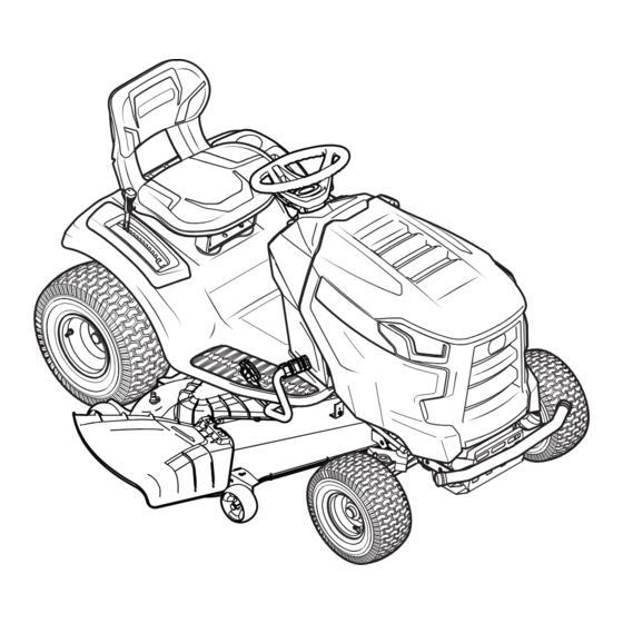
Lawn Tractor
NOTE: This Operator's Manual covers several models. Tractor features may vary by model. Not all features in this manual are
applicable to all tractor models and the tractor depicted may differ from yours.
WARNING
READ AND FOLLOW ALL SAFETY RULES AND INSTRUCTIONS IN THIS MANUAL
BEFORE ATTEMPTING TO OPERATE THIS MACHINE.
FAILURE TO COMPLY WITH THESE INSTRUCTIONS MAY RESULT IN PERSONAL INJURY.
MTD LLC, P.O. BOX 361131 CLEVELAND, OHIO 44136-0019
Printed In USA
Form No. 769-10869
(June 9, 2015)
Advertisement
Table of Contents

Related Manuals for MTD Rover 13APA1KS333


Summary of Contents for MTD Rover 13APA1KS333
- Page 1 READ AND FOLLOW ALL SAFETY RULES AND INSTRUCTIONS IN THIS MANUAL BEFORE ATTEMPTING TO OPERATE THIS MACHINE. FAILURE TO COMPLY WITH THESE INSTRUCTIONS MAY RESULT IN PERSONAL INJURY. MTD LLC, P.O. BOX 361131 CLEVELAND, OHIO 44136-0019 Printed In USA Form No. 769-10869...
-
Page 2: Table Of Contents
Visit us on the web at www.mtdproducts.com See How-to Maintenance and Parts Installation Videos at www.mtdparts.com/KnowledgeCenter ◊ Call a Customer Support Representative at 1300 951 594 ◊ Write to MTD Products Australia Pty Ltd. • P.O. Box 376 • Dandenong. Vic. • 3175... -
Page 3: Safe Operation Practices
Important Safe Operation Practices WARNING! This symbol points out important safety instructions which, if not followed, could endanger the personal safety and/or property of yourself and others. Read and follow all instructions in this manual before attempting to operate this machine. Failure to comply with these instructions may result in personal injury. - Page 4 Slope Operation A missing or damaged discharge cover can cause blade contact or thrown object injuries. Slopes are a major factor related to loss of control and tip-over Stop the blade(s) when crossing gravel drives, walks, or accidents which can result in severe injury or death. All slopes roads and while not cutting grass.
- Page 5 Service Children Tragic accidents can occur if the operator is not alert to the Safe Handling of Gasoline: presence of children. Children are often attracted to the machine and the mowing activity. They do not understand To avoid personal injury or property damage use extreme the dangers.
- Page 6 Do not modify engine Periodically check to make sure the blades come to complete stop within approximately (5) five seconds after To avoid serious injury or death, do not modify engine in any operating the blade disengagement control. If the blades way.
- Page 7 Safety Symbols This page depicts and describes safety symbols that may appear on this product. Read, understand, and follow all instructions on the machine before attempting to assemble and operate. Symbol Description READ THE OPERATOR’S MANUAL(S) Read, understand, and follow all instructions in the manual(s) before attempting to assemble and operate DANGER —...
- Page 8 2 — i ection mportant peration racticeS...
-
Page 9: Assembly & Set-Up
Assembly & Set-Up Contents of Crate • One Tractor • One Operator’s Manual • One Engine Operator’s Manual NOTE: This Operator’s Manual covers several models. Tractor Install Operator’s Seat (If necessary) features may vary by model. Not all features in this manual are WARNING! Before operating the tractor, make applicable to all tractor models and the tractor depicted may... - Page 10 Lower Deck Discharge Chute Deflector Rotate the seat into position and secure the seat into place with the previously removed shoulder screws and flange WARNING! Never operate the mower deck lock nuts. Be careful not to crimp or damage the wire without the chute deflector installed and in the harness while installing the seat.
- Page 11 Installing the Dash Cap (If necessary) Secure the steering wheel with the hex bolt from under the cap and torque to 18-22 ft./lbs. To install the dash cap (1), line up the tabs (2) on the dash cap (1) Place the steering wheel cap over the center of the steering with the holes in the upper dash as shown in Figure 3-7.
- Page 12 Installing the Front Bumper (If necessary) Connecting the Battery Cables The hardware for attaching the front bumper is shipped installed CALIFORNIA PROPOSITION 65 WARNING into the bumper. Battery posts, terminals, and related accessories contain lead and lead compounds, chemicals known Remove the four hex screws from the bumper.
- Page 13 Checking Tire Pressure Place the deck lift lever in the desired mowing height setting. WARNING! Equal tire pressure should be Reinsert the shoulder bolt (with each deck wheel) maintained at all times. Refer to the tire sidewall for into the index hole that leaves approximately proper pressure.
-
Page 14: Controls & Features
Controls & Features Fuel Tank Cap Throttle/Choke Hour Meter Control Lever Ignition Module or Throttle Control Lever (If so equipped) Forward Drive Pedal Reverse Drive Pedal PTO Switch (If Choke Control Brake Pedal so equipped) PTO Handle (If so equipped) Park Brake/Cruise Control Lever Deck Lift Lever... - Page 15 Throttle/Choke Control Lever Ignition Module (If so equipped) WARNING! Never leave a running The throttle/choke control lever is located on the left machine unattended. side of the tractor’s dash panel. This lever controls the Always disengage speed of the engine and, when pushed all the way PTO, set parking brake, stop forward, past the detent position closes the choke for engine and remove key to prevent...
- Page 16 Park Brake/Cruise Control Lever Low Oil (If so equipped) The letters “LO” followed by the letters “OIL”, then followed by the meter’s accumulated time will indicate the tractor is low on oil. When an engine is not running and immediately after the engine is started the oil pressure may be low.
-
Page 17: Operation
Operation WARNING! NOTE: If the engine is warmed up, it may not be necessary Avoid serious injury or death. Go up to choke the engine. and down slopes, not across. Avoid sudden turns. Do not operate the tractor where it could slip or tip. Turn the ignition key clockwise to the START position. - Page 18 Reverse Caution Mode The REVERSE CAUTION MODE will remain activated until: The REVERSE CAUTION MODE position of the ignition The key is placed in either the NORMAL MOWING module allows the tractor to be operated in reverse with the blades (PTO) engaged. position or STOP position or NOTE: Mowing in reverse is not recommended.
- Page 19 Driving On Slopes Release pressure from the parking brake/cruise control lever . After completing step 3, the forward drive pedal should remain Refer to the SLOPE GAUGE on page 8 to help determine slopes in the down position and the tractor will maintain the same where you may operate the tractor safely.
- Page 20 Engaging the PTO (Manual PTO tractors) Slowly press the forward drive pedal with your right foot until the desired speed is achieved. Engaging the PTO transfers power to the cutting deck or other NOTE: The speed of the tractor will affect the quality of the (separately available) attachments.
-
Page 21: Maintenance & Adjustment
Maintenance & Adjustments Maintenance Schedule Before After First Every 10 Every 25 Every 50 Every 100 Prior to Engine Each use 5 Hours Hours Hours Hours Hours Storing Manual Check & Clean Engine Cooling Fans for Debris Check Engine Oil Level Check Air Filter for Dirty, Loose or Damaged Parts Clean Battery Terminals Grease All Lubrication Points... - Page 22 NOTE: This Operator’s Manual covers several models. Tractor Remove the oil drain hose from the clip on the left side of features may vary by model. Not all features in this manual are the frame. See Figure 6-1. applicable to all tractor models and the tractor depicted may differ from yours.
- Page 23 Cleaning the Tractor Turn the water off and detach the hose coupler from the water port on your deck’s surface. Any fuel or oil spilled on the machine should be wiped off promptly. NOTE: On 50” and 54” decks there are two water ports; one on each side of the deck.
- Page 24 Deck Wheels To lower the front of the deck, loosen the outer nut then loosen (thread outward) the nut, away from the front The wheels on the deck which are spherical shaped (50” and 54” hanger bracket. See Figure 6-5. When proper adjustment is decks have 4) are equipped with a grease fitting.
- Page 25 Measure the distance from the outside of the left blade Engines stored between 30 and 90 days need to be treated with a gasoline stabilizer such as STA-BIL® and engines stored over tip to the ground and the distance from the outside of the 90 days need to be run empty of fuel to prevent deterioration right blade tip to the ground.
-
Page 26: Service
Service Battery Fuse WARNING! Before servicing, repairing, or CALIFORNIA PROPOSITION 65 WARNING inspecting, always disengage PTO, set parking brake, Battery posts, terminals, and related accessories stop engine and remove key to prevent unintended contain lead and lead compounds, chemicals known starting. - Page 27 Slide the rod to the right to remove it. Looking at the cutting deck from the left side of the tractor, locate the bow-tie pin on the rear left side of the deck. See NOTE: Be careful not to damage the wire harness when Figure 7-4.
- Page 28 Cutting Blades To properly sharpen the cutting blades, remove equal amounts of metal from both ends of the blades along the cutting edges, parallel to the trailing edge, at a 25°- to 30° WARNING! Shut the engine off and remove angle.
- Page 29 Carefully remove the belt from around the idler pulleys and the spindle pulleys. 50” & 54” Decks WARNING! Avoid pinching injuries. Never place your fingers on the idler spring or between the belt and a pulley while removing the belt. Route the new belt as shown in the applicable figure on the following pages.
-
Page 30: Troubleshooting
Troubleshooting Problem Cause Remedy Excessive vibration 1. Cutting blade loose. 1. Tighten blade and spindle. 2. Damaged, unbalanced or bent cutting blade. 2. Replace blade. Uneven cut 1. Deck not leveled properly. 1. Perform side-to-side deck adjustment. 2. Dull or damaged blade. 2. -
Page 31: Replacement Parts
Replacement Parts Component Part Number and Description 954-05099 Deck Belt 942-04308 Blades 942-04308-X Xtreme Blades 918-06976 Deck Spindle 734-04155 Front Deck Wheel 734-0973 Rear Deck Wheel 925-1707D Battery 951-14767 Gas Cap 746-05235 Throttle Control Cable 746-05223 Choke Control Cable Phone (800) 800-7310 to order replacement parts or a complete Parts Manual (have your full model number and serial number ready). Parts Manual downloads are also available free of charge at www.mtdproducts.com. - Page 32 Component Part Number and Description 625-05002 Ignition Key 631-04354B Discharge Chute Assembly 634-05160 Rear Wheel Assembly, 20 x 8 x 8 634-05159 Front Wheel Assembly, 15 x 6 x 6 Phone (800) 800-7310 to order replacement parts or a complete Parts Manual (have your full model number and serial number ready). Parts Manual downloads are also available free of charge at www.mtdproducts.com.
- Page 33 Notes...
- Page 34 11— n ection oteS...
- Page 35 11 — n ection oteS...
-
Page 36: Warranty
For domestic use, this warranty will apply for a period of 2 years from date of purchase. Warranty for commercial or industrial use is 90 days from the date of purchase. In the event of dispute, MTD Products Australia Pty Ltd will determine whether the machine was used for domestic, or commercial or industrial use.