Table of Contents
Advertisement
Quick Links
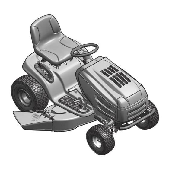
Operator's Manual
Auto Drive
Lawn Tractors
Model 13AR608P731
IMPORTANT: Read safety rules and instructions carefully before operating equipment.
Warning:
This unit is equipped with an internal combustion engine and should not be used on or near any unimproved forest-covered,
brush-covered or grass-covered land unless the engine's exhaust system is equipped with a spark arrester meeting applicable local or state
laws (if any). If a spark arrester is used, it should be maintained in effective working order by the operator. In the State of California the above
is required by law (Section 4442 of the California Public Resources Code). Other states may have similar laws. Federal laws apply on federal
lands. A spark arrester for the muffler is available through your nearest engine authorized service dealer or contact the service department,
P.O. Box 361131 Cleveland, Ohio 44136-0019.
PRINTED IN U.S.A.
FORM NO. 769-01059.fm
(1/2004)
Advertisement
Table of Contents

Related Manuals for MTD 13AR608P731


Summary of Contents for MTD 13AR608P731
- Page 1 Operator’s Manual Auto Drive Lawn Tractors Model 13AR608P731 IMPORTANT: Read safety rules and instructions carefully before operating equipment. Warning: This unit is equipped with an internal combustion engine and should not be used on or near any unimproved forest-covered, brush-covered or grass-covered land unless the engine’s exhaust system is equipped with a spark arrester meeting applicable local or state laws (if any).
-
Page 2: Finding Model Number
This information will be necessary to use the manufacturer’s web site and/or help from the Customer Support Department or an authorized service dealer. Copy the model number here: Copy the serial number here: MTD LLC P. O. BOX 361131 CLEVELAND,OH 44136 330-220-4683 www.mtdproducts.com... -
Page 3: Section 1: Important Safe Operation Practices
SECTION 1: IMPORTANT SAFE OPERATION PRACTICES WARNING: This symbol points out important safety instructions which, if not followed, could endanger the personal safety and/or property of yourself and others. Read and follow all instructions in this manual before attempting to operate this machine. Failure to comply with these instructions may result in personal injury. - Page 4 27. Use only accessories and attachments approved for this Do not tow heavy pull behind attachments (e.g. loaded machine by the machine manufacturer. Read, dump cart, lawn roller, etc.) on slopes greater than 5 understand and follow all instructions provided with the degrees.
-
Page 5: Your Responsibility
Never fill containers inside a vehicle or on a truck serviced professionally by your Troy-Bilt dealer. or trailer bed with a plastic liner. Always place Check brake operation frequently as it is subjected to containers on the ground away from your vehicle wear during normal operation. -
Page 6: Section 2: Slope Gauge
SECTION 2: SLOPE GAUGE... -
Page 7: Section 3: Tractor Set-Up
SECTION 3: TRACTOR SET-UP Attaching the Battery Cables NOTE: If these cables are already connected, skip these four steps and proceed to “Attaching Steering Wheel.” The positive battery terminal is marked Pos. IMPORTANT: (+). The negative battery terminal is marked Neg. (–). 1. -
Page 8: Gas And Oil Fill-Up
WARNING: Before operating this machine, make sure the seat is engaged in the seat stop, stand behind the machine and pull back on seat until fully engaged into stop. Gas and Oil Fill-Up The gasoline tank is located under the hood and depending on the model of tractor, has a capacity of either two or three gallons. -
Page 9: Section 4: Operation
SECTION 4: OPERATION Know the Controls Read this owner’s manual and safety rules before operating your lawn mower. Compare figure below with your lawn tractor to learn about the location and purpose of various controls and adjustments. Save this manual for future reference. - Page 10 NOTE: Any reference in this manual to the RIGHT or LEFT side of the tractor is observed from operator’s position. Throttle Control Lever Choke The throttle control lever controls the speed of the engine. When set in a given position, the throttle will maintain a uniform engine speed. Fast Choke Control Moving the throttle lever all the way forward activates the engine’s choke...
- Page 11 Headlights • To turn on the headlights, rotate the same ignition key from ON position to ON/LIGHTS position of the ignition switch. • To turn off the headlights, rotate the ignition key from ON/LIGHTS position to either ON position (to leave the engine running) or OFF position (to shut the engine off).
-
Page 12: Safety Interlock Switches
NOTE: Cruise control cannot be engaged at the tractor’s fastest ground speed. If the operator should attempt to do so, the tractor will automatically decelerate to the fastest optimal mowing ground speed. • To disengage cruise control, lightly depress either the brake pedal or the drive pedal. •... -
Page 13: Stopping The Engine
Stopping the Engine If you strike a foreign object, stop the WARNING: engine, disconnect the spark plug wire(s) and ground against the engine. Thoroughly inspect the machine for any IMPORTANT damage. Repair damage before restarting. 1. If the blades are engaged, disengage the PTO. 2. -
Page 14: Section 5: Making Adjustments
Mulching Some models are equipped with a mulch kit with special blades to recirculate the grass clippings into the lawn where they act as a natural fertilizer. Observe the following points for best results when mulching. • Never attempt to mulch if the lawn is damp. Wet grass tends to stick to the underside of the cutting deck preventing proper mulching of the clippings. -
Page 15: Leveling The Deck
Leveling the Deck Lock Nut NOTE: Check the tractor’s tire pressure before performing any deck leveling adjustments. Refer to Tires Deck later in this section for details on tire pressure. Stabilizer Bracket Front To Rear Deck The front of the cutting deck is supported by a stabilizer bar that can adjusted to level the deck from front to rear. -
Page 16: Section 6: Maintaining Your Lawn Tractor
SECTION 6: MAINTAINING YOUR LAWN TRACTOR WARNING: Before performing any maintenance or repairs, disengage PTO, move shift lever into neutral position, set parking brake, stop engine and remove key to prevent unintended starting. Engine Refer to the engine manual for engine maintenance instructions. •... -
Page 17: Tire Pressure
WARNING: Before servicing, repairing, or inspecting, always disengage PTO, move shift lever into neutral position, set parking brake, stop engine and remove key from tractor to prevent unintended starting. Tire Pressure Never exceed the maximum inflation pressure shown on the sidewall of the tire. IMPORTANT: •... -
Page 18: Cutting Deck Removal
5. Start the stalled tractor and leave it running to charge the battery. 6. Disconnect the negative (-) jumper cable from the tractor. 7. Disconnect the other end of the negative (-) jumper cable from the negative (-) post of the good battery. 8. -
Page 19: Changing Transmission Drive Belt
Hex Flange Nut Wood Block Blade separation Worn blade edge Wind Wing Sharpen edge evenly Spindle Assembly Figure 11 Each cutting blade edge has to be ground equally to maintain proper blade balance. A poorly balanced IMPORTANT: blade will cause excessive vibration, may damage the tractor and/or result in personal injury. 4. - Page 20 1. Remove the cutting deck as instructed earlier in this section. 2. After disconnecting the battery cables, remove the battery and battery tray from beneath the seat. When removing the battery, disconnect the NEGATIVE (Black) wire from its terminal first, followed by IMPORTANT: the POSITIVE (Red) wire.
- Page 21 After replacing the drive belts, adjust the drive Idler Place wrenches here pedal on your tractor as follows: Adj. Rod 1. Locate the speed control assembly on the underside of the steering support bracket. See Neutral Figure 14. Return 2. Remove both hairpin clips from the pin which is Bracket fastened to the speed control assembly (be careful not to lose the small flat washers found on the pin).
-
Page 22: Off-Season Storage
Carefully allow the ratchet to pivot rearward before removing it from the square hole. IMPORTANT: • Remove the deck belt from around all pulleys and the electric PTO clutch. • Route the new belt as shown in Figure 16. Use 3/8”-drive ratchet wrench to pivot the idler bracket forward and route the belt around the idler pulley. -
Page 23: Section 8: Parts List For Model 608P
SECTION 8: PARTS LIST FOR MODEL 608P Ref. No. Part No. Description 710-0227 AB Screw #8-18 x 0.5 710-0599 TT Screw 1/4-20 x 0.5 710-0726 AB Screw 5/16-12 x 0.75 710-1237 T Screw #10-32 x 0.625 710-1314A Socket Hd. Screw 5/16-18 x 0.75 710-1315 TT Screw 3/8-16 x 1.25 712-0271... - Page 24 Model 608P 70 67...
- Page 25 Model 608P Ref. Part Ref. Part Description Description 683-0195 Bracket Assembly 783-04285 Dash Support Plate RH 710-0599 Self-tapping Screw, 1/4-20 x .5 783-04323 Dash Support Plate LH 747-1184 Hood Plenum Support Rod 710-0751 Hex Cap Screw, 1/4-20 x .62 731-2247A Hood Plenum 710-0924 Phillips Pan Screw, 1/4-20 x .75...
- Page 26 Model 608P...
- Page 27 Model 608P Ref. Part Description Ref. Part Description 747-1130B Deck Stabilizer Rod 783-1489 Seat Mounting Bracket 683-0197B Lift Shaft Assembly 726-0201 Speed Clip 711-0332 Clevis Pin, .5 x .78 783-0209A Seat Lift Bracket 712-0206 Hex Nut, 1/2-13 757-04003 Seat: High Back 712-0431 Flange Lock Nut, 3/8-16 735-0672...
- Page 28 Model 608...
- Page 29 Model 608 Ref. Part Ref. Part Description Description 719-0525C Pivot Bar: Axle 683-04003 LH Axle Assembly, .750 Diameter 710-0604A Self-tapping Screw, 16-18 x .625 683-04004 RH Axle Assembly, .750 Diameter 783-0726B RH Pivot Support Bracket 719-0525C Steel Pivot Bar 783-0727A LH Pivot Support Bracket 712-0130 Lock Nut, 3/8-16...
- Page 30 Model 608 IMPORTANT: For a proper working machine, use Factory Approved Parts. V-belts are designed to engage and disengage safely. A substitute (non OEM) V-belt can be dangerous by not disengaging completely.
- Page 31 Model 608 Ref. Part Ref. Part Description Description 17840 Mounting Bracket 710-1611B TT Screw 5/16-18 x 0.75 618-04133 Drive Assembly 711-04159 618-04147 Variable Spd. Pulley Assembly 712-0130 Hex Lock Nut 3/8-16 647-04020 Shift Lever Assembly 712-3004A Flange Lock Nut 710-0607 TT Screw 5/16-18 x 0.5 714-0104 Cotter Pin...
- Page 32 Model 608 Ref. Part Description 710-3157 Hex Bolt 7/16-20 x 3.25 736-0171 Lock Washer 738-0785 Shoulder Spacer 717-04080 PTO Clutch 754-04033 V Belt 756-0407B Engine Pulley 756-1229 Pulley 710-0859 Hex Bolt 3/8-16 x 2.5 748-0415B Spacer 783-04467 Deck Stop Bracket 710-0726 AB Screw 5/16-12 x 0.75 712-0429...
- Page 33 Model 608 Ref. Part Description 732-0614 Ring, Wire 716-0231 Ring, E Type, .750 736-0336 Flat Washer, 5/8 x 1.0 x .030* 736-0337 Flat Washer, 5/8 x 1.0 x .040* 736-0349 Flat Washer, 5/8 x 1.0 x .020* 736-0335 Washer, Thrust .635 x 1.26 x .06 710-1325 Self-tapping Screw, 1/4-20 x 1.625 719-04017...
- Page 34 Deck: 50-inch 23 29 37 24 18 15...
- Page 35 Deck: 50-inch Ref. Part No. Description Ref. Part No. Description 16606 Retainer Bracket 732-0459 Extension Spring 618-04125 Spindle Assembly 732-0934 Extension Spring 683-0254 Hanger Bracket Assembly LH 734-04039 Deck Wheel 683-04098 Idler Assembly 734-0973 Deck Wheel 683-04120 Deck Assembly w/o Nozzle 736-0119 Lock Washer 5/16 683-04075...
- Page 36 MANUFACTURER’S LIMITED WARRANTY FOR: The limited warranty set forth below is given by MTD LLC with MTD does not extend any warranty for products sold or respect to new merchandise purchased and used in the exported outside of the United States, its possessions United States, its possessions and territories.