
Related Manuals for MTD Bolens 13AP616H565


Summary of Contents for MTD Bolens 13AP616H565
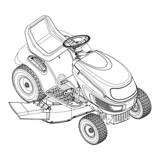
- Page 1 Operator’s Manual Hydrostatic Lawn Tractor IMPORTANT: READ SAFETY RULES AND INSTRUCTIONS CAREFULLY P. O. Box 1386, 97 Kent Ave., KITCHENER, ONTARIO CANADA N2G 4J1 772C0805 (12/05) PRINTED IN UNITED-STATES...
-
Page 2: Table Of Contents
Warranty service is available, WITH PROOF OF PURCHASE, through your local authorized service dealer. To locate the dealer in your area; Contact MTD Products Limited, Kitchener, ON N2G 4J1, or call 1-800-668-1238 or log on to our Web site at www.mtdcanada.com. -
Page 3: Important Safe Operation Practices
SECTION 1: IMPORTANT SAFE OPERATION PRACTICES WARNING: This symbol points out important safety instructions which, if not followed, could endanger the personal safety and/or property of yourself and others. Read and follow all instructions in this manual before attempting to operate this machine. Failure to comply with these instructions may result in personal injury. - Page 4 25. Disengage all attachment clutches, depress the 6. Keep all movement on the slopes slow and gradual. brake pedal completely and shift into neutral before Do not make sudden changes in speed or direction. attempting to start engine. Rapid engagement or braking could cause the front 26.
- Page 5 into reverse. The “Reverse Caution Mode” than ½ inch below bottom of filler neck to should not be used when children or others allow space for fuel expansion. are around. Replace gasoline cap and tighten securely. g. Keep children away from hot or running If gasoline is spilled, wipe it off the engine and engines.
-
Page 6: Safety Labels Found On Your Unit
10. Never attempt to make adjustments or repairs to nal equipment specifications may lead to improper the machine while the engine is running. performance and compromise safety!” 11. Grass catcher components and the discharge 12. Do not change the engine governor settings or cover are subject to wear and damage which could over-speed the engine. - Page 7 SECTION 2: ATTACHMENTS & ACCESSORIES. MODEL DESCRIPTION OEM-190-116 Mulch Kit (For 38” and 42” Decks) OEM-190-118 Mulch Kit (For 46” Decks) OEM-190-180 Twin Bagger Grass Collector 38” and 42” Decks OEM-190-182 Twin Bagger Grass Collector 46” Decks OEM-190-603 FastAttach Grille Guard (mounts on front of tractor) ™...
-
Page 8: Slope Gauge
SECTION 3: SLOPE GAUGE... -
Page 9: Tractor Set-Up
SECTION 4: TRACTOR SET-UP NOTE: ATTACHING THE STEERING WHEEL Reference to RIGHT or LEFT side of the tractor in this manual is observed from operator’s In the event your tractor was crated with the steering position. wheel and the seat removed for shipping reasons, use the following instructions to properly assemble the ATTACHING THE BATTERY CABLES parts. - Page 10 ATTACHING THE SEAT Knob Adjustment Seat styles vary by tractor model and there are two different styles available: Knobs • Quick Adjustment • Knob Adjustment Shoulder Screws Refer to Figure 3 and Figure 4 to identify your tractor’s seat style and follow applicable instructions. Opening in Slot NOTE: For shipping reasons, seats are either...
- Page 11 IDENTIFYING THE MULCH PLUG (if so equipped) On tractor models with 42-inch and 46-inch decks so equipped, a mulch plug can be found within the cutting deck’s discharge opening. NOTE: Refer to '”Mulching“ on page 18 for more detailed information. If you’d prefer to operate the cutting deck without mulching, simply remove the mulch plug by unthreading the plastic wing nut which fastens it to the cutting deck.
-
Page 12: Controls
SECTION 5: CONTROLS NOTE: Steering Wheel not shown for clarity. A* PTO (Power Take-off) Lever (Models with manual PTO) Cruise Control Button PTO (Power Take-off) Knob (Models with electrique PTO) H Ignition Switch Systems Indicator Monitor/Hour Meter Brake Pedal Choke Control Drive Pedal Cup Holder Deck Lift Lever... -
Page 13: Operation
the tractor’s dash panel. This lever controls the speed of IGNITION SWITCH the engine and, on some models, when pushed all the WARNING: Never leave a running machine way forward, the choke control also. When set in a unattended. Always disengage PTO, move given position, the throttle will maintain a uniform engine shift lever into neutral position, set parking speed. - Page 14 Systems Indicator Monitor checked by a authorized dealer. On units so equipped, the ammeter measures the electrical output of the engine’s charging system. Under Located in the center of the tractor’s console, the normal operating conditions, with the engine at full systems indicator monitor records, and displays on its throttle, the ammeter’s needle should measure a LCD, hours of tractor operation whenever the ignition...
- Page 15 CUP HOLDER tractor’s fastest ground speed. If the operator should attempt to do so, the tractor will automatically The tractor’s cup holder is located on the fender to the decelerate to the fastest optimal mowing ground speed. left of the seat, just to the rear of the parking brake lever. PARKING BRAKE BUTTON CRUISE CONTROL...
-
Page 16: Adjustments
Reverse Caution Mode Reverse Push The REVERSE CAUTION MODE position of the key Indicator Button switch module allows the tractor to be operated in Light reverse with the blades (PTO) engaged. Reverse IMPORTANT: Mowing in reverse is not recommended. Caution Mode Stop Position WARNING:... - Page 17 STOPPING THE ENGINE If you strike a foreign object, WARNING: stop the engine, disconnect the spark plug Reverse Forward wire(s) and ground against the engine. Thoroughly inspect the machine for any damage. Repair the damage before restarting Brake Pedal and operating Drive Pedal •...
- Page 18 NOTE: Cruise control cannot be engaged at the Front View Pull Out Push In tractor’s fastest ground speed. If the operator should attempt to do so, the tractor will automatically decelerate to the fastest optimal mowing ground speed. Disengage the cruise control using one of the following methods: •...
- Page 19 • Do not mow at high ground speed, especially if a Carriage Screw mulch kit or grass collector is installed. • For best results it is recommended that the first two laps be cut with the discharge thrown towards the center.
- Page 20 The front of the deck should be between 1/4-inch and • Loosen the jam nut(s) on the rear side of the deck 3/8-inch lower than the rear of the deck. Adjust if stabilizer bracket. See Figure 15A. necessary as follows: •...
- Page 21 Crown Nut Seat Brake Disc Seat Adjustment Lever Figure 16 Hydrostatic Transmission Brake Rod NOTE: View shown from beneath tractor. Knobs Figure 18 STEERING ADJUSTMENT If the tractor turns tighter in one direction than the other, or if the ball joints are being replaced due to damage or wear, the steering drag links may need to be adjusted.
-
Page 22: Maintenance
Front tire toe-in can be measured as follows: • Behind the axle, measure the distance horizontally from the inside of the left rim to the inside of the • Place the steering wheel in position for straight right rim. Note the distance. ahead travel. -
Page 23: Lubrication
Changing Engine Oil dusty condition. To service the air cleaner, refer to the separate engine manual packed with your unit. • Unscrew oil fill cap and remove dipstick from the oil The spark plug(s) should be cleaned and the gap reset fill tube. - Page 24 WARNING: Periodically inspect the blade BATTERY adapter and/or spindle for cracks or damage, The battery is sealed and is maintenance-free. Acid especially if you strike a foreign object. levels cannot be checked. Replace immediately if damaged WARNING: Shield eyes (e.g. goggles, face The blades may be removed as follows.
- Page 25 WARNING: Batteries give off an explosive gas while charging. Charge battery in a well ventilated area and keep away from an open flame or pilot light as on a water heater, space heater, furnace, clothes dryer or other gas appliances. GOOD Figure 24 JUMP STARTING...
- Page 26 • Gently slide the cutting deck toward the front of the • Remove the deck belt(s) from around all pulleys, including the deck idler pulley. tractor allowing the hooks on the deck to release • Route the new belts (deck belt first) as shown in themselves from the deck stabilizer rod.
-
Page 27: Off-Season Storage
Figure 28 SECTION 11: OFF-SEASON STORAGE If the machine is to be inoperative for a period longer WARNING: Use a fuel stabilizer additive or than 30 days, prepare for storage as follows. drain the fuel into an approved container outdoors, away from an open flame. Allow WARNING: Never store the machine or engine to cool. -
Page 28: Troubleshooting
• Clean the engine and the entire unit thoroughly. battery and make sure it has full charge. • Lubricate all lubrication points. Wipe the entire Disconnect the negative terminal of the battery machine with an oiled rag to protect the painted before storing the tractor. -
Page 29: Warranty
How to Obtain Service: Warranty service is available, with proof of purchase, through your local MTD Authorized Service Dealer. If you do not know the dealer in your area, please write to the Service Department of MTD PRODUCTS LIMITED, P.O. BOX 1386, KITCHENER, ONTARIO N2G 4J1. The return of a complete unit will not be accepted by the factory unless prior written permission has been extended by MTD PRODUCTS LIMITED. - Page 30 Style 4/6 Style 4 Style 6 . 3 4 Bolens models only/ Modèles Bolens seulement Style 4 only/ seulement...
- Page 31 PART N° DE N° DE RÉF PIÈCE DE SCRIP TION DE SCRIP TION 710-3015 Hex Cap Bolt 1/4-20 x .75" Lg. Gr. 5 Boulon 1/4-20 x 0,75 po de lg. Qual. 5 710-0599 Hex Wash S-Tapp Scr. 1/4-20 x .50 Vis taraudée 1/4-20 x 0,50 712-04064 Hex L-Flanged Nut 1/4-20 Gr.
- Page 32 Models w/Manually Adjusting Seat Modèles avec siège à réglage manuelle Models w/Quick-Adjust seat Modèles avec siège à réglage facile *Parts for 42” Deck only./Pièces pour plateau de coupe de 42 pouces seulement.
- Page 33 PART N° DE N° DE RÉF PIÈCE DE SCRIP TION DE SCRIP TION 747-1130B Deck Sta bi lizer Rod Tige de sta bili sa tion du pla teau de coupe 683-04079 Lift Shaft As sem bly(42" and 46" Deck) Arbre de relevage (pla teau de coupe de 42 po et 46 po) 683-04118 Lift Shaft As sem bly (54"...
- Page 34 PART N° DE N° DE RÉF PIÈCE DE SCRIP TION DE SCRIP TION 735-0657 LH Foot Pad Pédale gauche 714-0111 Cot ter Pin 3/32 dia. x 1.00 Lg. Goupille fendue 3/32 dia. x 1,00 po de lg. 783-0209D Seat Lift Bracket Sup port de siège 783-04081A Seat Pivot Bracket, Man u ally Ad justed...
- Page 35 (for choke/pour volet) Exhaust gasket, mounting nuts, and starter nut supplied by Kohler/ Le joint d'échappement, les écrous de montage, et l'écrou de démarreur fourni par Kohler. KOHLER V-TWIN PART N° DE N° DE RÉF PIÈCE DE SCRIP TION DE SCRIP TION 710-0227 Hex AB Scr #8-18 x .50 Vis auto-taraudeuse no.
- Page 36 Torque to 400-480 IN-LB/ Serrez à un couple de 400 - 480 po - lb Torque to 130-230 IN-LB/ Serrez à un couple de 130 - 230 po - lb Torque to 400-480 IN-LB/ Serrez à un couple de 400 - 480 po - lb Torque to 150-250 IN-LB/ Serrez à...
- Page 37 710-1260A Hex Wash HD AB Tap Scr 5/16-12 x .75 Vis taraudée 5/16-12 x 0,75 731-04065 Steer ing Wheel Cover - MTD Capuchon de volant - MTD 631-04008A Steer ing Wheel - Soft Grip 3 spoke Volant - poignée mou avec trois rayons...
- Page 38 Detail A Détail A Wheel Chart / Tableau de roue 20 x 8 x 8 20 x 10 x 8 22 32 Square Shoulder Square Shoulder Épaule carré Épaule carré Description Wheel Ass'y Complete/ 634-0177 634-0104 Ensemble de roue complet Attach Spring Tire Only/Roue seulement 734-1730...
- Page 39 PART N° DE N° DE RÉF PIÈCE DE SCRIP TION DE SCRIP TION 17840 Transaxle Mtg. Brkt. Sup port de mon tage de la transessieu 618-0319 Hy dro static Trans mis sion Trans mis sion hydrostatique 629-0949A Re verse Wire Har ness Adapter & Ground Adaptateur, fil de faisceau 783-04442 Dou ble Idler Bracket...
- Page 40 PART N° DE N° DE RÉF PIÈCE DE SCRIP TION DE SCRIP TION 748-04039B Cruise Latch Loquet du régulateur de vitesse 736-3008 Flat Washer .312 ID x .75 OD Rondelle plate 0,312 DI x 0,75 DE 783-04612 Steer ing Sup port Bracket Sup port de di rec tion 783-0663E Drive Lock out Bracket...
- Page 41 KOHLER SINGLE PART N° DE N° DE RÉF PIÈCE DE SCRIP TION DE SCRIP TION 710-0227 Hex AB Scr #8-18 x .50 Vis auto-taraudeuse no. 8-18 x 0,50 710-0599 Hex Wash S-Tapp Scr 1/4-20 x .50 Vis autotaraudeuse à rondelle hex. de 1/4-20 x 0,5 710-0726 Hex Wash HD AB Tap Scr 5/16 x .75 Vis taraudée 5/16 x 0,75...
- Page 42 � � � Ground Wire Ref. Only/ Fil masse comme référence seulement. 42-inch Deck Plateau 46 and 54 de coupe inch Deck � de 42 po †31 Plateau de coupe de 46 et 54 po * 46” Hydrostatic models only./Modèles hydrostatique de 46 po seulement. †...
- Page 43 REF. PART N°. DE N° DE RÉF. PIÈCE DESCRIPTION DESCRIPTION 683-04173 Lower Frame Assembly Châssis inférieur 710-0607 Hex Wash HD S-Tapp Scr 5/16-18 x .50 Vis auto-taraudeuse hexagonal 5/16-18 x 0,50 710-0642 Thd Forming Scr. 1/4-20 x .75 Lg. Vis taraudée 1/4-20 x 0,75 lg. 710-0726 Hex Wash HD AB Tap Scr 5/16 x .75 Vis taraudée 5/16 x 0,75...
- Page 44 42-inch Deck Plateau de coupe 42 po...
- Page 45 PART N° DE N° DE RÉF PIÈCE DE SCRIP TION DE SCRIP TION 618-0624 Spin dle As sem bly 6.3 dia. Fu sée dia. de 6,30 683-04138A Deck Brake As sem bly Frein du pla teau de coupe 783-04491 Pivot Idler Bracket Sup port de tendeur de pivot 683-04261 42"...
- Page 46 46-inch Deck Plateau de coupe 46 po †12 †50 †5 †63 †58 †53 †21 †61 †48 †46 †65 †49 †55 †67 †66 †59 †47 †54 †60 23 6 †45 2 18 †57 †12 †47 †62 †64 †55 710-0751 Torque to 50-150 FT-LBS/ †68 Serrez à...
- Page 47 PART N° DE N° DE RÉF PIÈCE DE SCRIP TION DE SCRIP TION 618-0625 Spin dle Ass’y 5.75 Dia w/grease fit ting Fu sée diamètre de 5,75 avec graisseur 683-0254B Deck Ad just ment Bracket w/Weld Nut Supp. de réglage du pla teau de coupe à écrou soudé 683-04104A 46"...
- Page 48 PART N° DE N° DE RÉF PIÈCE DE SCRIP TION DE SCRIP TION 748-0234 Shoul der Spacer .25 THK Entretoise épaulée 750-0566A Spacer .260 x .375 x 1.030 Lg. Entretoise 0,260 x 0,375 x 1,030 lg. 750-1320 Spacer .375 x .63 x .595 Entretoise 0,375 x 0,63 x 0,595 754-0349 V-Belt...
- Page 49 notes . . .