Table of Contents
Advertisement
Quick Links
Register at www.Toro.com.
Original Instructions (EN)
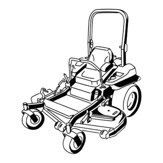
Z Master
®
Series Riding Mower
with 48in, 52in, or 60in TURBO FORCE
Discharge Mower
Model No. 74141—Serial No. 313000001 and Up
Model No. 74143—Serial No. 313000001 and Up
Model No. 74145—Serial No. 313000001 and Up
Form No. 3375-549 Rev B
Commercial 2000
®
Side
*3375-549* B
Advertisement
Table of Contents

Related Manuals for Toro 74143


Summary of Contents for Toro 74143
- Page 1 48in, 52in, or 60in TURBO FORCE ® Side Discharge Mower Model No. 74141—Serial No. 313000001 and Up Model No. 74143—Serial No. 313000001 and Up Model No. 74145—Serial No. 313000001 and Up *3375-549* B Register at www.Toro.com. Original Instructions (EN)
- Page 2 If you require a spark arrestor, contact your Authorized Toro Dealer. Genuine Toro spark arresters are approved by the USDA Forestry Service. Note: It is a violation of California Public Resource...
-
Page 3: Introduction
You are responsible for operating the attention. product properly and safely. You may contact Toro directly at www.Toro.com for product and accessory information, help finding a dealer, or to register your product. Whenever you need service, genuine Toro parts, or additional... -
Page 4: Table Of Contents
Contents Checking the Wheel Lug Nuts ........39 Adjusting the Caster Pivot Bearing ......39 Adjusting the Electric Clutch........39 Introduction ..............3 Cooling System Maintenance ........40 Safety ................5 Cleaning the Engine Screen........40 Safe Operating Practices........... 5 Cleaning the Engine Cooling Fins and Slope Indicator ............ -
Page 5: Safety
Safety – Never remove gas cap or add fuel with engine running. Allow engine to cool before refueling. Do not smoke. Improper use or maintenance by the operator or owner can • Check that operator's presence controls, safety switches result in injury. To reduce the potential for injury, comply with and shields are attached and functioning properly. - Page 6 Replace all worn or damaged decals. These can change the stability of the machine and cause loss of control. • Use only Toro approved attachments. Warranty may be voided if used with unapproved attachments. Using the Rollover Protection System (ROPS) •...
-
Page 7: Slope Indicator
Slope Indicator G011841 Figure 3 This page may be copied for personal use. 1. The maximum slope you can safely operate the machine on is 15 degrees. Use the slope chart to determine the degree of slope of hills before operating. Do not operate this machine on a slope greater than 15 degrees. Fold along the appropriate line to match the recommended slope. -
Page 8: Safety And Instructional Decals
Safety and Instructional Decals Safety decals and instructions are easily visible to the operator and are located near any area of potential danger. Replace any decal that is damaged or lost. 68-8340 1-403005 98-5954 103-2076 54-9220 Manufacturer's Mark 1. Indicates the blade is identified as a part from the original machine manufacturer. - Page 9 116-0205 109-7232 116-1654 112-3858 1. Read the Operator's 3. Remove the ignition key Manual. before adjusting the height of cut. 2. Read the instructions 4. Height of cut settings. before servicing or performing maintenance. 116-3303 114-4466 1. Main, 25A 3. Charge, 25A 2.
- Page 10 119-2501 116-5944 1. Choke 3. Slow 2. Fast 4. PTO (Power Take-off) 117–1158 1. Bypass lever position for 2. Bypass lever position for operating the machine. pushing the machine. 120-2522 117-8639 1. Belt routing 2. Grease pulley, maintenance interval—50 hours 120-2532...
- Page 11 121–3223 Battery Symbols Some or all of these symbols are on your battery 1. Explosion hazard 6. Keep bystandersa safe distance from the battery. 2. No fire, open flame, or 7. Wear eye protection; smoking. explosive gases can cause blindness and other injuries 107-2102 3.
-
Page 12: Product Overview
A selection of Toro approved attachments and accessories is available for use with the machine to enhance and expand its capabilities. Contact your Authorized Service Dealer or Distributor or go to www.Toro.com for a list of all approved attachments and accessories. G017418 Figure 5 4. -
Page 13: Specifications
Weight 74141 926 lb (420 kg) • Fill the fuel tank outdoors on level ground, in an open area, when the engine is cold. Wipe up 74143 944 lb (428 kg) any gasoline that spills. 74145 988 lb (448 kg) •... -
Page 14: Checking The Engine Oil Level
Filling the Fuel Tank DANGER Note: Do not fill the fuel tank completely full. Fill the fuel In certain conditions during fueling, static tank to the bottom of the filler neck. The empty space in the electricity can be released causing a spark which tank allows the gasoline to expand. -
Page 15: Breaking In A New Machine
Breaking In a New Machine New engines take time to develop full power. Mower decks and drive systems have higher friction when new, placing additional load on the engine. Allow 40 to 50 hours of break-in time for new machines to develop full power and best performance. -
Page 16: Operating The Parking Brake
The use of protective equipment for eyes, ears, feet and head DANGER is recommended. Operating on wet grass or steep slopes can cause sliding and loss of control. Wheels dropping over edges can cause rollovers, which may result in serious injury, death or drowning. -
Page 17: Operating The Mower Blade Control Switch (Pto)
Operating the Mower Blade Operating the Choke Control Switch (PTO) Use the choke to start a cold engine. 1. If the engine is cold, use the choke to start the engine. The blade control switch (PTO) starts and stops the mower blades and any powered attachments. -
Page 18: Operating The Ignition Switch
Operating the Ignition Switch 1. Turn the ignition key to the Start position (Figure 16). When the engines starts, release the key. Important: Do not engage starter for more than 5 seconds at a time. If the engine fails to start allow a 15 second cool-down period between attempts. - Page 19 Stopping the Engine CAUTION Children or bystanders may be injured if they move or attempt to operate the machine while it is unattended. Always remove the ignition key and set the parking brake when leaving the machine unattended, even if just for a few minutes. Let the engine idle at slow throttle (turtle) for 60 seconds before turning the ignition switch off.
-
Page 20: The Safety Interlock System
The Safety Interlock System motion control levers to neutral lock position. Try starting the engine; the engine should not crank. CAUTION Driving Forward or Backward If safety interlock switches are disconnected or damaged the machine could operate unexpectedly The throttle control regulates the engine speed as measured causing personal injury. -
Page 21: Stopping The Machine
To stop, pull the motion control levers to the neutral position. 1. Release the parking brake; refer to Releasing the Parking Brake in Operation. 2. Move the levers to the center, unlocked position. 3. To go forward, slowly push the motion control levers forward (Figure 22). -
Page 22: Adjusting The Anti-Scalp Rollers
Adjusting the Height-of-Cut Pin Mower deck size Height-of-cut range Increments 48 inch 1-1/2 to 5 inches 1/4 inch (6 mm) (38 to 127 mm) 52 inch and 60 inch 1-1/2 to 5-1/2 1/4 inch (6 mm) inches (38 to 140 The height-of-cut is adjusted by relocating the clevis pin into different hole locations. -
Page 23: Positioning The Seat
Using the Drive Wheel Release Valves WARNING Hands may become entangled in the rotating drive components below the engine deck, which could result in serious injury. Stop the engine, remove the key, and allow all moving parts to stop before accessing the drive g017628 wheel release valves. -
Page 24: Using The Side Discharge
5. To run the machine, move the bypass levers to the WARNING forward position (Figure 29). Loading a unit onto a trailer or truck increases the possibility of backward tip-over and could cause Using the Side Discharge serious injury or death. •... -
Page 25: Operating Tips
Cutting a Lawn for the First Time all the safety instructions. Knowing this information could help you, your family, pets or bystanders avoid injury. Cut grass slightly longer than normal to ensure the cutting height of the mower does not scalp any uneven ground. WARNING However, the cutting height used in the past is generally the best one to use. - Page 26 Check the cutter blades daily for sharpness, and for any wear or damage. File down any nicks and sharpen the blades as necessary. If a blade is damaged or worn, replace it immediately with a genuine TORO replacement blade.
-
Page 27: Maintenance
Maintenance Recommended Maintenance Schedule(s) Maintenance Service Maintenance Procedure Interval • Change the engine oil. After the first 8 hours • Check the torque on the wheel lug nuts. • Change the hydraulic system filter and oil. After the first 50 hours •... -
Page 28: Lubrication
Lubrication Where to Grease the Mower Service Interval: Every 50 hours—Grease the mower deck idler arm. Greasing and Lubrication Yearly—Grease the front caster pivots (more often in Grease more frequently when operating conditions are dirty or dusty conditions). extremely dusty or sandy. 1. -
Page 29: Lubricate The Caster Wheel Hubs
Lubricate the Caster Wheel Reinstall the seal guards over the wheel hub and insert wheel into caster fork. Reinstall caster bolt and tighten Hubs nut fully. Service Interval: Yearly—Lubricate the caster wheel hubs Important: To prevent seal and bearing damage, check (more often in dirty or dusty conditions). -
Page 30: Engine Maintenance
Engine Maintenance WARNING Contact with hot surfaces may cause personal injury. Keep hands, feet, face, clothing and other body parts away the muffler and other hot surfaces. Servicing the Air Cleaner Service Interval: Every 250 hours—Replace the primary air filter. Figure 36 Every 250 hours—Check the secondary air filter. -
Page 31: Servicing The Engine Oil
Servicing the Engine Oil Oil Type: Detergent oil (API service SF, SG, SH, SJ, or SL) Crankcase Capacity: with a filter change, 71 ounces (2.1 L); without a filter change, 61 ounces (1.8 L) Viscosity: See the table below. G008804 Figure 37 Note: Use of multi-grade oils (5W-20, 10W-30, or 10W-40) will increase oil consumption. - Page 32 Changing the Engine Oil 5. Slowly pour approximately 80% of the specified oil into the filler tube and slowly add the additional oil to Service Interval: After the first 8 hours bring it to the Full mark (Figure 40). Every 100 hours (more often in dirty or dusty conditions) Note: Dispose of the used oil at a recycling center.
-
Page 33: Servicing The Spark Plug
Servicing the Spark Plug Service Interval: Every 100 hours Make sure the air gap between the center and side electrodes is correct before installing the spark plug. Use a spark plug wrench for removing and installing the spark plug(s) and a G008804 gapping tool/feeler gauge to check and adjust the air gap. -
Page 34: Check Spark Arrester (If Equipped)
Check Spark Arrester (if equipped) Service Interval: Every 50 hours WARNING Hot exhaust system components may ignite G008794 gasoline vapors even after the engine is stopped. Figure 43 Hot particles exhausted during engine operation may ignite flammable materials. Fire may result in personal injury or property damage. -
Page 35: Fuel System Maintenance
Servicing the Fuel Tank Fuel System Maintenance Do not attempt to drain the fuel tank. Ensure that an Authorized Service Dealer drains the fuel tank and services any components of the fuel system. Replacing the Fuel Filter Service Interval: Every 500 hours/Yearly (whichever comes first) (more often in dirty or dusty conditions). -
Page 36: Electrical System Maintenance
Electrical System WARNING Maintenance Incorrect battery cable routing could damage the machine and cables causing sparks. Sparks can cause the battery gasses to explode, resulting in Servicing the Battery personal injury. • Always Disconnect the negative (black) battery Service Interval: Monthly cable before disconnecting the positive (red) cable. -
Page 37: Servicing The Fuses
Installing the Battery 1. Position battery in the tray with the terminal posts opposite from the hydraulic tank (Figure 46). 2. First, install the positive (red) battery cable to positive (+) battery terminal. 3. Then install the negative (black) battery cable and ground wire to the negative (-) battery terminal. -
Page 38: Drive System Maintenance
Drive System Maintenance Checking the Seat Belt Service Interval: Before each use or daily Visually inspect seat belt for wear, cuts, and proper operation of retractor and buckle. Replace before operating if damaged. Checking the Rollover Protection System (ROPS) Knobs Service Interval: Before each use or daily WARNING To avoid injury or death from rollover: keep the roll... -
Page 39: Checking The Tire Pressure
Checking the Wheel Lug Nuts Service Interval: After the first 8 hours Yearly Check and torque the wheel lug nuts to 90-100 ft-lb (122-136 N-m). Adjusting the Caster Pivot Bearing Service Interval: Every 500 hours/Yearly (whichever comes first) 1. Disengage the blade control switch (PTO), move the motion control levers to the neutral locked position and set the parking brake. -
Page 40: Cooling System Maintenance
Cooling System The clutch is adjustable to ensure proper engagement and proper braking. Maintenance 1. Insert a 0.015–0.021 inch (0.381–0.533 mm) feeler gauge through one inspection slot in the side of the assembly. Make sure it is between the armature and Cleaning the Engine Screen the rotor friction surfaces. -
Page 41: Belt Maintenance
Belt Maintenance Inspecting the Belts Service Interval: Every 50 hours Check the belts for squealing when the belt is rotating, blades slipping when cutting grass, frayed belt edges, burn marks and cracks are signs of a worn mower belt. Replace the mower belt if any of these conditions are evident. -
Page 42: Replacing The Hydraulic Pump Drive Belt
8. Install the new belt around the engine pulley and the two drive pulleys. Figure 57 g017437 1. Position the belt cover 3. Ensure the tab is under the metal catch Figure 59 2. Slide belt cover under the 1. Idler pulley 4. -
Page 43: Controls System Maintenance
Controls System Maintenance Adjusting the Control Handle Position There are two height positions for the control levers; high and low. Remove the bolts to adjust the height for the operator. 1. Disengage the PTO, move the motion control levers to the neutral locked position, and set the parking brake. - Page 44 7. Slide the seat and seat plate forward to allow the front 13. Start engine. Brake must be engaged and motion nuts to go through the key hole (Figure 62). control levers out to start engine. Operator does not have to be in the seat because of the jumper wire being used.
-
Page 45: Adjusting The Motion Control Damper
Adjusting the Motion Control Damper The top damper mounting bolt can be adjusted to obtain a more desired motion control lever resistance. See Figure 65 for mounting options. Figure 66 1. Flanged nut 2. Jam nut Figure 65 RH Motion Control Shown 1. -
Page 46: Hydraulic System Maintenance
Service Interval: Every 25 hours 1. Allow the hydraulic oil to cool down. Check the oil level when the oil is cold. ® 2. Check expansion reservoir and if necessary add Toro ™ HYPR-OIL 500 hydraulic oil to the FULL COLD line. - Page 47 Bleeding the Hydraulic System 1. Raise the rear of machine up and support with jack stands (or equivalent support) just high enough to allow drive wheels to turn freely. g017625 Figure 70 1. Jacking points 2. Enter the operator's position. Start engine and move throttle control ahead to 1/2 throttle position.
-
Page 48: Mower Deck Maintenance
Mower Deck 6. Insert the height adjustment pin into the 3 inch (7.6 cm) cutting height location. Maintenance 7. Release the transport lock and allow the deck to lower to the cutting height. Leveling the Mower Deck 8. Raise the discharge chute. 9. - Page 49 bolts at least 1/3 the length of the available travel in their slots. This will regain some up and down adjustment on each of the four deck links. g017036 Figure 75 g017441 1. Single point adjustment bolt Figure 73 1. Whizlock nut 3.
-
Page 50: Servicing The Cutting Blades
If a blade is damaged or worn, replace the cutting edge, position A, of the blades (Figure 77). it immediately with a genuine Toro replacement blade. For Note this dimension. convenient sharpening and replacement, you may want to keep extra blades on hand. - Page 51 by other manufacturers may result in non-conformance with position, the blade is balanced and can be used. If the safety standards. blade is not balanced, file some metal off the end of the sail area only (Figure 81). Repeat this procedure 1.
-
Page 52: Removing The Mower Deck
Installing the Blades Removing the Mower Deck Important: The curved part of the blade must be Before servicing or removing the mower deck, the spring pointing upward toward the inside of the mower to loaded deck arms must be locked out. ensure proper cutting. -
Page 53: Replacing The Grass Deflector
g015594 Figure 84 1. Bolt 5. Spring installed 2. Spacer 6. Grass Deflector 3. Locknut 7. J hook end of spring g017417 4. Spring Figure 83 2. Place spacer and spring onto grass deflector. Place one 1. Remove the rear deck lift attachment shoulder bolt and nut. J end of spring behind deck edge. -
Page 54: Cleaning
Cleaning Storage Cleaning and Storage Cleaning Under the Mower 1. Disengage the power take off (blade control switch Service Interval: Before each use or daily (PTO), set the parking brake, and turn the ignition key to Off. Remove the key. 1. - Page 55 C. Stop the engine, allow it to cool, and drain the fuel tank; refer to Servicing the Fuel Tank in the Maintenance Section. D. Restart the engine and run it until it stops. E. Dispose of fuel properly. Recycle as per local codes.
-
Page 56: Troubleshooting
Troubleshooting Problem Possible Cause Corrective Action Starter does not crank 1. Blade control switch (PTO) is engaged. 1. Move blade control switch (PTO) to disengaged. 2. Parking brake is not on. 2. Set the parking brake. 3. Drive levers are not in neutral lock 3. - Page 57 Problem Possible Cause Corrective Action Machine does not drive. 1. By pass valves is not closed tight. 1. Tighten the by pass valves. 2. Pump belt is worn, loose or broken. 2. Change the belt. 3. Pump belt is off a pulley. 3.
-
Page 58: Schematics
Schematics g018479 Wire Diagram (Rev. A) - Page 59 Notes:...
- Page 60 Customers who have purchased Toro products outside the United States or Canada should contact their Toro Distributor (Dealer) to obtain guarantee policies for your country, province, or state. If for any reason you are dissatisfied with your Distributor's service or have difficulty obtaining guarantee information, contact the Toro importer. If all other remedies fail, you may contact us at Toro Warranty Company.