Table of Contents
Advertisement
Form No. 3372-548 Rev C
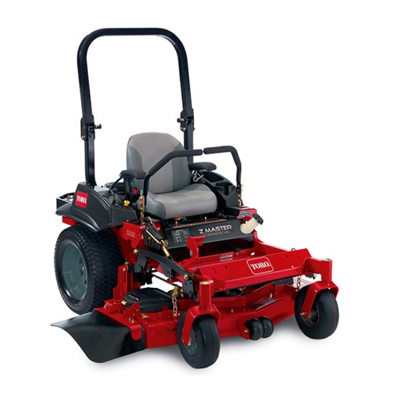
Z Master
®
Riding Mower
with 48in, 52in or 60in TURBO FORCE
®
Side
Discharge Mower
Model No. 74141—Serial No. 312000001 and Up
Model No. 74143—Serial No. 312000001 and Up
Model No. 74145—Serial No. 312000001 and Up
To register your product or download an Operator's Manual or Parts Catalog at no charge, go to www.Toro.com.
Original Instructions (EN)
Advertisement
Table of Contents

Related Manuals for Toro Z Master 74141


Summary of Contents for Toro Z Master 74141
- Page 1 Model No. 74141—Serial No. 312000001 and Up Model No. 74143—Serial No. 312000001 and Up Model No. 74145—Serial No. 312000001 and Up To register your product or download an Operator's Manual or Parts Catalog at no charge, go to www.Toro.com. Original Instructions (EN)
-
Page 2: Figure 1
Figure 1 identifies the location of the model and serial Authorized Toro Dealer. numbers on the product. Write the numbers in the Genuine Toro spark arresters are approved by the USDA space provided. Forestry Service. Note: It is a violation of California Public Resource... -
Page 3: Table Of Contents
Lubricate the Caster Wheel Hubs......29 Engine Maintenance..........30 Servicing the Air Cleaner ........30 Figure 2 Servicing the Engine Oil ........31 Servicing the Spark Plug ........33 1. Safety alert symbol Check Spark Arrester (if equipped)...... 34 Fuel System Maintenance ........35 This manual uses 2 other words to highlight information. -
Page 4: Safety
Safety • Use extra care when handling gasoline and other fuels. They are flammable and vapors are explosive. Improper use or maintenance by the operator or owner – Use only an approved container can result in injury. To reduce the potential for injury, –... -
Page 5: Slope Operation
• Be aware of the mower discharge direction and do • Be certain that the seat belt can be released quickly not point it at anyone. in the event of an emergency. • Do not operate the mower under the influence of •... - Page 6 • Keep all parts in good working condition and all hardware tightened. Replace all worn or damaged decals. • Use only Toro approved attachments. Warranty may be voided if used with unapproved attachments.
-
Page 7: Slope Indicator
Slope Indicator G011841 Figure 3 This page may be copied for personal use. 1. The maximum slope you can safely operate the machine on is 15 degrees. Use the slope chart to determine the degree of slope of hills before operating. Do not operate this machine on a slope greater than 15 degrees. Fold along the appropriate line to match the recommended slope. -
Page 8: Safety And Instructional Decals
Safety and Instructional Decals Safety decals and instructions are easily visible to the operator and are located near any area of potential danger. Replace any decal that is damaged or lost. 68-8340 1-403005 98-5954 103-2076 54-9220 58-6520 1. Grease 66-1340... - Page 9 112-3858 1. Read the Operator's 3. Remove the ignition key Manual. before adjusting the height of cut. 2. Read the instructions 4. Height of cut settings. before servicing or performing maintenance. 114-4466 1. Main, 25A 3. Charge, 25A 2. PTO, 10A 4.
- Page 10 116-3303 117–1158 1. Bypass lever position for 2. Bypass lever position for operating the machine. pushing the machine. 116-4858 117-8639 1. Belt routing 2. Grease pulley, maintenance interval—50 hours 116-5988 1. Parking brake—engaged 2. Parking brake—disengaged 119-2501 1. Choke 3. Slow 2.
- Page 11 121–3223 120-2522 Battery Symbols Some or all of these symbols are on your battery 1. Explosion hazard 6. Keep bystandersa safe distance from the battery. 2. No fire, open flame, or 7. Wear eye protection; smoking. explosive gases can cause blindness and other injuries 3.
-
Page 12: Product Overview
5. Ignition switch Authorized Service Dealer or Distributor or go to 3. Throttle control 6. Fuses www.Toro.com for a list of all approved attachments and accessories. Hour Meter The hour meter records the number of hours the engine has operated. It operates when the engine is running. -
Page 13: Specifications
Specifications Operation Note: Specifications and design are subject to change Note: Determine the left and right sides of the without notice. machine from the normal operating position. Width: Adding Fuel 48 inch Deck 52 inch Deck 60 inch Deck Without Deck 45.3 inches 47.0 inches 50.5 inches... -
Page 14: Filling The Fuel Tank
Note: A fuel stabilizer/conditioner is most effective DANGER when mixed with fresh gasoline. To minimize the In certain conditions during fueling, static chance of varnish deposits in the fuel system, use fuel electricity can be released causing a spark which stabilizer at all times. -
Page 15: Checking The Engine Oil Level
Checking the Engine Oil Level Before you start the engine and use the machine, check the oil level in the engine crankcase; refer to Checking the Engine Oil Level. Breaking In a New Machine New engines take time to develop full power. Mower decks and drive systems have higher friction when new, placing additional load on the engine. -
Page 16: Operating The Parking Brake
DANGER CAUTION Operating on wet grass or steep slopes can cause This machine produces sound levels in excess of sliding and loss of control. 85 dBA at the operators ear and can cause hearing loss through extended periods of exposure. Wheels dropping over edges can cause rollovers, which may result in serious injury, death or Wear hearing protection when operating this... -
Page 17: Operating The Mower Blade Control Switch (Pto)
Releasing the Parking Brake Operating the Throttle The throttle control can be moved between Fast and Slow positions (Figure 14). Always use the fast position when turning on the mower deck with the blade control switch (PTO). G017427 Figure 11 G008946 Operating the Mower Blade Figure 14... -
Page 18: Operating The Ignition Switch
Operating the Ignition Switch 1. Turn the ignition key to the Start position (Figure 16). When the engines starts, release the key. Important: Do not engage starter for more than 5 seconds at a time. If the engine fails to start allow a 15 second cool-down period G017428 between attempts. -
Page 19: Stopping The Engine
Stopping the Engine CAUTION Children or bystanders may be injured if they move or attempt to operate the tractor while it is unattended. Always remove the ignition key and set the parking brake when leaving the machine unattended, even if just for a few minutes. Let the engine idle at slow throttle (turtle) for 60 seconds before turning the ignition switch off. -
Page 20: The Safety Interlock System
The Safety Interlock System the motion control levers to neutral lock position. Now start the engine. While the engine is running, center either motion control and move (forward or CAUTION reverse); the engine should stop. Repeat for other If safety interlock switches are disconnected or motion control. - Page 21 Using the Motion Control Levers G008952 Figure 22 Figure 21 Driving Backward 1. Motion control 4. Backward 1. Move the levers to the center, unlocked position. lever-neutral lock position 2. To go backward, slowly pull the motion control 2. Center, unlocked position 5.
-
Page 22: Stopping The Machine
Stopping the Machine To stop the machine, move the traction control levers to neutral and move to locked position, disengage the power take off (blade control switch (PTO), and turn the ignition key to off. Set the parking brake when you leave the machine; refer to Setting the Parking Brake in Operation. -
Page 23: Adjusting The Anti-Scalp Rollers
Adjusting the Height-of-Cut Pin 1. Disengage the blade control switch (PTO), move the motion control levers to the neutral locked Mower deck size Height-of-cut range Increments position and set the parking brake. 48 inch 1-1/2 to 5 inches 1/4 inch (6 mm) 2. -
Page 24: Using The Drive Wheel Release Valves
G008962 Figure 28 Using the Drive Wheel Release Valves g017420 WARNING Figure 29 Hands may become entangled in the rotating drive components below the engine deck, which could 5. To run the machine, move the bypass levers to the result in serious injury. forward position (Figure 29). -
Page 25: Transporting Machines
individual ramps for each side of the unit (Figure 30). The lower rear section of the tractor frame extends back between the rear wheels and serves as a stop for tipping backward. Having a full width ramp provides a surface for the frame members to contact if the unit starts to tip backward. -
Page 26: Operating Tips
Alternate mowing direction to keep the grass standing down any nicks and sharpen the blades as necessary. If straight. This also helps disperse clippings which a blade is damaged or worn, replace it immediately with enhances decomposition and fertilization. a genuine TORO replacement blade. -
Page 27: Maintenance
Maintenance Recommended Maintenance Schedule(s) Maintenance Service Maintenance Procedure Interval • Change the engine oil. After the first 8 hours • Change the hydraulic system filter and oil. After the first 50 hours • Check the safety system. • Check the engine oil level. •... -
Page 28: Lubrication
Lubrication Where to Grease the Mower Service Interval: Every 50 hours—Grease the mower Greasing and Lubrication deck idler arm. Yearly—Grease the front caster Grease more frequently when operating conditions are pivots (more often in dirty or dusty extremely dusty or sandy. conditions). -
Page 29: Lubricate The Caster Wheel Hubs
8. If the axle assembly has had both spacer nuts removed (or broken loose), apply a thread locking adhesive to one spacer nut and thread onto the axle with the wrench flats facing outward. Do Not thread spacer nut all of the way onto the end of the axle. Leave approximately 1/8 inch (3 mm) from the outer surface of the spacer nut to the end of the axle inside the nut. -
Page 30: Engine Maintenance
Engine Maintenance WARNING Contact with hot surfaces may cause personal injury. Keep hands, feet, face, clothing and other body parts away the muffler and other hot surfaces. Servicing the Air Cleaner Service Interval: Every 250 hours—Replace the primary air filter. Figure 36 Every 250 hours—Check the 1. -
Page 31: Servicing The Engine Oil
Servicing the Engine Oil Oil Type: Detergent oil (API service SF, SG, SH, SJ, or SL) Crankcase Capacity: with a filter change, 71 ounces (2.1 L); without a filter change, 61 ounces (1.8 L) G008804 Viscosity: See the table below. Figure 37 Note: Use of multi-grade oils (5W-20, 10W-30, or 10W-40) will increase oil consumption. -
Page 32: Changing The Engine Oil
Changing the Engine Oil 5. Slowly pour approximately 80% of the specified oil into the filler tube and slowly add the additional oil Service Interval: After the first 8 hours to bring it to the Full mark (Figure 40). Every 100 hours (more often in dirty or dusty conditions) Note: Dispose of the used oil at a recycling center. -
Page 33: Servicing The Spark Plug
Servicing the Spark Plug Service Interval: Every 100 hours Make sure the air gap between the center and side electrodes is correct before installing the spark plug. Use a spark plug wrench for removing and installing G008804 the spark plug(s) and a gapping tool/feeler gauge to check and adjust the air gap. -
Page 34: Check Spark Arrester (If Equipped)
Check Spark Arrester (if equipped) Service Interval: Every 50 hours WARNING Hot exhaust system components may ignite G008794 gasoline vapors even after the engine is stopped. Figure 43 Hot particles exhausted during engine operation may ignite flammable materials. Fire may result in personal injury or property damage. -
Page 35: Fuel System Maintenance
Fuel System Note: It is important to reinstall the fuel line hoses and secure with plastic ties the same as they were originally Maintenance installed at the factory to keep the fuel line away from components that could cause fuel line damage. Replacing the Fuel Filter Servicing the Fuel Tank Service Interval: Every 500 hours/Yearly (whichever... -
Page 36: Electrical System Maintenance
Electrical System WARNING Maintenance Incorrect battery cable routing could damage the machine and cables causing sparks. Sparks can cause the battery gasses to explode, resulting in Servicing the Battery personal injury. • Always Disconnect the negative (black) battery Service Interval: Monthly cable before disconnecting the positive (red) cable. -
Page 37: Servicing The Fuses
Installing the Battery 1. Position battery in the tray with the terminal posts opposite from the hydraulic tank (Figure 46). 2. First, install the positive (red) battery cable to positive (+) battery terminal. 3. Then install the negative (black) battery cable and ground wire to the negative (-) battery terminal. -
Page 38: Drive System Maintenance
Drive System Maintenance Checking the Seat Belt Service Interval: Before each use or daily Visually inspect seat belt for wear, cuts, and proper operation of retractor and buckle. Replace before operating if damaged. Checking the Rollover Protection System (ROPS) Knobs Service Interval: Before each use or daily WARNING To avoid injury or death from rollover: keep the roll... -
Page 39: Checking The Tire Pressure
7. If it tracks to the left, loosen the bolts and adjust the right stop plate rearward on the right T-slot until the machine tracks straight (Figure 50). 8. Tighten the stop plate (Figure 50). Figure 51 Adjusting the Caster Pivot Bearing Service Interval: Every 500 hours/Yearly (whichever comes first) -
Page 40: Adjusting The Electric Clutch
Figure 53 1. Adjusting nut 3. Feeler gauge 2. Slot Figure 52 1. Spring Washers 3. Dust Cap 2. Lock Nut Adjusting the Electric Clutch Service Interval: Every 500 hours—Check the electric clutch. The clutch is adjustable to ensure proper engagement and proper braking. -
Page 41: Cooling System Maintenance
Cooling System Maintenance Cleaning the Engine Screen Service Interval: Before each use or daily Before each use remove any build-up of grass, dirt or other debris from the engine screen. This will help insure adequate cooling and correct engine speed and will reduce the possibility of overheating and mechanical damage to the engine (Figure 54). -
Page 42: Belt Maintenance
Belt Maintenance Inspecting the Belts Service Interval: Every 50 hours Check the belts for squealing when the belt is rotating, blades slipping when cutting grass, frayed belt edges, burn marks and cracks are signs of a worn mower belt. Replace the mower belt if any of these conditions are evident. -
Page 43: Replacing The Hydraulic Pump Drive Belt
8. Install the new belt around the engine pulley and the two drive pulleys. Figure 57 g017437 1. Position the belt cover 3. Ensure the tab is under the metal catch Figure 59 2. Slide belt cover under the 1. Idler pulley 4. -
Page 44: Controls System Maintenance
Controls System Maintenance Adjusting the Control Handle Position There are two height positions for the control levers; high and low. Remove the bolts to adjust the height for the operator. 1. Disengage the PTO, move the motion control levers to the neutral locked position, and set the parking brake. - Page 45 7. Slide the seat and seat plate forward to allow the 12. Temporarily install a jumper wire across the front nuts to go through the key hole (Figure 62). terminals in the connector of the main wiring harness. 13. Start engine. Brake must be engaged and motion control levers out to start engine.
-
Page 46: Adjusting The Motion Control Damper
Adjusting the Motion Control Damper The top damper mounting bolt can be adjusted to obtain a more desired motion control lever resistance. See Figure 65 for mounting options. Figure 66 1. Flanged nut 2. Jam nut Figure 65 RH Motion Control Shown 1. -
Page 47: Hydraulic System Maintenance
Removing Hydraulic System Filters Servicing the Hydraulic 1. Stop engine, wait for all moving parts to stop, and System allow engine to cool. Remove the key and engage Hydraulic Oil Type: Toro ® HYPR-OIL ™ the parking brake. hydraulic oil or 20W-50 engine oil. -
Page 48: Bleeding The Hydraulic System
hydraulic filters and oil can result in irreparable damage to the transaxle drive system. Bleeding the Hydraulic System 1. Raise the rear of machine up and support with jack stands (or equivalent support) just high enough to allow drive wheels to turn freely. g017625 Figure 70 1. -
Page 49: Mower Deck Maintenance
Mower Deck Maintenance Leveling the Mower Deck Setting Up the Machine Note: Ensure the mower deck is leveled before matching the height-of-cut (HOC). 1. Position mower on a flat surface. 2. Disengage the blade control switch (PTO), move the g017419 motion control levers to the neutral locked position Figure 71 and set the parking brake. - Page 50 To increase the height, turn the adjuster screw is too high, loosen the single point adjustment bolt clockwise; to decrease, turn counterclockwise. by rotating it counterclockwise (Figure 75). Note: Loosen or tighten the single point adjustment bolt enough to move the height-of-cut plate mounting bolts at least 1/3 the length of the available travel in their slots.
-
Page 51: Servicing The Cutting Blades
(Figure 77). Measure from a level surface blades as necessary. If a blade is damaged or worn, to the cutting edge, position A, of the blades replace it immediately with a genuine Toro replacement (Figure 77). Note this dimension. blade. For convenient sharpening and replacement, you may want to keep extra blades on hand. - Page 52 Toro replacement blades. Replacement blades made by other manufacturers may result in non-conformance with safety standards. 1. To hold the spindle shaft, use an open end wrench (1-1/2) on the spindle shaft hex end.
-
Page 53: Removing The Mower Deck
Installing the Blades Removing the Mower Deck Important: The curved part of the blade must be Before servicing or removing the mower deck, the spring pointing upward toward the inside of the mower loaded deck arms must be locked out. to ensure proper cutting. -
Page 54: Replacing The Grass Deflector
g015594 Figure 84 1. Bolt 5. Spring installed 2. Spacer 6. Grass Deflector 3. Locknut 7. J hook end of spring g017417 4. Spring Figure 83 2. Place spacer and spring onto grass deflector. Place 1. Remove the rear deck lift attachment shoulder bolt and nut. one J end of spring behind deck edge. -
Page 55: Cleaning
Cleaning Storage Cleaning and Storage Cleaning Under the Mower 1. Disengage the power take off (blade control switch Service Interval: Before each use or daily (PTO), set the parking brake, and turn the ignition key to Off. Remove the key. 1. - Page 56 B. Run the engine to distribute conditioned fuel through the fuel system (5 minutes). C. Stop the engine, allow it to cool, and drain the fuel tank; refer to Servicing the Fuel Tank in the Maintenance Section. D. Restart the engine and run it until it stops. E.
-
Page 57: Troubleshooting
Troubleshooting Problem Possible Cause Corrective Action Starter does not crank 1. Blade control switch (PTO) is engaged. 1. Move blade control switch (PTO) to disengaged. 2. Parking brake is not on. 2. Set the parking brake. 3. Drive levers are not in neutral lock 3. - Page 58 Problem Possible Cause Corrective Action Machine does not drive. 1. By pass valves is not closed tight. 1. Tighten the by pass valves. 2. Pump belt is worn, loose or broken. 2. Change the belt. 3. Pump belt is off a pulley. 3.
-
Page 59: Schematics
Schematics g018479 Wire Diagram (Rev. A) - Page 60 Countries Other than the United States or Canada Customers who have purchased Toro products outside the United States or Canada should contact their Toro Distributor (Dealer) to obtain guarantee policies for your country, province, or state. If for any reason you are dissatisfied with your Distributor's service or have difficulty obtaining guarantee information, contact the Toro importer.