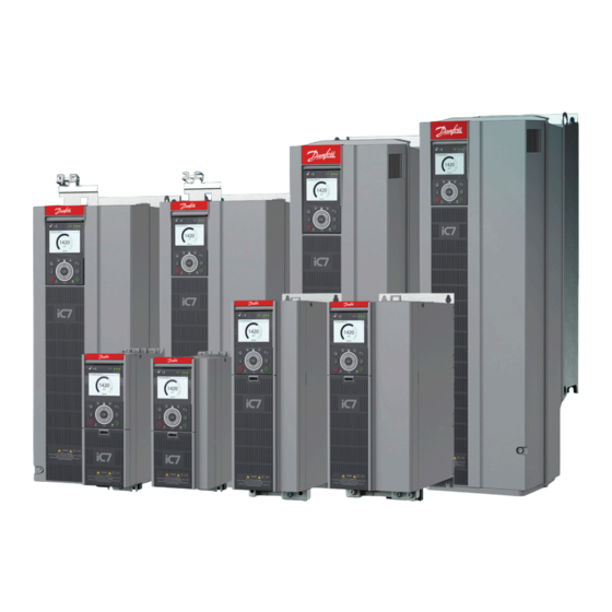
Danfoss iC7 Installation Manual
Automation frequency converters
Hide thumbs
Also See for iC7:
- Application manual (382 pages) ,
- Operating manual (64 pages) ,
- Installation manual (36 pages)
Summary of Contents for Danfoss iC7
- Page 1 Installation Guide iC7-Automation Frequency Converters FA02–FA08/FK06–FK08 (1.3–170 A) drives.danfoss.com...
-
Page 3: Required Tools
Frequency Converters Installation Guide Instructions 1 Instructions 1.1 Safety and Installation Awareness Both an installation and a safety guide are provided with the drive. Before starting installation, read all safety guidelines and precau- tions in the safety guide (136R0243). For details on cyber security, see Security Features in the application guide (136R0283). Addi- tional resources - including the operating guide, design guide, and application guide - can be downloaded at www.danfoss.com/... -
Page 4: Installing The Drive
Install the motor, mains, and ground wiring (step 8). Route the control cables (step 9) Securely fasten the cover to the drive. Perform initial drive and motor setup. Consult the application guide. 4 | Danfoss A/S © 2022.05 AN319740057641en-000301 / 136R0242... -
Page 5: Commissioning Test
I/O terminal blocks must be disabled using jumper wires or a jumper clip. One jumper clip is included in the accessory bag. For more information, refer to the iC7 Series Functional Safety Operating Guide (136R0268). W A R N I N G RESIDUAL ROTATION The STO function can be used for asynchronous, synchronous, and permanent magnet motors. -
Page 6: Power Unit
3 (NC) 19 (GND) 4 (Com) 20 (GND) 5 (NO) Basic I/O board* 6 (NC) * Optional. ** Functionality set by parameters. *** Option B is available only in FA02–FA05/FK02–FK05. Illustration 2: 6 | Danfoss A/S © 2022.05 AN319740057641en-000301 / 136R0242... - Page 7 Frequency Converters Installation Guide Instructions FA02–FA08/FK02–FK08 Type 1 L (cu. ft) 05-01A3 FA02 10 A, gG 4 A, RK5 52 (1.8) 52 (1.8) 10 A, gG 6 A, RK5 05-01A8 FA02 52 (1.8) 10 A, gG 05-02A4 FA02 8 A, RK5 52 (1.8)
- Page 8 35–95 (2–3/0) 29 (1.1) 35–95 (2–3/0) 05-147A FK08 50–120 (1–4/0) 29 (1.1) 05-170A FA08 50–150 (1–300 mcm) 35–95 (2–3/0) 29 (1.1) 05-170A FK08 50–120 (1–4/0) 35–95 (2–3/0) 29 (1.1) Illustration 4: 8 | Danfoss A/S © 2022.05 AN319740057641en-000301 / 136R0242...
- Page 9 Frequency Converters Installation Guide Instructions FA02–FA05 – [2 Nm (18 in-lb)] Illustration 5: Danfoss A/S © 2022.05 AN319740057641en-000301 / 136R0242 | 9...
- Page 10 Frequency Converters Installation Guide Instructions X101 X102 Illustration 6: 10 | Danfoss A/S © 2022.05 AN319740057641en-000301 / 136R0242...
- Page 11 Frequency Converters Installation Guide Instructions FA06–FA08 See Tech. Doc for Info 11 24V 45 24V 12 24V 46 S.INA+ 13 DI1 47 S.INB+ 14 DI2 48 S.FB+ 15 DI/DO1 16 DI/DO2 17 DI3 45 GND 18 DI4 46 S.INA- 19 GND 47 S.INB-...
- Page 12 Frequency Converters Installation Guide Instructions FK06–FK08 X102 X101 – [3.5 Nm (31 in-lb)] ( ! ) – [2 Nm (18 in-lb)] Illustration 8: 12 | Danfoss A/S © 2022.05 AN319740057641en-000301 / 136R0242...
- Page 13 Frequency Converters Installation Guide Instructions FA02–FA08/FK02–FK08 [mm (in)] FA02 FA03 FA04 FA05 FA06/FK06 FA07/FK07 FA08/FK08 257 (10.1) 257 (10.1) 380 (15.0) 380 (15.0) 535 (21.1) 580 (22.1) 721 (28.4) 70 (2.8) 94 (3.7) 105 (4.1) 140 (5.5) 170 (6.7) 200 (7.9)
- Page 14 Frequency Converters Installation Guide Instructions FK06–FK08 Illustration 10: 14 | Danfoss A/S © 2022.05 AN319740057641en-000301 / 136R0242...
- Page 15 Frequency Converters Installation Guide Instructions FA02–FA08/FK02–FK08 45 46 47 48 16 17 18 19 20 31 32 61 62 41 42 43 44 45 46 47 48 11 12 13 14 15 16 17 18 19 20 61 62...
- Page 16 -DC R- DC/R SL1/PZ1 L1, L2, L3 [0.7 Nm (6 in-lb)] U, V, W [0.7 Nm (6 in-lb)] -DC, R-, +DC/R+ [0.7 Nm (6 in-lb)] [2 Nm (18 in-lb)] Illustration 12: 16 | Danfoss A/S © 2022.05 AN319740057641en-000301 / 136R0242...
- Page 17 Frequency Converters Installation Guide Instructions FA04–FA05 WARN READY FAULT L1, L2, L3 1.2–1.5 Nm (11–13 in-lb) DC/R FA04 U, V, W 1.2–1.5 Nm (11–13 in-lb) -DC, R-, +DC, R+ 1.2–1.5 Nm (11–13 in-lb) L1, L2, L3 2.0–2.5 Nm (18–22 in-lb) U, V, W 2.0–2.5 Nm (18–22 in-lb)
- Page 18 16 mm (6 AWG) FA07 95 mm (3/0 AWG) FA07 50 mm (1 AWG) FA08 150 mm (300 mcm) 50 mm (1 AWG) FA08 95 mm (3/0 mcm) 35 mm (2 AWG) Illustration 14: 18 | Danfoss A/S © 2022.05 AN319740057641en-000301 / 136R0242...
- Page 19 Frequency Converters Installation Guide Instructions FK06–FK08 WARN READY FAULT L1, L2, L3 14 Nm (124 in-lb) FK06 U, V, W 14 Nm (124 in-lb) -DC, R-, +DC/R+ 14 Nm (124 in-lb) L1, L2, L3 14 Nm (124 in-lb) FK07...
- Page 20 61 24V ext 31 A01 32 +10V 62 GND 33 AI1 34 AI2 35 GND WARN 1 COM READY 2 NO FAUL 3 NC PUSH 4 COM 5 NO 6 NC Illustration 16: 20 | Danfoss A/S © 2022.05 AN319740057641en-000301 / 136R0242...
- Page 21 Frequency Converters Installation Guide Instructions Illustration 17: Danfoss A/S © 2022.05 AN319740057641en-000301 / 136R0242 | 21...
- Page 22 Frequency Converters Installation Guide Instructions Illustration 18: 22 | Danfoss A/S © 2022.05 AN319740057641en-000301 / 136R0242...
- Page 23 Frequency Converters Installation Guide Instructions Danfoss A/S © 2022.05 AN319740057641en-000301 / 136R0242 | 23...
- Page 24 Danfoss reserves the right to alter its products without notice. This also applies to products ordered but not delivered provided that such alterations can be made without changes to form, fit or function of the product. All trademarks in this material are property of Danfoss A/S or Danfoss group companies.

