
Related Manuals for Omron SYSMAC C200H CPU01-E


Summary of Contents for Omron SYSMAC C200H CPU01-E
- Page 1 All manuals and user guides at all-guides.com Cat. No. W111-E1-10 SYSMAC Programmable Controllers C200H (CPU01-E/03-E/11-E) INSTALLATION GUIDE Downloaded from Elcodis.com electronic components distributor...
- Page 2 All manuals and user guides at all-guides.com Downloaded from Elcodis.com electronic components distributor...
- Page 3 All manuals and user guides at all-guides.com C200H Programmable Controllers (CPU01-E/03-E/11-E) Installation Guide Revised January 2001 Downloaded from Elcodis.com electronic components distributor...
- Page 4 Buyer indemnifies Omron against all related costs or expenses. rights of another party. 10. Force Majeure. Omron shall not be liable for any delay or failure in delivery 16. Property; Confidentiality. Any intellectual property in the Products is the exclu-...
- Page 5 OMRON. No patent liability is assumed with respect to the use of the information contained herein. Moreover, because OMRON is constantly striving to improve its high-quality products, the information contained in this manual is subject to change without notice.
- Page 6 All manuals and user guides at all-guides.com Downloaded from Elcodis.com electronic components distributor...
-
Page 7: Table Of Contents
All manuals and user guides at all-guides.com TABLE OF CONTENTS PRECAUTIONS ....... . . 1 Intended Audience . - Page 8 All manuals and user guides at all-guides.com TABLE OF CONTENTS Appendices A Inspection and Maintenance ..........B Specifications .
- Page 9 All manuals and user guides at all-guides.com About this Manual: This manual explains how to install a C-series C200H Programmable Controller (CPU01-E/03-E/11-E). Section 1 is an introduction to Programmable Controllers. General information about what a Programma- ble Controller can do and how a Programmable Controller works is provided. Section 2 provides a description of all the components of the C200H.
- Page 10 All manuals and user guides at all-guides.com Downloaded from Elcodis.com electronic components distributor...
- Page 11 All manuals and user guides at all-guides.com PRECAUTIONS This section provides general precautions for using the Programmable Controller (PC) and related devices. The information contained in this section is important for the safe and reliable application of the Programmable Con- troller.
-
Page 12: Intended Audience
It is extremely important that a PC and all PC Units be used for the specified purpose and under the specified conditions, especially in applications that can directly or indirectly affect human life. You must consult with your OMRON representative before applying a PC System to the above-mentioned applications. -
Page 13: Operating Environment Precautions
All manuals and user guides at all-guides.com Application Precautions Operating Environment Precautions Caution Do not operate the control system in the following places: • Locations subject to direct sunlight. • Locations subject to temperatures or humidity outside the range specified in the specifications. - Page 14 All manuals and user guides at all-guides.com Application Precautions • Interlock circuits, limit circuits, and similar safety measures in external circuits (i.e., not in the Programmable Controller) must be provided by the customer. • Always use the power supply voltage specified in the operation manuals. An incorrect voltage may result in malfunction or burning.
-
Page 15: Introduction
All manuals and user guides at all-guides.com SECTION 1 Introduction This section provides general information about Programmable Controllers (PCs) and how they fit into a Control System. What is a Control System? ..........The Role of the PC . -
Page 16: What Is A Control System
All manuals and user guides at all-guides.com What is a Control System? Section What is a Control System? A Control System is the electronic equipment needed to control a particular process. It may include everything from a process control computer, if one is used, to the factory computer, down through the PCs (and there may be many of them networked together) and then on down through the network to the control components: the switches, stepping motors, solenoids, and sensors which... - Page 17 All manuals and user guides at all-guides.com What is a Control System? Section A Position Control System Input Unit Position Control Unit Signal line for Servomotor driver control Hand-held Programming Console Power source Control panel Control switch DC Servomotor Power Driver source DC Servomotor...
-
Page 18: The Role Of The Pc
All manuals and user guides at all-guides.com The Role of the PC Section The Role of the PC The PC is the part of the Control System that directly controls the manufacturing process. According to the program stored in its memory, the PC accepts data from the input devices connected to it, and uses this data to monitor the con- trolled system. - Page 19 All manuals and user guides at all-guides.com The Role of the PC Section 1-2-2 Output Devices A PC can output to a myriad of devices for use in automated control. Almost any- thing that you can think of could be controlled (perhaps indirectly) by a PC. Some of the most common devices are motors, Solenoids, Servomotors, Stepping Motors, valves, switches, indicator lights, buzzers, and alarms.
-
Page 20: How Does A Pc Work
All manuals and user guides at all-guides.com How Does a PC Work? Section How Does a PC Work? PCs operate by monitoring input signals and providing output signals. When changes are detected in the signals, the PC reacts, through the user-pro- grammed internal logic, to produce output signals. - Page 21 All manuals and user guides at all-guides.com How Does a PC Work? Section PC Operation Flowchart Power application Clears data areas and resets System counters Initial processing on power Checks I/O Units application Resets watchdog timer Checks hardware and program memory Sets error flag and Check OK? lights indicator...
- Page 22 All manuals and user guides at all-guides.com Downloaded from Elcodis.com electronic components distributor...
-
Page 23: Description
All manuals and user guides at all-guides.com SECTION 2 Description This section provides information about the individual Units that make up a PC. The names of all the parts of a Unit are given, followed by any details that apply to that Unit alone. For a description of how the Units fit together to become a PC, refer to Section 3 Assembly Instructions. -
Page 24: Cpu Rack
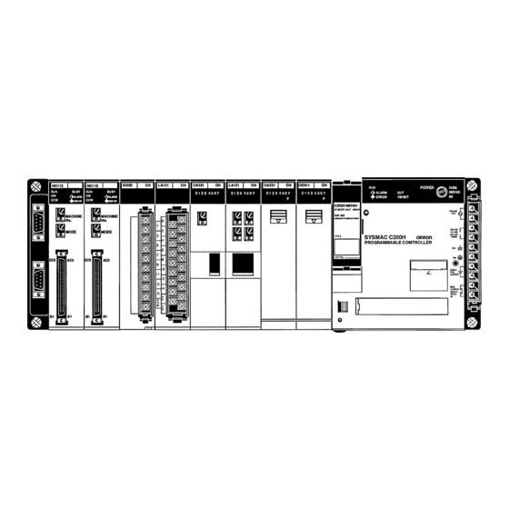
All manuals and user guides at all-guides.com CPU Rack Section CPU Rack The following figure shows the names of all the parts of a CPU Rack. There are four models of Backplanes available with 3, 5, 8 and 10 slots for I/O Units. You can use any of these Backplanes to build a CPU or Expansion I/O Rack. -
Page 25: Cpu
All manuals and user guides at all-guides.com Section The CPU is available in three models. The C200H-CPU01-E and C200H- CPU11-E both run on 100 to 120 or 200 to 240 VAC, and the C200H-CPU03-E runs on 24 VDC. The C200H-CPU11-E is unique in that it connects the SYSMAC LINK Unit or SYSMAC NET Link Unit to the CPU. - Page 26 All manuals and user guides at all-guides.com Section C200H-CPU11-E Indicators Power fuse MF51NR (5.2 dia. x 20 mm) 2A 250 V Memory Pack connector Battery compart- ment Bus connector Available only with the C200H-CPU11-E. Handheld Program- Used to connect this ming Console con- Unit to a SYSMAC nector...
- Page 27 All manuals and user guides at all-guides.com Section Peripheral Device All three CPU models are equipped with two connectors for peripheral devices. Connectors One is used for the Handheld Programming Console or the Data Access Con- sole; the other is used for the CPU-Mounting Programming Console. The C200H-CPU11-E, however, has a third connector that is used for connecting the SYSMAC LINK Unit or the SYSMAC NET Link Unit to the CPU.
- Page 28 All manuals and user guides at all-guides.com Section If you are using the C200H-CPU11-E, a SYSMAC LINK Unit or a SYSMAC LINK Unit can be mounted to either of the two slots to the left of the CPU. They are then connected to the CPU with the Bus Connector Unit.
-
Page 29: Expansion I/O Rack
All manuals and user guides at all-guides.com Expansion I/O Rack Section Expansion I/O Rack The Backplane used to construct a CPU Rack is also used to construct an Ex- pansion I/O Rack. An Expansion I/O Rack is identical to a CPU Rack, except the CPU has been replaced with a Power Supply. -
Page 30: Power Supply
All manuals and user guides at all-guides.com Power Supply Section Power Supply The Power Supply used for Expansion I/O Racks is available in two models. One runs on 100 to 120 or 200 to 240 VAC, and the other runs on 24 VDC. AC Power Supply POWER Power fuse 2 A 250 V... - Page 31 All manuals and user guides at all-guides.com Power Supply Section DC Power Supply POWER Power fuse 5 A 125 V indicator (green) (5.2-dia. x 20) Lights when power is MF51NR supplied to Power Supply 24 VDC Terminals for external connections (See note.) Note The LG and GR terminals are connected internally.
-
Page 32: I/O Units
All manuals and user guides at all-guides.com I/O Units Section I/O Units I/O Units come in three shapes: A-shape, B-shape, and E-shape. Refer to Ap- pendix B Specifications for the dimensions of each Unit. A-shape I/O Units I/O Unit lock notch Nameplate I/O indicators Indicate ON/OFF sta-... -
Page 33: Memory Units
All manuals and user guides at all-guides.com Memory Units Section E-shape I/O Units I/O Unit lock notch Nameplate I/O indicators Indicate ON/OFF status of points 10-terminal terminal block Memory Units There are three types of Memory Units, having three different types of memory. The three types of memory are EPROM, EEPROM, and RAM. - Page 34 All manuals and user guides at all-guides.com Memory Units Section EPROM Unit The data that you wish to store in an EPROM Unit must first be written to an EPROM Chip, using the PROM Writer. Then the EPROM Chip must be mounted to the inside of the EPROM Unit.
- Page 35 All manuals and user guides at all-guides.com Memory Units Section Model Function C200H-CPU01-E/03 25308 Battery failure in RAM Unit C200H-CPU11-E 25308 Battery failure in RAM Unit or AR2404 Battery failure in CPU In the following table, the ON/OFF status of the bits indicate where battery failure took place in the C200H-CPU11-E.
- Page 36 All manuals and user guides at all-guides.com Downloaded from Elcodis.com electronic components distributor...
-
Page 37: Assembly Instructions
All manuals and user guides at all-guides.com SECTION 3 Assembly Instructions When we speak of a PC, we usually think of it as a single object. But actually even the simplest PCs are usually composed of several different devices. In fact a single PC can be physically spread throughout a building, but we still call it one PC. Mounting the Units . -
Page 38: Mounting The Units
All manuals and user guides at all-guides.com Mounting the Units Section Mounting the Units There is no single Unit that can be said to constitute a Rack PC. To build a Rack PC, we start with a Backplane. The Backplane for the C200H is shown below. C200H Backplane The Backplane is a simple device having two functions. - Page 39 All manuals and user guides at all-guides.com Mounting the Units Section The figure below shows one I/O Unit mounted directly to the left of the CPU. I/O Units are where the control connections are made from the PC to all the vari- ous input devices and output devices.
- Page 40 All manuals and user guides at all-guides.com Mounting the Units Section This Backplane has I/O Units mounted to it, but it has no CPU of its own. The additional Backplane must also have an Expansion I/O Power Supply mounted to its rightmost position. This configuration of additional Backplane, Expansion I/O Power Supply, and I/O Units is called an Expansion I/O Rack.
-
Page 41: Memory Packs
All manuals and user guides at all-guides.com Memory Packs Section Memory Packs The CPU has a removable Memory Pack that stores the user program. Memory Packs are available with three types of memory; EPROM, EEPROM, and RAM (refer to Section 2-6 Memory Packs ). If this is your first C200H, then you must have a RAM Pack in order to write and test the program you are going to use. - Page 42 All manuals and user guides at all-guides.com Memory Packs Section 4. On the printed circuit board there is a socket for the EPROM Chip. On the socket you will find a notch. Align the notch on the socket with the notch on the EPROM Chip and mount the EPROM Chip to the socket as shown be- low.
-
Page 43: System Configurations
All manuals and user guides at all-guides.com System Configurations Section How to Mount the Mount the Memory Pack to the CPU by following the steps below. Memory Pack to the CPU 1, 2, 3... 1. Turn OFF the power to the PC. Caution Do not attempt to mount the Memory Pack to the CPU while the power to the PC is ON. - Page 44 All manuals and user guides at all-guides.com System Configurations Section Host Link Unit and Special I/O Units I/O Units Memory Packs Remote I/O Master Unit • • • • Up to ten Special I/O Up to two Units can be I/O Units available with 5, 8, RAM, EPROM, or EE- Units can be mounted.
-
Page 45: System Connections
All manuals and user guides at all-guides.com SECTION 4 System Connections In the preceding sections we have covered what all the parts of a PC are and how they should be assembled. This section provides detailed information about the types of considerations involved in making all of the PC connections. Also included in this section are considerations that should be kept in mind when using the C200H-CPU11-E as the CPU. -
Page 46: Ir Word Allocation
All manuals and user guides at all-guides.com IR Word Allocation Section IR Word Allocation Each slot of the Backplane is assigned a hardware word number. This word is accessible for I/O use only in the given slot. However, standard I/O Units are available in 5-, 8-, 12-, and 16-point models. - Page 47 All manuals and user guides at all-guides.com IR Word Allocation Section The CPU Rack begins with word 000 at the leftmost slot. The first Expansion I/O Rack begins with word 010, and the second Expansion I/O Rack with word 020. The first word of each Rack is fixed, regardless of the model of Backplane used.
-
Page 48: Remote I/O
All manuals and user guides at all-guides.com Remote I/O Section The following figure shows the word allocation for a fully expanded C200H with three 8-slot Backplanes. word word word word word word word word word word word word word word word word Power... -
Page 49: Maximum Current And Power Supplied
All manuals and user guides at all-guides.com Maximum Current and Power Supplied Section In addition, when PC Link Units are used, a maximum of ten Special I/O Units and PC Link Units total can be mounted to one Expanded PC. When a High-den- sity I/O Unit is mounted to a Remote I/O Slave Rack, the RM001-PV1 or RM201 Remote I/O Master Unit must be used. - Page 50 All manuals and user guides at all-guides.com Maximum Current and Power Supplied Section Deductions Table CPU11-E 5-V CPU01/03-E 5-V Peripheral device deductions consumption (I/O card) consumption (I/O card) ≤ ≤ None 1.4 A 1.6 A ≤ ≤ PROM Writer and CPU-mounting Host Link Unit >...
- Page 51 All manuals and user guides at all-guides.com Maximum Current and Power Supplied Section Unit Model number Current consumption SYSMAC NET Link Unit C200HS-SNT32 1.0 A Feed Adapter C200H-APS01/ASP02 TTL Input C200H-ID501 0.13 A DC Input C200H-ID215 TTL Output C200H-OD501 0.22 A Transistor Output C200H-OD215 TTL I/O...
- Page 52 All manuals and user guides at all-guides.com Maximum Current and Power Supplied Section Note *With all eight bits on simultaneously. Current Drawn from 24-V Unit Model number Current Supply consumption No-Voltage Contact C200H-ID001/ID002 0.06 A Input Units Calculation Examples The total power consumption for each Rack can be obtained from the following formulas: Total power consumption for each Unit + 7 (8) CPU Rack =...
- Page 53 All manuals and user guides at all-guides.com Maximum Current and Power Supplied Section • High-density and Mixed I/O Units (MD215): • Current for MD215: 0.3 A Example 4 Assume that the following Units are mounted to a rack to which is mounted the C200H-CPU11-E.
-
Page 54: I/O Connections
All manuals and user guides at all-guides.com I/O Connections Section I/O Connections Connect the I/O Devices to the I/O Units using AWG 22 (cross-sectional area of 0.3 mm ) for 19-terminal terminal blocks and AWG 22 to 18 lead wire (cross-sec- tional area of 0.3 to 0.75 mm ) for 10 terminal terminal blocks. - Page 55 All manuals and user guides at all-guides.com I/O Connections Section I/O Unit Cover A C200H-COV11 Cover is provided as an I/O Unit cover for Units that use 10P terminal block connectors. After the I/O wiring has been completed, slide the cover up from the bottom, as shown in the illustration below.
- Page 56 All manuals and user guides at all-guides.com I/O Connections Section DC Input Units Contact output DC input When using the configuration shown below, the sensor and Input Unit should receive their power from the same supply. NPN current output Current regulator DC input Output...
- Page 57 All manuals and user guides at all-guides.com I/O Connections Section AC Input Units Contact output AC input AC Switching AC input Prox. switch main circuit Caution When using Reed switch as the input contacts for AC Input Units, be sure the allowable current of the switch is at least 1 A.
- Page 58 All manuals and user guides at all-guides.com Downloaded from Elcodis.com electronic components distributor...
-
Page 59: Installation Environment
All manuals and user guides at all-guides.com SECTION 5 Installation Environment This section details the necessary environment and conditions for installation of the PC. For specific instructions on mounting Units and wiring for I/O and power, refer to Section 2-4 Power Supply and Section 3-3 System Configurations. Installation Environment . - Page 60 All manuals and user guides at all-guides.com Installation Environment Section Installation Environment This section details the necessary environmental conditions for installing the Caution Static electricity can damage PC components. Your body can carry an electro- static charge, especially when the humidity is low. Before touching the PC, be sure to first touch a grounded metallic object, such as a metal water pipe, in order to discharge any static build-up.
-
Page 61: Mounting Requirements
(refer to Appendix B Specifications ). If you want to mount the PC on DIN Rail, you can order a DIN Rail from OMRON (refer to Ap- pendix B Standard Models ). DIN Rails come in the two heights shown below. - Page 62 All manuals and user guides at all-guides.com Mounting Requirements Section DIN Rail Mounting The DIN Rail Mounting Bracket shown below is necessary for mounting the PC Bracket to the DIN Rail. Procedure 1, 2, 3... 1. The following diagram is a view of the back of the Backplane. Attach one Mounting Bracket to the left and right sides of the Backplane as shown be- low.
-
Page 63: Duct Work
All manuals and user guides at all-guides.com Duct Work Section 3. Loosen the screws attaching the Mounting Brackets to the Backplane. Slide the Backplane upward as shown below so that the Mounting Bracket and Backplane clamp securely onto the DIN Rail. Tighten the screws. DIN Rail Mounting Bracket DIN Rail Hold-down bracket... -
Page 64: Preventing Noise
All manuals and user guides at all-guides.com Preventing Noise Section If the I/O wiring and power cables must be placed in the same duct (for example, where they are connected to the equipment), they must be shielded from each other using grounded metal plates. Metal plate (iron) 200 mm min. -
Page 65: Power Considerations
All manuals and user guides at all-guides.com SECTION 6 Power Considerations Use a commercially available 100 to 120 VAC, 200 to 240 VAC, or 24 VDC power source, according to the model of PC you are using (refer to Appendix B Specifications). Expansion I/O Racks, if used, must also be connected to the power source. If possible, use independent power sources for the PC, input devices, and output devices. -
Page 66: Grounding
All manuals and user guides at all-guides.com Emergency Stop Section Grounding The Line Ground (LG) terminal is a noise-filtered neutral terminal that does not normally require grounding. If electrical noise is a problem, however, this termi- nal should be connected to the Ground (GR) terminal. To avoid electrical shock, attach a grounded (earth ground) AWG 14 wire (cross- sectional area of at least 2 mm ) to the GR terminal. -
Page 67: Wiring
All manuals and user guides at all-guides.com Wiring Section Power Failure A sequential circuit is built into the PC to handle power interruptions. This circuit prevents malfunctions due to momentary power loss or voltage drops. A timing diagram for the operation of this circuit is shown below. The PC ignores all momentary power failures if the interruption lasts no longer than 10 ms. - Page 68 All manuals and user guides at all-guides.com Wiring Section Caution Tighten the AC Power Supply terminals on the terminal blocks to the torque of 0.8 N S m. Insufficient tightening may cause short-circuiting, malfunction, or burning. C200H-CPU03-E Screw (3.5 mm head with Breaker self-raising pressure plate) •...
-
Page 69: Safety Considerations
All manuals and user guides at all-guides.com SECTION 7 Safety Considerations There are certain safety requirements to be considered when installing the PC. Some of these, such as the emergency stop circuit (refer to Section 2-4 Power Supply), are part of the initial wiring. The considerations described below should be kept in mind when operating the PC and when connecting I/O devices to the PC. -
Page 70: Interlock Circuits
All manuals and user guides at all-guides.com Wiring Section Interlock Circuits When the PC controls an operation such as the clockwise and counterclockwise operation of a motor, provide an external interlock such as the one shown below to prevent both the forward and reverse outputs from turning ON at the same time. - Page 71 All manuals and user guides at all-guides.com Wiring Section Output Leakage Current If there is a possibility of leakage current causing a transistor or triac to malfunc- tion, connect a bleeder resistor across the output as shown below. Load power supply Bleeder resistor Determine the value and rating for the bleeder resistor using the following for- mula.
- Page 72 All manuals and user guides at all-guides.com Wiring Section Inductive Load Surge When an inductive load is connected to an I/O Unit, it is necessary to connect a Suppressor surge suppressor or diode in parallel with the load as shown below. This is so that the back EMF generated by the load will be absorbed.
- Page 73 All manuals and user guides at all-guides.com Appendix A Inspection and Maintenance Certain consumable items in a PC (such as fuses, Relays, or batteries) need occasional replacement. This Appen- dix explains how to replace each of these items. Refer to Appendix B for the specifications of individual consum- able items.
- Page 74 All manuals and user guides at all-guides.com Inspection and Maintenance Appendix A 1, 2, 3... 1. Turn OFF the power to the PC. 2. Detach the terminal block by unlocking the lock levers at the top and bottom of the terminal block. 3.
- Page 75 All manuals and user guides at all-guides.com Inspection and Maintenance Appendix A 3. While pushing down the lock lever on the Backplane with a screwdriver as shown below, remove the Output Unit. 4. Remove the screw from the top of the Unit (Phillips screwdriver). 5.
- Page 76 All manuals and user guides at all-guides.com Inspection and Maintenance Appendix A OC222 OC223 OC225 7. A Relay puller is provided inside the rear of the case when the Unit is deliv- ered. Use the Relay puller to pull out the Relay as shown below. Insert a new Relay.
- Page 77 All manuals and user guides at all-guides.com Inspection and Maintenance Appendix A Batteries Some RAM Packs use a battery (refer to Appendix B for specifications). When the battery is nearly discharged, the ALARM indicator blinks and the message “BATT FAIL” appears on the Programming Console. When this occurs, replace the battery within one week to avoid loss of data.
- Page 78 All manuals and user guides at all-guides.com Downloaded from Elcodis.com electronic components distributor...
- Page 79 All manuals and user guides at all-guides.com Appendix B Specifications The following series of figures and tables provides a complete set of specifications for each Unit of the C200H. Note that I/O Units may take on one of three different shapes. Thus I/O Units are sometimes referred to as A-shape I/O Units, B-shape, or E-shape I/O Units.
- Page 80 All manuals and user guides at all-guides.com Specifications Appendix B CPU Specifications Main Control Element MPU, CMOS, LS-TTL Programming Method Ladder diagram Instruction Length 1 address/instruction, 1 to 4 words/instruction Number of Instructions 145 (12 basic instructions + 133 special instructions) C200H-CPU11 159 (12 basic instructions + 147 special instructions) Basic instructions: 0.75 to 2.25 ms Special instructions: 34 to 724 ms...
- Page 81 All manuals and user guides at all-guides.com Specifications Appendix B AC Input Unit C200H-IA121 Rated Input Voltage 100 to 120 VAC 50/60 Hz Operating Input Voltage 85 to 132 VAC 50/60 Hz Input Impedance 9.7 kW (50 Hz), 8 kW (60 Hz) Input Current 10 mA typical (at 100 VAC) ON Voltage...
- Page 82 All manuals and user guides at all-guides.com Specifications Appendix B AC Input Unit C200H-IA122/IA122V Rated Input Voltage 100 to 120 VAC 50/60 Hz Operating Input Voltage 85 to 132 VAC 50/60 Hz Input Impedance 9.7 kW (50 Hz), 8 kW (60 Hz) Input Current 10 mA typical (at 100 VAC) ON Voltage...
- Page 83 All manuals and user guides at all-guides.com Specifications Appendix B AC Input Unit C200H-IA221 Rated Input Voltage 200 to 240 VAC 50/60 Hz Operating Input Voltage 170 to 264 VAC 50/60 Hz Input Impedance 21 kW (50 Hz), 18 kW (60 Hz) Input Current 10 mA typical (at 200 VAC) ON Voltage...
- Page 84 All manuals and user guides at all-guides.com Specifications Appendix B AC Input Unit C200H-IA222/IA222V Rated Input Voltage 200 to 240 VAC 50/60 Hz Operating Input Voltage 170 to 264 VAC 50/60 Hz Input Impedance 21 kW (50 Hz), 18 kW (60 Hz) Input Current 10 mA typical (at 200 VAC) ON Voltage...
- Page 85 All manuals and user guides at all-guides.com Specifications Appendix B No-Voltage Contact Input Unit C200H-ID001 Input Voltage No-voltage contact/NPN output type (negative common) Input Impedance 3 kW Input Current 7 mA typical ON Voltage (14.4 VDC min.) OFF Voltage (5.0 VDC max.) ON Response Time 1.5 ms max.
- Page 86 All manuals and user guides at all-guides.com Specifications Appendix B No-Voltage Contact Input Unit C200H-ID002 Input Voltage No-voltage contact/NPN output type (positive common) Input Impedance 3 kW Input Current 7 mA typical ON Voltage (14.4 VDC min.) OFF Voltage (5.0 VDC max.) ON Response Time 1.5 ms max.
- Page 87 All manuals and user guides at all-guides.com Specifications Appendix B DC Input Unit C200H-ID211 Rated Input Voltage 12 to 24 VDC Operating Input Voltage 10.2 to 26.4 VDC Input Impedance 2 kW Input Current 10 mA (at 24 VDC) ON Voltage 10.2 VDC min.
- Page 88 All manuals and user guides at all-guides.com Specifications Appendix B DC Input Unit C200H-ID212 Rated Input Voltage 24 VDC Operating Input Voltage 20.4 to 26.4 VDC Input Impedance 3 kW Input Current 7 mA (at 24 VDC) ON Voltage 14.4 VDC min. OFF Voltage 5.0 VDC max.
- Page 89 All manuals and user guides at all-guides.com Specifications Appendix B AC/DC Input Unit C200H-IM211 Rated Input Voltage 12 to 24 VDC Operating Input Voltage 10.2 to 26.4 VDC Input Impedance 2 kW Input Current 10 mA typical (at 24 VDC) ON Voltage 10.2 VDC min.
- Page 90 All manuals and user guides at all-guides.com Specifications Appendix B AC/DC Input Unit C200H-IM212 Rated Input Voltage 24 VDC Operating Input Voltage 20.4 to 26.4 VDC Input Impedance 3 kW Input Current 7 mA typical (at 24 VDC) ON Voltage 14.4 VDC min.
- Page 91 All manuals and user guides at all-guides.com Specifications Appendix B Triac Output Unit C200H-OA222V Max. Switching Capacity 0.3 A 250 VAC, 50/60 Hz (2 A/Unit) Min. Switching Capacity 10 mA (resistive load)/40 mA (inductive load) 10 VAC Leakage Current 3 mA (100 VAC) max./6 mA (200 VAC) max. Residual Voltage 1.2 V max.
- Page 92 All manuals and user guides at all-guides.com Specifications Appendix B Triac Output Unit C200H-OA121-E Max. switching capacity 1 A 120 VAC, 50/60 Hz (4 A/Unit) Min. switching capacity 10 mA (resistive load)/40 mA (inductive load) 10 VAC Leakage Current 3 mA (100 VAC) max. Residual Voltage 1.2 V max.
- Page 93 All manuals and user guides at all-guides.com Specifications Appendix B Triac Output Unit C200H-OA122-E Max. Switching Capacity 1.2 A 120 VAC, 50/60 Hz (4 A/Unit) Max. Inrush Current 15 A (pulse width: 100 ms) 30 A (pulse width: 10 ms) Min.
- Page 94 All manuals and user guides at all-guides.com Specifications Appendix B Triac Output Unit C200H-OA223 Max. Switching Capacity 1.2 A 250 VAC, 50/60 Hz (4 A/Unit) Max. Inrush Current 15 A (pulse width: 100 ms) 30 A (pulse width: 10 ms) Min.
- Page 95 All manuals and user guides at all-guides.com Specifications Appendix B Triac Output Unit C200H-OA224 Max. Switching Capacity 0.5 A 250 VAC, 50/60 Hz (2 A/Unit) Max. Inrush Current 10 A (pulse width: 100ms) 20 A (pulse width: 10 ms) Min. Switching Capacity 100 mA 10 VAC/50 mA 24 VAC/10 mA 100 VAC min.
- Page 96 All manuals and user guides at all-guides.com Specifications Appendix B Contact Output Unit C200H-OC221 Max. switching capacity 2 A 250 VAC (cos of phase angle = 1), 2 A 250 VAC (cos of phase angle = 0.4), 2 A 24 VDC 8 A/Unit Min.
- Page 97 All manuals and user guides at all-guides.com Specifications Appendix B Contact Output Unit C200H-OC222 Max. switching capacity 2 A 250 VAC (cos of phase angle = 1), 2 A 250 VAC (cos of phase angle = 0.4), 2 A 24 VDC 8 A/Unit Min.
- Page 98 All manuals and user guides at all-guides.com Specifications Appendix B Contact Output Unit C200H-OC223 Max. switching capacity 2 A 250 VAC (cos of phase angle = 1), 2 A 250 VAC (cos of phase angle = 0.4), 2 A 24 VDC 10 A/Unit Min.
- Page 99 All manuals and user guides at all-guides.com Specifications Appendix B Contact Output Unit C200H-OC224 Max. switching capacity 2 A 250 VAC (cos of phase angle = 1), 2 A 250 VAC (cos of phase angle = 0.4), 2 A 24 VDC 16 A/Unit Min.
- Page 100 All manuals and user guides at all-guides.com Specifications Appendix B Contact Output Unit C200H-OC225 Max. switching capacity 2 A 250 VAC (cos of phase angle = 1), 2 A 250 VAC (cos of phase angle = 0.4), 2 A 24 VDC 8 A/Unit Min.
- Page 101 All manuals and user guides at all-guides.com Specifications Appendix B Transistor Output Unit C200H-OD211 +10% Max. switching capacity 0.3 A 24 VDC (2 A/Unit) –15% Min. switching capacity None Leakage Current 0.1 mA max. Residual Voltage 1.4 V max. ON Response Time 0.2 ms max.
- Page 102 All manuals and user guides at all-guides.com Specifications Appendix B Transistor Output Unit C200H-OD212 +10% Max. switching capacity 0.3 A 24 VDC (4.8 A/Unit) –15% Min. switching capacity None Leakage Current 0.1 mA max. Residual Voltage 1.4 V max. ON Response Time 0.2 ms max.
- Page 103 All manuals and user guides at all-guides.com Specifications Appendix B Transistor Output Unit C200H-OD213 +10% Max. switching capacity 2.1 A 24 VDC (5.2 A/Unit) NPN output –15% Min. switching capacity None Leakage Current 0.1 mA max. Residual Voltage 1.4 V max. ON Response Time 0.2 ms max.
- Page 104 All manuals and user guides at all-guides.com Specifications Appendix B Transistor Output Unit C200H-OD214 (Sourcing Type) +10% Max. switching capacity 24 VDC 0.8 A (2.4 A/Unit) surge current –15% 2 A (sourcing type) PNP output Min. switching capacity None Leakage Current 1 mA max.
- Page 105 All manuals and user guides at all-guides.com Specifications Appendix B C200H-OD214 Short-Circuit Protection The C200H-OD214 Output Unit is equipped with two types of short-circuit pro- tection. One is overcurrent protection, and the other is thermal protection. The short-circuit should be eliminated immediately in order to avoid damage to the Unit.
- Page 106 All manuals and user guides at all-guides.com Specifications Appendix B Programming Example If there is a short-circuit in an output, we want the pro- gram to turn that output OFF. Assume that the Unit is mounted at word 000. A program to turn OFF output bits 00 and 01 is shown below.
- Page 107 All manuals and user guides at all-guides.com Specifications Appendix B Transistor Output Unit C200H-OD216 Max. switching capacity 0.3 A 5 to 24 VDC Min. switching capacity 10 mA 5 VDC Leakage Current 0.1 mA max. Residual Voltage 1.5 V max. ON Response Time 1.5 ms max.
- Page 108 All manuals and user guides at all-guides.com Specifications Appendix B Transistor Output Unit C200H-OD217 Max. switching capacity 0.3 A 5 to 24 VDC Min. switching capacity 10 mA 5 VDC Leakage Current 0.1 mA max. Residual Voltage 1.5 V max. ON Response Time 1.5 ms max.
- Page 109 All manuals and user guides at all-guides.com Specifications Appendix B Transistor Output Unit C200H-OD411 Max. switching capacity 12 to 48 VDC 1 A (3 A/Unit) Min. switching capacity None Leakage Current 0.1 mA max. Residual Voltage 1.4 V max. ON Response Time 0.2 ms max.
- Page 110 All manuals and user guides at all-guides.com Specifications Appendix B Transistor Output Unit C200H-OD21A (Sourcing Type with Load Circuit Protection) +10% Max. switching 24 VDC , 1.0 A (4 A/Unit) No. of Circuits 1 (16 points/common) –15% capacity surge current 1.6 A (sourcing type) PNP output Min.
- Page 111 All manuals and user guides at all-guides.com Specifications Appendix B Terminal Connections +24 VDC 24 VDC Note 1. When the ALARM output turns ON, remove the cause of the high current and then shut off the external power supply for approx. 1 second. After confirming that the cause has been removed, turn ON the pow- er supply again to reset the output.
- Page 112 All manuals and user guides at all-guides.com Specifications Appendix B Analog Timer Unit Item Specifications Oscillation Method RC oscillation Time Setting Range Use the DIP switch to set any of the following four ranges, according to the chart shown on the next page.
- Page 113 All manuals and user guides at all-guides.com Specifications Appendix B Internal variable resistors TM001 Indicators These variable re- The SET indicators in the top row light when the cor- sistors are used to responding timer is operating. The TIME UP indica- set the timers.
- Page 114 All manuals and user guides at all-guides.com Specifications Appendix B Caution Ensure that the external variable resistor connectors are open when using the internal variable resistor. External variable resistor connector External variable resistor B7A Interface Unit C200H-B7Aj1 (Basic I/O Unit Type) The B7A Interface Unit used with the B7A Link Terminal allows the transmission and reception of 16-point I/O data over two wires.
- Page 115 All manuals and user guides at all-guides.com Specifications Appendix B Connection Terminals SIG: Connects to the SIG terminal of the B7A Link Terminal. V–: Connects to the negative power terminal of the B7A Link Terminal. Caution If the terminals are not connected correctly, the internal circuitry of the B7A Link Terminal will be damaged.
- Page 116 All manuals and user guides at all-guides.com Specifications Appendix B Dimensions Racks The dimensions shown below are for both the CPU Rack and Expansion I/O Rack. The C dimension for the Pro- gramming Console will increase by 30mm when the Programming Console Adapter C200H-BP001 is used, and will increase by 50 mm when the Programming Console Adapter C200H-BP002 is used.
- Page 117 All manuals and user guides at all-guides.com Specifications Appendix B Mounted Unit CPU01/03 CPU11 Programming Console Other peripheral devices B-shape I/O Units E-shape I/O Units I/O Units The dimensions shown below are for the three shapes of I/O Units mentioned throughout these specifications. A-shape I/O Units Back- plane...
- Page 118 All manuals and user guides at all-guides.com Specifications Appendix B E-shape I/O Units Backplane Insulation Plates The dimensions shown below are for Backplane Insulation Plates. PC mounting screws Insulation plate mounting screws Four screws with 4-mm diameter Four screws with 5-mm diameter heads are provided.
- Page 119 All manuals and user guides at all-guides.com Specifications Appendix B I/O Connecting Cables The dimensions shown below are for I/O Connecting Cables. Cable Length (L) C200H-CN311 30 cm C200H-CN711 70 cm C200H-CN221 C200H-CN521 C200H-CN131 10 m Downloaded from Elcodis.com electronic components distributor...
- Page 120 All manuals and user guides at all-guides.com Downloaded from Elcodis.com electronic components distributor...
- Page 121 All manuals and user guides at all-guides.com Appendix C Standard Models The C200H is a Rack-type PC that can be configured many different ways. Here is a series of tables listing the Units available for the C200H, along with a brief description of the Unit and its model number. C200H Racks Name Specifications...
- Page 122 All manuals and user guides at all-guides.com Standard Models Appendix C C200H I/O Units Name Specifications Model number Input Units AC Input Unit 8 pts 100 to 120 VAC C200H-IA121 16 pts 100 to 120 VAC C200H-IA122/IA122V 8 pts 200 to 240 VAC C200H-IA221 16 pts 200 to 240 VAC...
- Page 123 All manuals and user guides at all-guides.com Standard Models Appendix C C200H Special I/O Units All of the following are classified as Special I/O Units except for the ASCII Unit, which is an Intelligent I/O Unit. Name Specifications Model number High-den- DC Input 32 pts...
- Page 124 All manuals and user guides at all-guides.com Standard Models Appendix C Name Specifications Model number Position Control Units 1 axis Pulse output; speeds: 1 to 99,990 pps C200H-NC111 1 axis Directly connectable to servomotor driver; compat- C200H-NC112 ible with line driver; speeds: 1 to 250,000 pps 2 axis 1 to 250000.
- Page 125 All manuals and user guides at all-guides.com Standard Models Appendix C Optional Products Name Specifications Model number I/O Unit Cover Cover for 10-pin terminal block C200H-COV11 Terminal Block Cover Short protection for 10-pin terminal block C200H-COV02 Short protection for 19-pin terminal block C200H-COV03 Connector Cover Protective cover for unused I/O Connecting Cable connectors...
- Page 126 All manuals and user guides at all-guides.com Standard Models Appendix C Link Adapters Name Specifications Model no. Link Adapter 3 RS-422 connectors 3G2A9-AL001 3 optical connectors (APF/PCF) 3G2A9-AL002-PE 3 optical connectors (PCF) 3G2A9-AL002-E 1 connector for RS-232C; 2 for RS-422 3G2A9-AL003 1 connector each for APF/PCF, RS-422, and RS-232C 3G2A9-AL004-PE...
- Page 127 (Must not be subjected to direct sunlight) Crystal Optical Fiber Cable (AGF) AGF stands for “All-Glass Fiber”. Crystal optical fiber cable is not available from OMRON. Cable Length The connectors may be difficult to attach to the cables. Therefore, always leave a little extra length when cutting the cable.
- Page 128 All manuals and user guides at all-guides.com Standard Models Appendix C Peripheral Devices Product Description Model no. Programming Console Vertical, w/backlight 3G2A5-PRO13-E Horizontal, w/backlight 3G2A6-PRO15-E Vertical type, w/backlight (Connecting cable required) C200H-PRO27-E Data Access Console Connecting cable required C200H-DAC01 Programming Console and For vertical type C200H-CN222 Data Access Console...
- Page 129 All manuals and user guides at all-guides.com Standard Models Appendix C SYSMAC LINK Unit/SYSMAC NET Link Unit If you are using any of the Units listed in the table below, they must be mounted to a CPU Rack that uses model C200H-CPU11-E as the CPU. Otherwise, these Units will not operate properly.
- Page 130 All manuals and user guides at all-guides.com Downloaded from Elcodis.com electronic components distributor...
- Page 131 All manuals and user guides at all-guides.com Appendix D Programming Console Operation System Operations Operation Mode Key Sequence MON. PROG. Data All PLAY All Clear MONTR Clear RESET [Address] Partial Clear Retained if pressed I/O Table SHIFT WRITE Register I/O Table SHIFT Verify I/O Table...
- Page 132 All manuals and user guides at all-guides.com Programming Console Operation Appendix D Programming Operations Operation Mode Key Sequence MON. PROG. Setting Address [Address] Program Address Read currently displayed Search [Instruction] SRCH SRCH CONT [Address] SHIFT SHIFT SRCH SRCH (AR) Instruction Locate [Instruction] Insert and...
- Page 133 All manuals and user guides at all-guides.com Programming Console Operation Appendix D Monitoring and Data Change Operations Operation Mode Key Sequence MON. PROG. Monitor CONT [Address] SHIFT SHIFT MONTR SHIFT SHIFT (Monitor Clear) 3 Word Bit/Hex Monitor monitor in progress Forced PLAY Set/Reset...
- Page 134 All manuals and user guides at all-guides.com Programming Console Operation Appendix D Operation Mode Key Sequence MON. PROG. SV Incre- Timer/Counter ment/ currently displayed Decre- ment, SV Reset [New SW] WRITE 3-Word 3 Word Monitor Change [Data] in progress WRITE Cycle MONTR MONTR...
- Page 135 All manuals and user guides at all-guides.com Programming Console Operation Appendix D Cassette Tape Operations Mode Operation Key Sequence MON. PROG. [File no.] [Start address] WRITE Cassette Tape Start recording with the [Stop address] SHIFT WRITE Write tape recorder. RESET Wait for about 5 seconds.
- Page 136 All manuals and user guides at all-guides.com Downloaded from Elcodis.com electronic components distributor...
- Page 137 All manuals and user guides at all-guides.com Appendix E Programming Instructions Basic Instructions Name Symbol Function Operand Data Areas Mnemonic Logically ANDs the status of the desig- nated bit with the current execution condi- tion. AND LOAD Logically ANDs the resultant execution None AND LD conditions of the preceding logic blocks.
- Page 138 All manuals and user guides at all-guides.com Programming Instructions Appendix E Name Symbol Function Operand Data Areas Mnemonic Logically ORs the status of the designated bit with the current execution condition. OR LOAD Logically ORs the resultant execution con- None OR LD ditions of the preceding logic blocks.
- Page 139 All manuals and user guides at all-guides.com Programming Instructions Appendix E Name Symbol Function Operand Data Areas Mnemonic Required at the end of each program. In- None END(01) structions located after END(01) will not be END(01) executed. INTERLOCK If an interlock condition is OFF, all outputs None IL(02) and all timer PVs between the current...
- Page 140 All manuals and user guides at all-guides.com Programming Instructions Appendix E Name Symbol Function Operand Data Areas Mnemonic SHIFT REGISTER Creates a bit shift register for data from the St/E: SFT(10) starting word (St) through to the ending word (E). I: input bit; P: shift pulse; R: reset SFT(10) input.
- Page 141 All manuals and user guides at all-guides.com Programming Instructions Appendix E Name Symbol Function Operand Data Areas Mnemonic REVERSIBLE WORD Creates controls reversible St/E: SHIFT non-synchronous word shift register be- RWS(17) (@)RWS(17) tween St and E. Exchanges the content of (CPU11) a word containing zero with the content of either the preceding or following word, de-...
- Page 142 All manuals and user guides at all-guides.com Programming Instructions Appendix E Name Symbol Function Operand Data Areas Mnemonic MOVE NOT Transfers the inverse of the data in the (@)MVN(22) source word (S) to destination word (D). MVN(22) BCD-TO-BINARY Converts 4-digit, BCD data in source word (@)BIN(23) (S) into 16-bit binary data, and outputs converted data to result word (R).
- Page 143 All manuals and user guides at all-guides.com Programming Instructions Appendix E Name Symbol Function Operand Data Areas Mnemonic ROTATE RIGHT Each bit within a single word of data (Wd) (@)ROR(28) is moved one bit to the right, with bit 00 moving to carry (CY), and CY moving to bit ROR(28) COMPLEMENT...
- Page 144 All manuals and user guides at all-guides.com Programming Instructions Appendix E Name Symbol Function Operand Data Areas Mnemonic LOGICAL OR Logically ORs two 16-bit input words (I1 I1/I2: (@)ORW(35) and I2) and sets the bits in the result word ORW(35) (R) when one or both of the corresponding bits in the input words is/are ON.
- Page 145 All manuals and user guides at all-guides.com Programming Instructions Appendix E Name Symbol Function Operand Data Areas Mnemonic DISPLAY MESSAGE Displays eight words of ASCII code, start- (@)MSG(46) ing from FM, on the Programming Console or GPC. All eight words must be in the same data area.
- Page 146 All manuals and user guides at all-guides.com Programming Instructions Appendix E Name Symbol Function Operand Data Areas Mnemonic BINARY ADD Adds the 4-digit augend (Au), 4-digit ad- Au/Ad: (@)ADB(50) dend (Ad), and content of CY and outputs the result to the specified result word (R). ADB(50) BINARY SUBTRACT Subtracts the 4-digit hexadecimal subtra-...
- Page 147 All manuals and user guides at all-guides.com Programming Instructions Appendix E Name Symbol Function Operand Data Areas Mnemonic DOUBLE BCD ADD Adds two 8-digit values (2 words each) and Au/Ad: (@)ADDL(54) the content of CY, and outputs the result to ADDL(54) the specified result words.
- Page 148 All manuals and user guides at all-guides.com Programming Instructions Appendix E Name Symbol Function Operand Data Areas Mnemonic DOUBLE BCD DIVIDE Divides the 8-digit BCD dividend by an Dd/Dr: (@)DIVL(57) 8-digit BCD divisor, and outputs the result DIVL(57) to the specified result words. All words for any one operand must be in the same data area.
- Page 149 All manuals and user guides at all-guides.com Programming Instructions Appendix E Name Symbol Function Operand Data Areas Mnemonic Fetches data from the same numbered bit COLUMN-TO-WORD (C) in 16 consecutive words (where S is the (@)CTW(63) CTW(63) address of the first source word), and (CPU11) creates a 4-digit word by consecutively placing the data in the bits of the destina-...
- Page 150 All manuals and user guides at all-guides.com Programming Instructions Appendix E Name Symbol Function Operand Data Areas Mnemonic BIT COUNTER Counts the number of ON bits in one or (@)BCNT(67) more words (SB is the beginning source BCNT(67) word) and outputs the result to the speci- fied result word (R).
- Page 151 All manuals and user guides at all-guides.com Programming Instructions Appendix E Name Symbol Function Operand Data Areas Mnemonic Calculates the cosine, or sine of the given VALUE CALCULATE degree value, or determines the y-coordi- (@)VCAL(69) VCAL(69) nate of the given x value in a previously es- (CPU11) tablished line graph.
- Page 152 All manuals and user guides at all-guides.com Programming Instructions Appendix E Name Symbol Function Operand Data Areas Mnemonic BLOCK TRANSFER Moves the content of several consecutive (@)XFER(70) source words (S gives the address of the XFER(70) starting source word) to consecutive desti- nation words (D is the starting destination word).
- Page 153 All manuals and user guides at all-guides.com Programming Instructions Appendix E Name Symbol Function Operand Data Areas Mnemonic ONE DIGIT SHIFT LEFT Shifts all data, between the starting word St/E: (@)SLD(74) (St) and ending word (E), one digit (four bits) to the left, writing zero into the right- SLD(74) most digit of the starting word.
- Page 154 All manuals and user guides at all-guides.com Programming Instructions Appendix E Name Symbol Function Operand Data Areas Mnemonic 7-SEGMENT DECODER Converts hexadecimal values from the (@)SDEC(78) source word (S) into 7-segment display SDEC(78) data. Results are placed in consecutive half-words, starting at the first destination word (D).
- Page 155 All manuals and user guides at all-guides.com Programming Instructions Appendix E Name Symbol Function Operand Data Areas Mnemonic DATA COLLECT Extracts data from the source word and SBs: (@)COLL(81) writes it to the destination word (D). The COLL(81) source word is determined by adding the offset (Of) to the address of the source base word (SBs).
- Page 156 All manuals and user guides at all-guides.com Programming Instructions Appendix E Name Symbol Function Operand Data Areas Mnemonic REVERSIBLE SHIFT Shifts bits in the specified word or series of St/E/C: REGISTER words either left or right. Starting (St) and SFTR(84) (@)SFTR(84) ending words (E) must be specified.
- Page 157 All manuals and user guides at all-guides.com Programming Instructions Appendix E Name Symbol Function Operand Data Areas Mnemonic ASCII CONVERT Converts hexadecimal digits from the (@)ASC(86) source word (S) into 8-bit ASCII values, ASC(86) starting at leftmost or rightmost half of the starting destination word (D).
- Page 158 All manuals and user guides at all-guides.com Programming Instructions Appendix E Name Symbol Function Operand Data Areas Mnemonic NETWORK SEND Transfers data from n source words (S is D/C: (@)SEND(90) the starting word) to the destination words (CPU11) SEND(90) (D is the first address) in node N of the spe- cified network (in a SYSMAC LINK or NET Link System).
- Page 159 All manuals and user guides at all-guides.com Programming Instructions Appendix E Name Symbol Function Operand Data Areas Mnemonic SUBROUTINE START Marks the start of subroutine N. SBN(92) 00 to 99 SBN(92) RETURN Marks the end of a subroutine and returns None RET(93) control to the main program.
- Page 160 All manuals and user guides at all-guides.com Programming Instructions Appendix E Name Symbol Function Operand Data Areas Mnemonic NETWORK RECEIVE Transfers data from the source words (S is C/D: (@)RECV(98) the first word) from node N of the specified (CPU11) RECV(98) network (in a SYSMAC LINK or NET Link System) to the destination words starting...
- Page 161 All manuals and user guides at all-guides.com Glossary ASCII code [A(merican) S(tandard) C(ode for) I(nformation) I(nterchange)] A standard computer code used to facilitate the interchange of information among vari- ous types of data-processing equipment. ASCII Unit An Intelligent I/O Unit. The ASCII Unit has its own CPU and 16 kilobytes of memory.
- Page 162 All manuals and user guides at all-guides.com Glossary data disk Floppy disk used to store information such as programs or I/O tables. The data disk should be used in drive B of the FIT. data link Allows for the connection of up to 32 PCs in a Net Link System where each is contributing information to a common memory area.
- Page 163 All manuals and user guides at all-guides.com Glossary interface An interface is the conceptual boundary between systems or devices and usually involves changes in the way the communicated data is represented. Interface devices such as NSBs perform operations such as changing the coding, format, or speed of data.
- Page 164 The arrangement in which Units in a System are connected. This term refers to the conceptual arrangement and wiring together of all the devices needed to comprise the System. In OMRON terminology, system configuration is used to describe the arrangement and connection of the Units comprising a Control System that includes one or more PCs.
- Page 165 Glossary Unit In OMRON PC terminology, the word Unit is capitalized to indicate any prod- uct sold for a PC System. though most of the names of these products end with the word Unit, not all do, e.g., a Remote Terminal is referred to in a col- lective sense as a Unit.
- Page 166 All manuals and user guides at all-guides.com Downloaded from Elcodis.com electronic components distributor...
- Page 167 All manuals and user guides at all-guides.com Index Assembly factory computer, backplane, , Fuse connecting cable, CPU and power supply, replacement, CPU, Output, replacement, Expansion I/O Unit, Output Units, I/O Units, mounting the Units, Grounding ground terminal, Backplane, line ground terminal, IR word allocation, , wire, Backplane Insulating Plates,...
- Page 168 All manuals and user guides at all-guides.com Index Sequential circuit (for power failure), Noise cables, Servomotor, I/O wiring, servomotor drivers, output devices, servomotors, Output Units, external fuse, Solenoid, Special I/O Units, Remote I/O Slave Rack, static electricity, preventing, stepping motor, system configuration, block diagram, System Configurations,...
- Page 169 All manuals and user guides at all-guides.com Revision History A manual revision code appears as a suffix to the catalog number on the front cover of the manual. Cat. No. W111-E1-10 Revision code The following table outlines the changes made to the manual during each revision. Page numbers refer to the previous version.
- Page 170 All manuals and user guides at all-guides.com Revision History Revision code Date Revised content February 1999 References to C200H-OA221 removed throughout the manual. Pages 10, 23, 27, 31, 34, 92: C200H-OD21A added. Pages 10, 23, 27, 31, 82, 84: Backplane model information corrected. Pages 13, 19, 23, 63, 98.
- Page 171 All manuals and user guides at all-guides.com Downloaded from Elcodis.com electronic components distributor...
- Page 172 All manuals and user guides at all-guides.com W111-E1-10 Downloaded from Elcodis.com electronic components distributor...