
Related Manuals for GEM 514 SKS


Summary of Contents for GEM 514 SKS
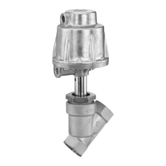
- Page 1 514 SKS Austausch des Ersatzteil-Sets SKS Replacement of spare parts kit SKS ORIGINAL MONTAGEANLEITUNG ASSEMBLY INSTRUCTIONS 514 SKS...
-
Page 2: Table Of Contents
(Wasserschläge) durch 6.3.3 Auswechseln des Ersatzteil-Sets 20 Schutzmaßnahmen vermeiden. Montage Montage Antriebsoberteil Einbau- und Montageanleitung 7.1.1 Steuerfunktion 1 GEMÜ 514 beachten! 7.1.2 Steuerfunktion 2 7.1.3 Steuerfunktion 3 Montage Antrieb auf Ventilkörper 24 7.2.1 Steuerfunktion 1 7.2.2 Steuerfunktion 2 / Steuerfunktion 3... -
Page 3: Bestelldaten
Teller PTFE glasfaserverstärkt Antrieb 5 Kolben ø 100 mm gegen den Teller Bei Verwendung von anderen Sitzdichtungen bitte Rücksprache mit GEMÜ halten Antrieb 3 Kolben ø 50 mm mit dem Teller Antrieb 4 Kolben ø 70 mm mit dem Teller... -
Page 4: Bestandteile Ersatzteil-Set Sks
V-Manschette 3 Stück) Packungsring (nur bei K-Nr. 2023) Druckring (bei Antriebsgröße 1: 3 Stück) (bei Antriebsgröße 2: 4 Stück) V-Manschette Packungsring (nur bei K-Nr. 2023) (bei Antriebsgröße 1: 3 Stück) (bei Antriebsgröße 2: 4 Stück) 514 SKS 4 / 52... - Page 5 Führungsbuchse Druckfeder Stützring V-Manschette (bei K-Nr. 2023, Antriebsgröße 1: 5 Stück) (bei K-Nr. 2023, Antriebsgröße 2: 3 Stück) Druckring V-Manschette Packungsring (nur bei K-Nr. 2023) (bei Antriebsgröße 1: 3 Stück) (bei Antriebsgröße 2: 4 Stück) 514 SKS 5 / 52...
-
Page 6: Steuerfunktion
Geräteaufbau Steuerfunktion 1 4.1.1 Geräteaufbau Steuerfunktion 1 Entlüftungs- bohrung Steuermedium- anschluss 2 Leckagebohrung Geräteaufbau GEMÜ 514 Steuerfunktion 1 514 SKS 6 / 52... -
Page 7: Komponenten Steuerfunktion 1
Führungsbuchse Druckfeder Stützring V-Manschette (bei K-Nr. 2023, Antriebsgröße 1: 5 Stück) (bei K-Nr. 2023, Antriebsgröße 2: 3 Stück) Druckring V-Manschette Packungsring (nur bei K-Nr. 2023) (bei Antriebsgröße 1: 3 Stück) (bei Antriebsgröße 2: 4 Stück) 514 SKS 7 / 52... -
Page 8: Steuerfunktion
Steuerfunktion 2 4.2.1 Geräteaufbau Steuerfunktion 2 Steuermedium- anschluss 4 Entlüftung Leckagebohrung Geräteaufbau GEMÜ 514 Steuerfunktion 2 514 SKS 8 / 52... -
Page 9: Komponenten Steuerfunktion 2
Führungsbuchse Druckfeder Stützring V-Manschette (bei K-Nr. 2023, Antriebsgröße 1: 5 Stück) (bei K-Nr. 2023, Antriebsgröße 2: 3 Stück) Druckring V-Manschette Packungsring (nur bei K-Nr. 2023) (bei Antriebsgröße 1: 3 Stück) (bei Antriebsgröße 2: 4 Stück) 514 SKS 9 / 52... -
Page 10: Steuerfunktion
Steuerfunktion 3 4.3.1 Geräteaufbau Steuerfunktion 3 Steuermedium- anschluss 4 Steuermedium- anschluss 2 Leckagebohrung Geräteaufbau GEMÜ 514 Steuerfunktion 3 514 SKS 10 / 52... -
Page 11: Komponenten Steuerfunktion 3
Führungsbuchse Druckfeder Stützring V-Manschette (bei K-Nr. 2023, Antriebsgröße 1: 5 Stück) (bei K-Nr. 2023, Antriebsgröße 2: 3 Stück) Druckring V-Manschette Packungsring (nur bei K-Nr. 2023) (bei Antriebsgröße 1: 3 Stück) (bei Antriebsgröße 2: 4 Stück) 514 SKS 11 / 52... -
Page 12: Demontage
(nur Originalteile von 3. Dichtring 4 entnehmen. GEMÜ verwenden). 1. Antrieb A in Off en-Position bringen. 2. Überwurfmutter a lösen. 3. Antrieb A vom Ventilkörper 1 entfernen. 4. Antrieb A von Steuermediumleitungen trennen. 5. Dichtring 4 entnehmen. 514 SKS 12 / 52... -
Page 13: Demontage Antriebsoberteil
Antriebsoberteil 10 und Antriebsunterteil 25 lösen und entfernen. 1. Antrieb A demontieren (siehe Kapitel 5.1 "Demontage Antrieb von Ventilkörper"). 2. Verschlussstopfen SA2 entfernen. 3. Anzeigespindel SA1 entfernen. 6. Presskraft langsam reduzieren. 7. Antriebsoberteil 10 entnehmen. 514 SKS 13 / 52... -
Page 14: Steuerfunktion 2
3. Antriebsoberteil 10 entnehmen. 2. Verbindungssschrauben 23 zwischen Antriebsoberteil 10 und Antriebsunterteil 25 lösen und entfernen. 4. Sechskantmutter 11 von der Spindel 2 3. Antriebsoberteil 10 entnehmen. lösen und entfernen. Druckfeder steht unter leichter Vorspannung! 514 SKS 14 / 52... -
Page 15: Auswechseln Des
Packungsring (nur bei K-Nr. 2023) (bei Antriebsgröße 1: 3 Stück) (bei Antriebsgröße 2: 4 Stück) Sechskantmutter Kolbenlaufbuchse Lippenring AD O-Ring O-Ring K-Nr. 2023 Lippenring ID Spindel Sitzdichtung Ventilteller Nietstift Tellerscheibe Die Spindel-Baugruppe wird schon komplett montiert ausgeliefert. Standardausführung 514 SKS 15 / 52... -
Page 16: Auswechseln Des Ersatzteil-Sets
Rohr im Antriebsunterteil 25 ziehen. Spindeloberfl äche nicht beschädigt, 14. Neue V-Manschetten vor Einbau mit festhalten). geeignetem Schmiermittel* fetten. 23. Neue Kolbenlaufbuchse 13 mit * GEMÜ empfi ehlt das Fett "Dow geeignetem Schmiermittel* fetten Corning 111 Molycote ® ". und in Antriebsoberteil 10 schieben 15. -
Page 17: Steuerfunktion 2
(bei Antriebsgröße 2: 4 Stück) Dichtring Sechskantmutter K-Nr. 2023 Kolbenlaufbuchse Lippenring AD O-Ring O-Ring (nur bei Antriebsgröße 2) O-Ring (nur bei Antriebsgröße 1) Spindel Sitzdichtung Ventilteller Nietstift Standardausführung Tellerscheibe Die Spindel-Baugruppe wird schon komplett montiert ausgeliefert. 514 SKS 17 / 52... -
Page 18: Auswechseln Des Ersatzteil-Sets
Antriebsoberteil 10 schieben V-Manschetten g und Druckring f) aus dem Rohr im Antriebsunterteil 25 ziehen. (Einbaulage beachten!). 12. Neue V-Manschetten vor Einbau mit * GEMÜ empfi ehlt das Fett "Dow geeignetem Schmiermittel* fetten. Corning 111 Molycote ® ". -
Page 19: Steuerfunktion 3
(bei Antriebsgröße 2: 4 Stück) Dichtring Sechskantmutter K-Nr. 2023 Kolbenlaufbuchse Lippenring AD (ab DN 50 2 Stück) O-Ring O-Ring Lippenring ID O-Ring (nur bei Antriebsgröße 1) Spindel Sitzdichtung Ventilteller Standardausführung Nietstift Tellerscheibe Die Spindel-Baugruppe wird schon komplett montiert ausgeliefert. 514 SKS 19 / 52... -
Page 20: Auswechseln Des Ersatzteil-Sets
Werkzeug, das die 15. Neue V-Manschetten vor Einbau mit Spindeloberfl äche nicht beschädigt, geeignetem Schmiermittel* fetten. festhalten). * GEMÜ empfi ehlt das Fett "Dow 25. Neuen O-Ring 44 in Antriebsoberteil 10 Corning 111 Molycote ® ". einlegen (nur bei Antriebsgröße 1). -
Page 21: Montage
Tabelle). Beschädigungen prüfen. Bei starkem Verschleiß müssen Antriebsoberteil 10 und Verbindungsschrauben 23 ausgetauscht werden (nur Originalteile von GEMÜ verwenden). 7.1.1 Steuerfunktion 1 1. Antriebsoberteil 10 auf Druckfedern 17, 18, 34 aufl egen und zentrieren. Die Anzahl der Druckfedern kann je nach Antriebsgröße und Nennweite variieren. -
Page 22: Steuerfunktion 2
Bohrung im Antriebskolben 20 zentrieren. Reihenfolge der Komponenten des Antriebskolbens beachten. Antriebsgröße Drehmomente Nm 3. (Neue) Sechskantmutter 11 auf die 0, 1, 3, 4 Spindel 2 schrauben. 4. Antriebsoberteil 10 auf Antriebsunterteil 25 aufl egen und zentrieren. 514 SKS 22 / 52... - Page 23 2. Auf Übereinstimmung der Lochbilder von Antriebsoberteil 10 und Antriebsunterteil 25 achten. 3. Antriebsoberteil 10 und Antriebsunterteil 25 mit Verbindungsschrauben 23 über Kreuz verschrauben (Drehmomente siehe Tabelle). Antriebsgröße Drehmomente Nm 0, 1, 3, 4 514 SKS 23 / 52...
-
Page 24: Montage Antrieb Auf Ventilkörper
3. Antrieb 360° drehbar. Position der Steuermediumanschlüsse beliebig. 4. Gewinde der Überwurfmutter a mit geeignetem Schmiermittel fetten. 5. Antrieb A auf Ventilkörper 1 ca. 90° vor Endposition der Steuermediumanschlüsse aufsetzen 6. Überwurfmutter a handfest in Ventilkörper 1 einschrauben. 514 SKS 24 / 52... -
Page 25: Steuerfunktion 2 / Steuerfunktion 3
Steuermediumanschlüsse beliebig. erten Medien achten. 4. Gewinde der Überwurfmutter a mit geeignetem Schmiermittel fetten. 5. Antrieb A auf Ventilkörper 1 ca. 90° vor Endposition der Steuermediumanschlüsse aufsetzen 6. Überwurfmutter a handfest in Ventilkörper 1 einschrauben. 514 SKS 25 / 52... - Page 26 6.3.1 Component kit avoid possible pressure surges (water 6.3.2 Exploded diagram hammer). 6.3.3 Replacement of the spare parts kit 44 Installation Observe the GEMÜ 514 Installation of actuator top installation, operating and 7.1.1 Control function 1 maintenance instructions! 7.1.2 Control function 2 7.1.3 Control function 3...
-
Page 27: Order Data
ø 120 mm under the seat PTFE glass fibre reinforced Actuator 5 piston dia. 100 mm under the seat Please consult GEMÜ before using other seats Actuator 3 piston dia. 50 mm over the seat Actuator 4 piston dia. 70 mm... -
Page 28: Components Of Spare Parts Kit Sks
Packing ring (only with K-no. 2023) Pressure ring (with actuator size 1: 3 pieces) (with actuator size 2: 4 Stück) Chevron packing Packing ring (only with K-no. 2023) (with actuator size 1: 3 pieces) (with actuator size 2: 4 Stück) 514 SKS 28 / 52... - Page 29 (with K-no. 2023, actuator size 1: 5 pieces) (with K-no. 2023, actuator size 2: 3 pieces) Pressure ring Chevron packing Packing ring (only with K-no. 2023) (with actuator size 1: 3 pieces) (with actuator size 2: 4 Stück) 514 SKS 29 / 52...
-
Page 30: Control Function 1
Construction Control function 1 4.1.1 Construction control function 1 Vent hole Control medium connector 2 Leak detection hole GEMÜ 514 Construction control function 1 514 SKS 30 / 52... -
Page 31: Components Control Function 1
(with K-no. 2023, actuator size 1: 5 pieces) (with K-no. 2023, actuator size 2: 3 pieces) Pressure ring Chevron packing Packing ring (only with K-no. 2023) (with actuator size 1: 3 pieces) (with actuator size 2: 4 Stück) 514 SKS 31 / 52... -
Page 32: Control Function
Control function 2 4.2.1 Construction control function 2 Control medium connector 4 Vent hole Leak detection hole GEMÜ 514 construction control function 2 514 SKS 32 / 52... -
Page 33: Components Control Function 2
(with K-no. 2023, actuator size 1: 5 pieces) (with K-no. 2023, actuator size 2: 3 pieces) Pressure ring Chevron packing Packing ring (only with K-no. 2023) (with actuator size 1: 3 pieces) (with actuator size 2: 4 Stück) 514 SKS 33 / 52... -
Page 34: Control Function 3
Control function 3 4.3.1 Construction control function 3 Control medium connector 4 Control medium connector 2 Leak detection hole GEMÜ 514 construction control function 3 514 SKS 34 / 52... -
Page 35: Components Control Function 3
(with K-no. 2023, actuator size 1: 5 pieces) (with K-no. 2023, actuator size 2: 3 pieces) Pressure ring Chevron packing Packing ring (only with K-no. 2023) (with actuator size 1: 3 pieces) (with actuator size 2: 4 Stück) 514 SKS 35 / 52... -
Page 36: Disassembly
(do not damage parts). Check parts for potential damage, replace if necessary (only Important: use genuine parts from GEMÜ). After disassembly, clean all parts 1. Disconnect the actuator A from control of contamination (do not damage medium lines. -
Page 37: Disassembly Of Actuator Top
After disassembly, clean all parts of contamination (do not damage parts). Check parts for potential damage, replace if necessary (only use genuine parts from GEMÜ). 1. Remove actuator A (see chapter 5.1 5. Undo and remove connecting bolts 23 "Disassembly of actuator from valve between actuator top 10 and actuator body"). -
Page 38: Control Function 2
3. Remove actuator top 10. between actuator top 10 and actuator base 25. 3. Remove actuator top 10. 4. Undo hexagon nut 11 on spindle 2 and remove it. The compression spring is slightly pretensioned. 514 SKS 38 / 52... -
Page 39: Replacement Of Spare Parts Kit Sks
(with actuator size 2: 4 Stück) Gasket Hexagon nut Piston sleeve Lip ring external sealing O-ring O-ring K-no. 2023 Lip ring internal sealing Spindle Seat seal Valve plug Retaining nut The spindle subassembly is supplied fully assembled. Standard version 514 SKS 39 / 52... -
Page 40: Replacement Of The Spare Parts Kit
14. Lubricate new chevron packings using 23. Lubricate new piston sleeve 13 using appropriate lubricant* prior to installation. appropriate lubricant* and push it into * GEMÜ recommends the lubricant "Dow actuator top 10 (pay attention to the ® Corning 111 Molycote ". -
Page 41: Control Function 2
K-no. 2023 Lip ring external sealing O-ring O-ring (only with actuator size 2) O-ring (only with actuator size 1) Spindle Seat seal Valve plug Retaining nut Standard version The spindle subassembly is supplied fully assembled. 514 SKS 41 / 52... -
Page 42: Replacement Of The Spare Parts Kit
10 (pay attention to the 12. Lubricate new chevron packings using installation position). appropriate lubricant* prior to installation. * GEMÜ recommends the lubricant "Dow * GEMÜ recommends the lubricant "Dow ® ® Corning 111 Molycote ". -
Page 43: Control Function 3
Lip ring external sealing (from DN 50, 2 pieces) O-ring O-ring Lip ring internal sealing O-ring (only with actuator size 1) Spindle Seat seal Valve plug Standard version Retaining nut The spindle subassembly is supplied fully assembled. 514 SKS 43 / 52... -
Page 44: Replacement Of The Spare Parts Kit
15. Lubricate new chevron packings using an appropriate tool that will not damage appropriate lubricant* prior to installation. the spindle surface). * GEMÜ recommends the lubricant "Dow 25. Insert new O-ring 44 in actuator top 10 Corning 111 Molycote ®... -
Page 45: Control Function 1
23 for potential damage. If they are heavily worn, actuator top 10 and connecting bolts 23 must be replaced (use only genuine parts from GEMÜ). 7.1.1 Control function 1 1. Place actuator top 10 onto compression springs 17, 18 and 34 and centre it. -
Page 46: Control Function 2
Observe the sequence of the piston components. Actuator size Torques Nm 3. Screw (new) hexagon nut 11 onto 0, 1, 3, 4 spindle 2. 4. Place actuator top 10 onto actuator base 25 and centre it. 514 SKS 46 / 52... -
Page 47: Control Function 1
5. Place actuator A on valve body 1 approx. 90° anticlockwise to the desired end position of the control medium connectors. 6. Screw union nut a into valve body 1 and tighten it until it is hand tight. 514 SKS 47 / 52... -
Page 48: Control Function 2 / Control Function
5. Place actuator A on valve body 1 approx. 90° anticlockwise to the desired end position of the control medium connectors. 6. Screw union nut a into valve body 1 and tighten it until it is hand tight. 514 SKS 48 / 52... -
Page 49: Disposal
Disposal Dispose of all parts in accordance with disposal regulations/environmental protection laws. Pay attention to adhered residual material and gas diff usion from penetrated media. 514 SKS 49 / 52... - Page 50 514 SKS 50 / 52...
- Page 51 514 SKS 51 / 52...
- Page 52 GEMÜ Gebr. Müller Apparatebau GmbH & Co. KG · Fritz-Müller-Str. 6-8 · D-74653 Ingelfi ngen-Criesbach Telefon +49(0)7940/123-0 · Telefax +49(0)7940/123-192 · info@gemue.de · www.gemu-group.com...