Table of Contents
Advertisement
Quick Links
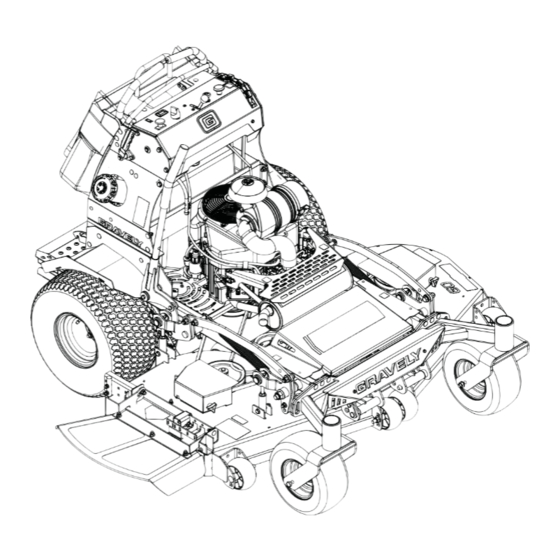
Pro-Stance
Manuel du Utilisateur
E10
Operator's Manual
ENGLISH
FRANÇAIS
®
Models
994132 – Pro-Stance 48
(SN 000101 +)
994133 – Pro-Stance 52
(SN 000101 +)
994134 – Pro-Stance 52
(SN 000101 +)
994135 – Pro-Stance 52 EFI
(SN 000101 +)
994137 – Pro-Stance 60
(SN 000101 +)
994138 – Pro-Stance 60 EFI
(SN 000101 +)
•
04897000A
1/16
Printed in USA
Advertisement
Table of Contents

Related Manuals for Gravely 994135


Summary of Contents for Gravely 994135
- Page 1 (SN 000101 +) 994133 – Pro-Stance 52 (SN 000101 +) 994134 – Pro-Stance 52 (SN 000101 +) 994135 – Pro-Stance 52 EFI (SN 000101 +) 994137 – Pro-Stance 60 (SN 000101 +) 994138 – Pro-Stance 60 EFI (SN 000101 +) ENGLISH •...
-
Page 2: Table Of Contents
TABLE OF CONTENTS WELCOME ..... . 2 ACCESSORIES....38 SAFETY. -
Page 3: Welcome
WELCOME Congratulations on your purchase and welcome to the Gravely family! Every machine in the Gravely lineup is designed for long-lasting and unsurpassed performance. We are confident your machine will be part of your family for many years to come. -
Page 4: Safety
REQUIRED OPERATOR SAFETY TRAINING The original purchaser of this unit was WARNING: This cutting machine is instructed by the seller on safe and proper capable of amputating hands and operation. If unit is to be used by someone feet and throwing objects. Failure other than the original purchaser, loaned, to observe the safety instructions rented, or sold, ALWAYS provide this manual... - Page 5 SAFETY DECALS AND 1. DANGER! LOCATIONS ALWAYS replace missing or damaged Safety Decals. See Figure 2 for safety decal WARNING! locations. Read Owner/Operator <20° Manual. Allow operation only by properly trained adult, never children. MAX. FILL Never direct discharge toward other people. Thrown objects can cause injury.
-
Page 6: Safety Rules
2. DANGER! 4. CAUTION! Discharge Hazard – NEVER direct discharge toward people, pets or property. CAUTION! Thrown objects can cause injury or damage. Dismemberment Hazard – Read Owner/Operator NEVER stick hands or feet Manual. Allow operation under deck or shielded only by properly trained areas. - Page 7 Improper use of power equipment can cause Never carry children, even with the blade(s) serious permanent injury or death to the shut off. They may fall off and be seriously operator or a bystander. injured or interfere with safe machine operation.
- Page 8 Check that operator’s presence controls, Always keep hands and feet away from all safety switches and shields are attached pinch points. and functioning properly. Do not operate Avoid slippery surfaces. Be sure of your unless they are functioning properly. footing while using pedestrian controlled Ensure Safety Interlock System is equipment, especially when backing up.
- Page 9 Disengage blade(s) when not mowing. Shut Watch for holes, ruts, bumps, rocks, or other off engine and wait for all parts to come to a hidden objects. Uneven terrain could complete stop before cleaning the machine, overturn the machine. Tall grass can hide removing the grass catcher, or unclogging obstacles.
- Page 10 DO NOT OVERFILL! This equipment and/or Fuel its engine may include evaporative To avoid personal injury or property damage, emissions control system components, use extreme care in handling gasoline. required to meet EPA and/or CARB Gasoline is extremely flammable and the regulations, that will only function properly vapors are explosive.
- Page 11 Explosive Gases from battery can cause Keep hands and feet away from moving death or serious injury. Poisonous battery parts. If possible, do not make adjustments fluid contains sulfuric acid and its contact with the engine running. with skin, eyes or clothing can cause severe Lower cutting deck unless a positive chemical burns.
-
Page 12: Setup
14. Check safety interlock system functions SETUP (see Safety Interlock System on page 12). WARNING: AVOID INJURY. Read WARNING: FAILURE OF and understand entire Safety section INTERLOCK together with before proceeding improper operation can result in severe personal injury. NOTICE: Refer to Controls and Features on page 11 during setup. -
Page 13: Controls And Features
17. Oil Pressure Light 5. Ignition Switch 18. Height-of-Cut (HOC) Index Wheel 6. Hour Meter 19. Malfunction Indicator Light (Models 994135, 138) 7. Throttle Lever 20. Deck Lift Pedal 8. Choke Control Knob (Models 994132, 133, 134, 137) 21. Speed Control Bar 9. -
Page 14: Operation
Perform the following tests to ensure the safety interlock system is working properly. If the unit does not perform as stated, contact your Gravely dealer for repairs. NOTICE: When the parking brake is engaged, the steering levers are locked in neutral. -
Page 15: Mower Lift And Height-Of-Cut (Hoc) System
When in the lock Malfunction Indicator Light position, the transport lock lever allows the Models 994135, 138 deck to automatically lock in the highest (5" (12.7 cm) HOC) position when the lift The fuel injection pedal is pushed fully downward. -
Page 16: Hour / Maintenance Meter
To disable this feature: Parking Brake Lever 1. Move transport lock knob up to the Off Engage parking brake; steering levers must position. lock in neutral. Disengage parking brake; engine must not Transport Transport start. Lock On Lock Off Release control lever; engine must turn off. 1. -
Page 17: Filling Fuel Tank
Service Alerts: Counts down hours until IMPORTANT: DO NOT OVERFILL! This service is needed and displays "Now" when equipment and/or its engine may include service id due. Service time is measured for: evaporative emissions control system components, required to meet EPA and/or •... -
Page 18: Starting And Shut Off
3. Check Engine Fuel and Crankcase Electronic Fuel Injection Models 994135, 138 Check and add fuel if required. Check that To start engines with fuel injection: engine crankcase oil is full. Follow engine 1. Move the steering levers to the neutral manual maintenance schedule. -
Page 19: Parking
2. With left steering control (OPC) TO PUSH THE UNIT depressed, release parking brake. Place the transaxles in bypass mode to move the unit with the engine off. See Figure 8. WARNING: Move the steering control levers slowly and keep the throttle control lever at slow speed until you learn how to operate the unit. -
Page 20: For Best Performance
To rotate platform down: FOR BEST PERFORMANCE 1. Stop unit, disengage PTO and wait for all • Cut grass when it is dry. moving parts to stop. • Keep mower blades sharp. 2. Engage parking brake. • Keep mower deck properly leveled. 3. -
Page 21: Maintenance Schedule
See Parking Brake Interlock System on page 12. Interlock System Check Hydraulic Fluid Check hydraulic oil level mark on expansion tank. Add 15W-50 synthetic motor oil (Gravely p/n 00057100) or equivalent as needed. Do not overfill. See Check Hydraulic Fluid Level on page 22. Check Tires See Specifications on page 38 for correct tire pressure. - Page 22 Period Service Task Clean Battery Keep battery and its terminals clean. See Clean Battery on page 25. Clean engine cooling Check and clean cooling fins and inside the engine system shrouds to remove grass, chaff or dirt. Every Check Fasteners Check mower blade mounting hardware and all other fasteners.
-
Page 23: Service And Adjustments
Gravely Dealers will provide any service which may be required to keep your unit operating at peak efficiency. Should engine service be required, it can be obtained from a Gravely Dealer or the engine manufacturer’s authorized service center. WARNING: AVOID INJURY. Read and understand entire Safety section before proceeding. - Page 24 75 hours of operation and then skin and result in serious injury or every 400 hours. Use 15W-50 synthetic death. motor oil (Gravely p/n 00057100) or Be sure to stop the engine before equivalent. doing any work on hydraulic parts.
-
Page 25: Mower Blades
9. Purge air from the hydraulic system. See MOWER BLADES Purging the Hydraulic System on See Figure 14. page 23. Remove CAUTION: Use sturdy gloves or padding to protect hands when working with mower blades. Rotation of one blade will rotate the other blades. - Page 26 Sharpen the Mower Blades IMPORTANT: When sharpening blades, be sure to grind the same amount on each side. See Figure 15. Unbalanced blades cause excessive vibration and could cause the spindles to CAUTION: DO NOT sharpen wear prematurely. mower blades while on unit. An unbalanced mower blade will 3.
-
Page 27: Fuse Block
FUSE BLOCK The fuse/relay panel is located behind the rear access panel, below the control panel. Fuse Block Diagram CONTROLS FUSE START/RUN RELAY RELAY CHARGING AUXILIARY FUSE FUSE TIME DELAY OPERATOR STARTER FUSE FUSE PRESENCE SOLENOID TIME DELAY RELAY RELAY ACCESSORY FUSE 07700114... -
Page 28: Transaxle Neutral Adjustment
25. steps 7 and 8. 10. Shut off engine. Jump-Starting 11. Replace drive wheels. Gravely does not recommend jump-starting your unit. Jump-starting can damage engine Axle Direction and electrical system components. See your engine manual for more detailed information. -
Page 29: Adjusting Unit To Track Straight
1. Eccentric Spacer 1. Tie Rod 2. Lock Nut 2. Eccentric Spacer 3. Eccentric Spacer Nut Figure 21 4. Jam Nut ADJUSTING UNIT TO TRACK Figure 20 STRAIGHT Steering Lever Interlock Adjustment Check and adjust tire pressure. Increase pressure on side unit tracks. DO NOT exceed See Figure 21. -
Page 30: Pto Belt
Adjust Parking Brake PTO Belt Access See Figure 22. 1. Properly stop, park, and turn off unit (see Operation on page 12). 1. Disengage parking brake. 2. Wait for unit to cool before accessing 2. Loosen jam nut on parking brake cable belts. - Page 31 6. Replace deck cover and belt guards on Replacing the Hydro Pump Belt deck. See Figure 25. 1. Properly stop and park unit (see Starting and Shut Off on page 16). 2. Using 1.3 cm (1/2") ratchet/breaker bar with an extension, extend the spring to relieve belt tension and remove the PTO belt from the mower clutch sheave (see Replacing Mower Belts on page 28).
-
Page 32: Mower Decks
1. Hydro Belt 2. Spring 3. Idler 4. Engine Sheave 1. Anti-scalp Rollers 5. Right Hand Hydrostat 2. Lowest Cutting Height 6. Left Hand Hydrostat 3. Highest Cutting Height 7. Clutch 8. Clutch Anchor Figure 26 9. Clutch Stop Deck Lift Assist Adjustment Figure 25 See Figure 27. -
Page 33: Hoc Indicator Adjustments
NOTICE: Lift springs must be adjusted to the same tension on each side of the deck to prevent cut quality issues. 1. Deck Lift Contact Arm 2. HOC Cam Figure 28 4. Rotate HOC wheel so the lowest cutting position (1.5 (38)) is indicated. Reset dial position if necessary. - Page 34 1. Outer Lock Nut 2. Inner Lock Nut 3. Belt Tensioner 4. HOC Belt Figure 29 Removing the Mower Deck See Figure 30. 1. Remove PTO belt (see Replacing Mower Belts on page 28). WARNING: AVOID INJURY. Mower lift arms and mower lift pedal could cause severe injury 1.
- Page 35 6. Level mower deck (see Leveling the NOTICE: Pitching the front of the blades Mower Deck on page 33). lower than the rear provides a balance between cut quality and the power needed to Leveling the Mower Deck cut grass. Certain cutting conditions require These adjustments should be made on a the deck to be pitched with the rear of the level surface with the tires inflated to the...
-
Page 36: Clutch Adjustment
4. Prepare fuel system for storage. • Maximum: A 0.051 mm (0.020") feeler gauge should slide between armature NOTICE: NOTICE: Gravely recommends and rotor with slight contact. using a quality fuel stabilizer in all fuel. Gasoline left in the fuel system without a 3. -
Page 37: Long-Term Storage
Clean and tighten battery cables. See Clean Battery on page 25. Discharged battery. Charge battery. See Charging the Battery on page 25. Faulty starter. See your Gravely Dealer. Engine does not Blown fuse. Check main fuse and replace if crank. necessary. - Page 38 Clean and tighten battery cables. See Clean Battery on page 25. Discharged battery. Charge battery. See Charging the Battery on page 25. Faulty starter. See your Gravely Dealer. Engine does not Blown fuse. Check main fuse and replace if crank. necessary.
- Page 39 ACCESSORIES SERVICE PARTS See your authorized Gravely dealer to add Be sure to always use genuine Gravely these optional accessories to your unit. parts to keep your unit running like new. Part No. Description Part No. Qty Description 79402400 Mulching Kit – 48"...
- Page 40 Tank Capacity – L (Gal) 34.1 (9) Transmission Type Hydrostatic Drive Transmission Oil Use 15W-50 synthetic motor oil (Gravely p/n 00057100) or equivalent Hydraulic Oil Filter Size and Weight Length – cm (in.) 155 (61 ) Width – cm (in.) Discharge Chute: Down 158.2 (62.3)
- Page 41 Tank Capacity – L (Gal) 34.1 (9) Transmission Type Hydrostatic Drive Transmission Oil Use 15W-50 synthetic motor oil (Gravely p/n 00057100) or equivalent Hydraulic Oil Filter Size and Weight Length – cm (in.) 157.5 (62) Width – cm (in.) Discharge Chute: Down 191.3 (75.3)
- Page 42 Equipment Limited Warranty Warranty Ariens Company (Ariens) warrants to the original purchaser that Ariens, Gravely and Countax brand products purchased on or after 9/1/2015 and designated or labeled commercial products by Ariens Company will be free from defects in material and workmanship for the time period noted in the chart below.
- Page 43 Exclusions – Items Not Covered by This Warranty • Parts that are not genuine Ariens, Gravely or Countax service parts are not covered by this warranty and may void the warranty. • Damages resulting from the installation or use of any part, accessory, or attachment which is not approved by the Ariens Company for use with product(s) identified herein are not covered by this warranty.
- Page 44 • Products are designed to the specifications in the area that the product was originally distributed. Different areas may have significantly different legal and design requirements. This warranty is limited to the requirements in the area in which the unit was originally distributed.
- Page 46 655 West Ryan Street Brillion, WI 54110 gravely.custhelp.com gravely.com...