Radio Shack 15-2506 - 1-4 Bi-Directional Cable-TV Amplifier Manual
- User manual (7 pages) ,
- User manual (2 pages)
Advertisement
Introduction
The RadioShack 1-4 Bi-Directional Cable-TV Amplifier is ideal for distributing a cable signal to a remote location. It can also distribute antenna and HDTV signals. This amplifier increases the output signal up to 8dB, while minimizing interference. It also allows bi-directional communication so you can enjoy pay-per-view events and interactive TV. It is also compatible with digital cable modems. The amplifier can be mounted on a wall or placed on a table or other indoor surface. You can cap off the unused outputs with the supplied terminators to reduce signal leakage.
Selecting a Location
Your amplifier should be placed close to your input source and an AC outlet. You can mount the amplifier on a wall or other surface using #6 screws (not supplied) suitable for mounting in your location.
- Do not place the amplifier outdoors.
- To keep exposed cable to a minimum, you can place the amplifier in your attic.
- To prevent interference, do not place the amplifier within six inches of any other electronic device.
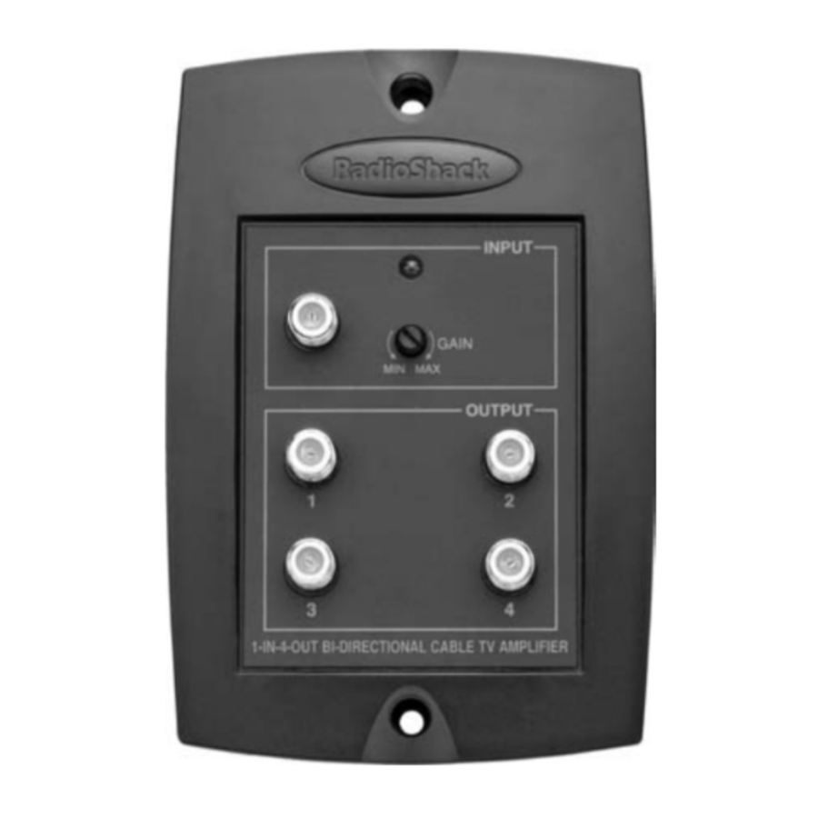
Front View

- INPUT — Connect a coaxial cable here to connect to your cable system or antenna.
- GAIN MIN/MAX — Adjust for the best TV picture quality.
- OUTPUT 1, 2, 3, 4 — Connect coaxial cables here to connect to up to four devices, such as a TV, cable modem, or HDTV.
- The red LED lights to indicate power is on.
Routing Cables
Route 75-ohm (RG-6 or RG-6QS) coaxial cable from the amplifier to your input source and to each receiver. Follow these hints when routing cable:
- Use only as much cable as necessary to reach from the amplifier to the input source and receivers.
- Do not route cables where they might be cut, crimped, or crushed by normal activities.
- For the best appearance, route cable through the attic and walls, and terminate each cable in a wall mount box with an F-connector. Wall mount F-connectors, coaxial cable, and other video accessories are available at your local RadioShack store.
Making Connections
- Connect a coaxial cable to your input source. To connect more than one input source, use a high isolation A/B switch or video selector to switch between inputs.
- Connect the coaxial cable from your cable box or antenna (input source) to the amplifier's INPUT terminal.

- Connect one end of the coaxial cable to an output device and the other end to an OUTPUT terminal.
- Attach supplied terminators to unused output terminals.
- Connect the supplied AC adapter to the jack on the amplifier.
- Plug the AC adapter into a standard AC outlet.
The amplifier's red LED lights when it has power. - Turn on every device connected to the amplifier.
- Use a flat-head screwdriver to adjust GAIN MIN/MAX until you get the best picture.

Safety Instructions
- Read and retain all the safety and operating instructions.
- This appliance should not be used near water, such as near a bathtub, washbowl, kitchen sink or laundry tub.
- This amplifier should be situated so that its location or position does not interfere with its proper ventilation.
- This amplifier should be connected only to a power supply of the type described in the operating instructions or as marked on the amplifier.
- Do not attempt to defeat the grounding or polarization components of this amplifier.
- Wipe the amplifier with a damp cloth occasionally to keep it looking new. Do not use harsh chemicals, cleaning solvents, or strong detergents to clean the amplifier.
- The power cord of the amplifier should be unplugged from the outlet when left unused for extended periods of time.
- Do not allow liquids to spill through the amplifier's openings.
- The amplifier should be situated away from heat sources such as radiators, heat registers, stoves or other appliances that cause heat. Temperature extremes can shorten the life of electronic devices and distort or melt plastic parts.
- If an outside antenna is connected to a receiver, be sure the antenna system is grounded to provide some protection against voltage surges, built-up static charges, and lightning strikes. Section 810 of the National Electric Code (NEC), ANSI/NFPA NO. 70-1990, provides information with respect to proper grounding of the mast and supporting structure, grounding of the lead-in wire to an antenna discharge unit, size of grounding conductors, location of antenna-discharge unit, connection to grounding electrodes, and requirements for the grounding electrode.
- The CATV system installers attention should be directed to Article 820-40 of the NEC that provides guidelines for proper grounding and, in particular, specifies that the cable ground shall be connected to the grounding system of the building, as close to the point of cable entry as practical.
- Do not use pliers to tighten screw-on F-connectors.
- Never connect both an outdoor antenna and the output from the amplifier to the antenna input of your TV or VCR without using a high isolation A/B switch. Doing so could cause interference with other nearby receivers.
- For an additional grounding method, remove a rubber foot from the amplifier and back out the #6 grounding screw. Place a grounding wire over the grounding screw and tighten the screw back into the housing.
- In extremely long cable runs (distances over 200 feet), additional amplification might be needed.
Specifications
| Forward Path | |
| Operating Frequency Range | 54–1000 MHz |
| Gain | up to 8dB |
| Gain Adjustment Range | 8dB |
| Reverse Path | |
| Operating Frequency Range | 5– 40 MHz |
| Insertion Loss | 8dB |
| Adapter Input Voltage | 105–135V |
| Power Usage | <2W |
| Power Line Frequency | 50–60 Hz |
| Dimensions (HWD) | 1 ½ × 3 ¾ × 5 ½-Inches (3.81 × 9.53 ×13.97 cm) |
| Weight | 7.36 oz (208.65 g) |
Specifications are typical; Individual units might vary. Specifications are subject to change and improvement without notice.

Documents / ResourcesDownload manual
Here you can download full pdf version of manual, it may contain additional safety instructions, warranty information, FCC rules, etc.
Download Radio Shack 15-2506 - 1-4 Bi-Directional Cable-TV Amplifier Manual
Advertisement
Thank you! Your question has been received!


Need Assistance?
Do you have a question about the 15-2506 that isn't answered in the manual? Leave your question here.