Raymarine C120 Installation Manual
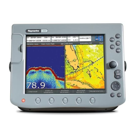
C-series display
Hide thumbs
Also See for C120:
- New features manual (54 pages) ,
- Operating manual (20 pages) ,
- Reference manual (244 pages)
Table of Contents
Advertisement
Advertisement
Table of Contents

Related Manuals for Raymarine C120


Summary of Contents for Raymarine C120
-
Page 1: Installation Manual
C-Series Display Installation Manual Document Number: 87020-3 Date: March 2006... -
Page 2: Trademarks And Registered Trademarks
Autohelm, HSB, Raymarine, RayTech, RayTech Navigator, Sail Pilot, SeaTalk and Sportpilot are registered trademarks of Raymarine Limited. Apelco is a registered trademark of Raymarine Holdings Limited (Registered in all major marketing territories). AST, Autoadapt, Auto GST, Autoseastate, Autotrim, Bidata, Marine... -
Page 3: Important Information
Intended use This handbook provides information and instructions to assist in planning and installing your Raymarine C-Series Display, together with information that will be useful when you are connecting the C-Series Display to other equipment. In order to obtain the best results in operation and performance, please read this handbook thoroughly. -
Page 4: Emc Conformance
EMC Conformance All Raymarine equipment and accessories are designed to the best industry standards for use in the recreational marine environment. The design and manufacture of Raymarine equipment and accessories conform to the appropriate Electromagnetic Compatibility (EMC) standards, but correct installation is required to ensure that performance is not compromised. -
Page 5: Handbook Information
Handbook information To the best of our knowledge, the information in this handbook was correct when it went to press. However, Raymarine cannot accept liability for an inaccuracies or omissions it may contain. In addition, our policy of continuous product improvement may change specifications without notice. - Page 6 C-Series Displays Installation Manual...
-
Page 7: Table Of Contents
1.1 General information ... 5 Contents of this pack ... 5 Dimensions ... 6 C70 Display ...6 C80 Display ...6 C120 Display ... 7 Accessories and spares ... 7 1.2 Planning the installation ... 8 EMC Installation Guidelines ... 8 Suppression Ferrites ... 9 Where should the Display unit be located? ... - Page 8 Test and align the radar ...37 Radar transmission check ...37 Radar alignment checks ...38 Adjusting the bearing alignment ...39 Checking the GPS ...39 Checking heading data ...40 Checking the Chart application ...40 Testing the Fishfinder application ...41 Setting the NMEA for AIS or Navtex ...41 Testing instrument data ...42...
- Page 9 Chapter 5: Troubleshooting ...45 5.1 How can I troubleshoot my Display? ...45 5.2 Technical Support ...46 World wide web ...46 Help us to help you ...46 Contacting Raymarine in the US ...47 Accessories and parts ...47 Product repair and service ...47...
- Page 10 C-Series Displays Installation Manual...
-
Page 11: Chapter 1: Preparation For Installation
Chapter 1: Preparation for installation 1.1 General information Contents of this pack The C-Series (C70, C80 or C120) Display pack contains the following items: Item C-Series Display Display Bezel Trunnion Bracket Trunnion Bracket knobs Panel mounting seal Sun cover Trim ring Power Cable (1.5m) -
Page 12: Dimensions
Dimensions The dimensions for your C-Series display are: C70 Display 253 mm (10 in) 282 mm (11.1 in) C80 Display 283 mm (11.14 in) 312 mm (12.3 in) PAGE ACTIVE WPTS DATA MENU RANGE CANCEL 9.5 mm (0.375 in) 89.4 mm (3.5 in) PAGE ACTIVE... -
Page 13: C120 Display
Raymarine accessories and parts can be obtained from your authorized Raymarine dealer. However, if you are in need of an item not available from the retailer or you are uncertain what item to choose for your Display, please contact Raymarine direct (see page 46 ). -
Page 14: Planning The Installation
This will not damage the equipment, but may cause the loss of some infor- mation and may change the operating mode. • Raymarine specified cables are used. Cutting and rejoining these cables can com- promise EMC performance and must be avoided unless doing so is detailed in the installation manual. -
Page 15: Suppression Ferrites
Suppression Ferrites Connections to other equipment If your Raymarine equipment is to be connected to other equipment using a cable not supplied by Raymarine, a suppression ferrite MUST always be attached to the cable near to the Raymarine unit. Where should the Display unit be located? Your C-Series display can either be flush-mounted or mounted using the trunnion bracket supplied. - Page 16 C-Series Displays Installation Manual...
-
Page 17: Chapter 2: System Integration
SeaTalk SeaTalk is an enhanced replacement for SeaTalk and is a proprietary extension to NMEA 2000 and the proven CAN bus technology. It enables other Raymarine SeaTalk devices to talk to each other, whilst maintaining near transparent NMEA 2000 compatibility. -
Page 18: What Is Nmea
Pathfinder Radar Scanner Handbook, Document No. 81154_8, dated 12th January 2005. To achieve full radar compatibility with your C-Series Display, your Raymarine radar scanner may require upgrading. Please check the list below to see if this upgrade is required. -
Page 19: Digital Sounder Module
4Kw Radome - RD424 4Kw Open Array 10Kw Open Array The Open Array system will also require a split pedestal cable. If your radar scanner requires upgrading, please contact your local Raymarine dealer for full information. Digital Sounder Module Important: Your Digital Sounder Module (DSM) should be C-Series compliant as indicated on the packaging. -
Page 20: Compactflash Cards
Compatible engine data AIS receiver For full details of scanner compatibility see page 13. If you are still unsure as to Notes: (1) your scanner’s suitability, please refer to an authorized Raymarine dealer. ® CF memory cards are used. Application/function ✔... - Page 21 Engine output from a compatible engine manufacturer is also required. See Raymarine.com for latest compatibility information. Whilst an AIS receiver is not required for the radar and chart applications to function, this receiver is necessary if AIS functionality is required within radar and chart.
-
Page 22: How Is The C-Series Display Integrated
2.5 How is the C-Series display integrated? The diagrams that follow show some suggested set ups. These are not however the only possible combinations. SeaTalk system Radar DSM 250 or 300 In this system: • C-Series powers SeaTalk for an alpha numeric keypad and RS120. •... -
Page 23: Integrated System1
• SeaTalk bus must remain powered when C-Series is off so that the radio continues to receive GPS data. • Open arrays must be powered using the split cable. • AIS or Navtex receiver connected via NMEA 0183 cable Open Array Power IN (12v or 24v) C120 PAGE ACTIVE WPTS/ DATA MENU RANGE... -
Page 24: Integrated System 2
• Smart heading sensor provides fast heading data for MARPA and radar overlay. • Autopilot provides power for SeaTalk. Open Array: 4 ft, 4kW - 12v/24v 6 ft, 10kW - 24v Power IN (12v or 24v) C120 PAGE ACTIVE WPTS/ DATA MENU RANGE... -
Page 25: Integrated System 3
Note: If you select the depth data box it will show SeaTalk transducer depth. In this system the course computer with rate gyro will provide fast heading for radar overlay and MARPA. Open Array Power IN (12v or 24v) C120 PAGE ACTIVE WPTS/ DATA MENU... - Page 26 C-Series Displays Installation Manual...
-
Page 27: Chapter 3: Installation
Chapter 3: Installation CAUTION: Preparation Please ensure that you have read ‘Preparation for Installation before proceeding. CAUTION: Radar Scanners, Cables & Installation Information on radar scanners, cables and their installation contained in this handbook supersedes that contained in the Pathfinder Radar Scanner Handbook, Document No. -
Page 28: Flush Mount
1. Check the selected location for the unit. A clear, flat area with suitable clearance behind the panel, is required. 2. Fix the appropriate template - C70, C80 or C120, supplied in the document wallet, to the selected location, using masking or self-adhesive tape. - Page 29 3. Using a suitable hole saw (the size is indicated on the template), make a pilot hole in each corner of the cut-out area. 4. Using a suitable saw, cut along the inside edge of the cut-out line. 5. Ensure that the unit fits into the removed area and then file around the cut edge until smooth.
-
Page 30: Attaching The Front Bezel
Fixing bolts When console mounting your C-Series Display, avoid damaging the rear trim ring by using the correct length bolts. The length used is dependant upon bulkhead thickness: Bulkhead Thickness (mm) 7-11 11-15 15-19 19-23 Attaching the front bezel After you have installed the C-Series Display in the required position, you should attach the front bezel as follows: 1. -
Page 31: Removing The Front Bezel
2. Place the bezel over the front of the C-Series Display, ensuring that locking lugs located at the bottom edge of the bezel are latched into position. 3. Ensure that the control buttons pass through their respective openings. 4. Apply firm but even pressure to the bezel along the: •... -
Page 32: Cables
3. Working from this corner, free the clips along the top edge of the display, then work towards the bottom edge. Taking care to ensure that the control buttons pass through the bezel. DO NOT lever along the top edge. 4. -
Page 33: Using Cable Splicers
C-Series cable connections Power (1.5m) Supplied Not supplied/accessory Using cable splicers The cable splicers are used to make the connections from the SeaTalk/Alarm out and NMEA 0183 cables easy and secure, without removing insulation from cable tails. Do not use cable splicers on any cables other than SeaTalk/Alarm out and NMEA 0183. Note: To use these connectors: SeaTalk... -
Page 34: Extension Cable
12v or 24v. The power connection should be made at either the output of the battery isolating switch, or at a DC power distribution panel. Raymarine recommends that power is fed directly to the display and scanner via its own dedicated cable system and MUST be protected by a thermal circuit breaker or fuse, installed close to the power connection. -
Page 35: Seatalk Cable
Fuse, circuit breaker and switch ratings Radar scanner? SeaTalk cable The SeaTalk cable is supplied with stripped tails. These should be connected to your existing equipment using either the cable splicers supplied or by using a standard screw terminal block. Yellow (+12V) Drain (Screen) NMEA 0183 cable... -
Page 36: Fishfinder Cable
Fishfinder cable The fishfinder cable is supplied with your Digital Sounder Module (DSM). This cable should be run and connected to the rear of the display. DSM 250 A terminator must be fitted to the cable at the DSM 250: •... -
Page 37: Connecting To An Open Array
If the existing cable is too short, please order from the following: Part No. Cable length E55065 E55066 E55067 E55068 Radome inter-unit cable for use with the C Series display To display or extension (power supplied via display unit) Connecting to an open array If you are using an open array, this cannot be powered through the display. - Page 38 (12/24V) Black (0V) Green Connect to (ground) boat's DC power supply The split pedestal cables are available from your local Raymarine dealer as follows: Part No E05017 E05018 E05019 ... to replace a Raymarine Pathfinder Display Part No Description...
- Page 39 Split pedestal cable To display Note: You should ensure that the distance (cable route) from the power supply to the open array is kept to a minimum. To power To Open Array Scanner D7209-1...
- Page 40 C-Series Displays Installation Manual...
-
Page 41: Chapter 4: Commissioning The System
Chapter 4: Commissioning the system 4.1 Introduction This chapter details the commissioning of your C-Series Display and includes the following: • Required input. • Pre-start checks. • Initial power on procedure • Radar checks and alignment. • Chart application checks. •... -
Page 42: Initial Power On Procedure
Check that the GPS has a clear view of the sky and is not obstructed e.g. by buildings, bridges or other equipment fitted on-board. Other equipment For details of pre-start checks for other equipment e.g. AIS and Navtex receivers, please refer to the relevant handbook. -
Page 43: Tests And Checks
4.4 Tests and checks Test and align the radar Your C-Series display is part of an integrated system. Raymarine strongly advise that you test and align the radar before connecting to other systems. To test and align the radar you must first select a radar application. With the Select Page Set screen displayed (see previous section): 1. -
Page 44: Radar Alignment Checks
Radar alignment checks You should check the bearing and display timing alignment to ensure that an accurate picture is shown. Bearing alignment Adjusting the bearing alignment ensures that targets appear at the correct bearing relative to your boat’s bow. You need to select a visible target of known bearing that is displayed on the radar, and then adjust the radar set up as necessary until the correct bearing reading is obtained. -
Page 45: Adjusting The Bearing Alignment
8. To exit the menu, press OK or CANCEL. Checking the GPS The GPS is used to position your boat on the chart. You can set up your Global Positioning System (GPS) and check its status using the GPS status icons and the GPS Status page of the Setup menu. -
Page 46: Checking Heading Data
The option to select differential or satellite differential fix is dependent upon the capabilities of the attached GPS. If your boat is equipped with a Raymarine GPS, the Differential GPS can be switched on or off using the appropriate soft key. -
Page 47: Testing The Fishfinder Application
3. Zoom out with the RANGE button until the world map is visible. 4. To ensure that the display is responding to position data: i. Press FIND SHIP. ii. Check that the cursor is positioned over the boat symbol in the centre of the dis- play. -
Page 48: Testing Instrument Data
• A VHF antenna (part of an AIS system). • A GPS. • A Compass - although not essential, this will enhance performance. When the AIS unit is connected to the C-Series display, the status of the unit is indicated by an AIS icon in the transducer data box. -
Page 49: Advanced Settings
AIS unit not available i.e. not connected or off. AIS unit switched on and operating. AIS unit on with active alarm. AIS unit switched on and operating but dangerous & lost target alarm disabled. 4.5 Advanced Settings The Advanced Set Up features allow you to set the values for the following parameters that affect the fine tuning of your radar: Parameters Display timing... -
Page 50: Display Timing
C-Series Displays Installation Manual Display timing The display timing can be affected by the length of cable used to connect the scanner to your C-Series display. This will in turn affect the short range accuracy of the radar. A symptom of incorrect timing is that bridges or piers shown on the picture appear to be bowed i.e. -
Page 51: Chapter 5: Troubleshooting
• Check your boat’s power supply for faulty connections or insufficient cable diameter. How do I upgrade my Display software? Visit www.raymarine.com and click on Support to download the latest software. Follow the instruc- tions included with these downloads. How do I reset my display? Via the system setup menu. -
Page 52: Technical Support
For fastest support - 24 hours a day, seven days a week; go to the Frequently Asked Questions section. Most questions are answered here. The website will also give you servicing information, e-mail access to the Raymarine Technical Support Department and details of the locations of Raymarine agents, worldwide. -
Page 53: Contacting Raymarine In The Us
Contacting Raymarine in the US You can contact Raymarine in the US either using the Raymarine world wide web as detailed above or by calling one of the telephone numbers below. Accessories and parts You can obtain many Raymarine accessories and parts directly from your authorized Raymarine dealer. - Page 54 C-Series Displays Installation Manual...