Raymarine C Series Reference Manual
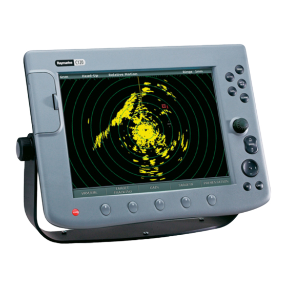
C series lcd color displays
Hide thumbs
Also See for C Series:
- Reference manual (180 pages) ,
- Installation manual (64 pages) ,
- Operating manual (20 pages)
Table of Contents
Advertisement
Advertisement
Table of Contents
Troubleshooting

Related Manuals for Raymarine C Series


Summary of Contents for Raymarine C Series
- Page 1 C-Series Display Reference Manual Document number: 81221_4 Date: March 2006...
-
Page 2: Trademarks And Registered Trademarks
Trademarks and registered trademarks Autohelm, HSB, Raymarine, RayTech Navigator, Sail Pilot, SeaTalk and Sportpilot are registered trademarks of Raymarine Limited. Apelco is a registered trademark of Raymarine Holdings Limited (registered in all major marketing territories). AST, Autoadapt, Auto GST, Autoseastate, Autotrim, Bidata, Marine Intelligence, Maxiview, On Board, Raychart, Raynav, Raypilot, Raystar, ST40, ST60, Seaclutter, Smart Route, Tridata and Waypoint Navigation are trademarks of Raymarine Limited. -
Page 3: Important Information
Important Information Intended use The display units detailed in this handbook may form part of marine navigational radar system or GPS system intended for use on (non-IMO/SOLAS class) leisure vessels or small workboats. This handbook contains important information on the operation and maintenance of your C-Series Display. - Page 4 The C-Series and its charts do not therefore exclude the user from carrying the required official charts and documents. Raymarine does not warrant that this product is error-free or that it is compatible with products manufactured by any person or entity other than Raymarine.
-
Page 5: About This Manual
Technical accuracy To the best of our knowledge, the technical information contained within this handbook, was correct at the time of printing. However, Raymarine cannot accept liability for any inaccuracies or omissions it may contain. In addition, Raymarine’s policy of continuous product improvement may change specifications without notice. - Page 6 Outside of North America, contact your local dealer or Navionics SpA on: Phone: (+39) 0584 961696 or Fax: (+39) 0584 961309) When archiving data, Raymarine recommends that you only use SanDisk CF memory cards. Other brands of CF memory card may not work in your C-Series Display.
-
Page 7: Table Of Contents
Contents Chapter 1: Overview ...1 1.1 What will my C-Series integrate with? ... 1 1.2 What can the C-Series Display do? ... 2 1.3 The Simulator ... 4 Chapter 2: General Operation ...5 2.1 Introduction ... 5 2.2 Powering the display ON/OFF ...5 2.3 Using the controls ...6 The control panel ... - Page 8 Chapter 3: Working with Waypoints ...29 3.1 What is a waypoint? ...29 3.2 How are waypoints represented? ...30 3.3 Placing a waypoint ...31 3.4 Navigating to a waypoint ...32 Start navigating to a waypoint ...32 Stop navigating to a waypoint ...33 3.5 Viewing waypoint information ...33 3.6 Editing a waypoint ...34 Changing waypoint details ...35...
- Page 9 Displaying details of objects and features ...48 Finding nearby features and services ...48 Displaying details of tides ...49 Displaying details of currents ...50 Displaying details of port services ...50 Displaying details of business services & points of interest ...53 Displaying vessel identity (AIS) ...54 4.8 Measuring distances and bearings ...55 ...
- Page 10 Creating a track ...79 Creating a route from a track ...80 4.16 Editing tracks ...81 Selecting a track for editing ...81 Editing the selected track ...82 4.17 Defining how the chart windows are presented ...83 Working with multiple chart views ...83 Setting the orientation of the chart ...84 Setting the motion mode ...85 4.18 Altering the level of chart detail displayed ...86...
- Page 11 5.8 Setting up your fishfinder ...110 Display settings ...111 Transducer Calibration ...112 DSM Setup ...113 5.9 Other settings affecting the fishfinder image ...114 Operating frequency modes ...114 Gain modes ...115 Adjusting the power setting ...117 Chapter 6: Using the Radar ...119 6.1 Introduction ...119 6.2 What is radar? ...119 Detecting targets ...119...
- Page 12 Acquiring a target to track ...147 Cancelling targets ...147 Displaying vessel identity (AIS) ...148 6.11 Setting up your radar ...148 6.12 Warnings of potential dangers ...150 Chapter 7: Using the data application ...151 7.1 Introduction ...151 7.2 Selecting a data application ...151 7.3 Selecting the data for display ...152 Pre-configured data panels ...152 Customize the panels ...153...
- Page 13 Chapter 11: Automatic Identification System (AIS) ...167 11.1 Introduction ...167 11.2 What is AIS? ...167 Classes of AIS data ...167 11.3 What do I need to run AIS? ...169 11.4 Selecting the AIS function ...169 AIS status ...169 11.5 How is AIS data displayed? ...170 AIS Target symbols ...170 Viewing target information ...171 11.6 Using AIS for collision avoidance ...173...
- Page 14 13.4 Troubleshooting your Display ...195 Common problems and how to solve them ...195 13.5 Getting Technical Support ...198 World wide web ...199 Contacting Raymarine in the US ...199 Contacting Raymarine in Europe ...200 For Navionics cartography ...201 AppendixA: Specification ... 203 AppendixB: List of Abbreviations ...
-
Page 15: Chapter 1: Overview
Chapter 1: Overview This chapter gives an overview of the C-Series display system and its features. 1.1 What will my C-Series integrate with? Autopilot Remote keyboard Fishfinder DSM 250 When used as part of a SeaTalk system it will display information from other SeaTalk and NMEA instruments. -
Page 16: What Can The C-Series Display Do
1.2 What can the C-Series Display do? With the appropriate equipment connected to your system and the necessary data available, your C-Series display combines the following applications which are used to: Chart (Chapter 4) 0.5nm North-Up (Relative Motion) You will need a chart card, and position/heading data, for the chart application to be fully functional. - Page 17 Data (Chapter 7) Course Deviation Indicator (Chapter 8) North-Up Relative Motion You will need accurate heading and position data for your CDI application to be fully functional. Engine Monitor (Chapter 9) Navtex (Chapter 10) Major areas of NAVTEX coverage include the Mediterranean Sea, the North Sea, coastal areas around Japan and areas around the North American continent.
-
Page 18: The Simulator
Waypoints (Chapter 3) & AIS (Chapter 11) Whilst not applications in their own right, waypoints and AIS are handled at system level and are covered in separate chapters. 1.3 The Simulator The C-Series Display includes a simulator mode, which allows you to practice operating your display without data from a GPS antenna, radar scanner, fishfinder or AIS receiver. -
Page 19: Chapter 2: General Operation
Chapter 2: General Operation 2.1 Introduction This chapter gives details of the general operation of the C-Series display, and covers the following subjects: • Powering the display on/off. • Using the controls. • Application display. • Displaying and editing additional information. •... -
Page 20: Using The Controls
2.3 Using the controls The control panel DATA ACTIVE Press to access When multiple windows are open: ruler, chart vectors, - Press to select required window. archive & transfer - Press and hold to maximise current and data bar window. on/off functions. -
Page 21: Buttons And Soft Keys
Buttons and soft keys To navigate to the required function you will need to press a series of buttons and/or soft keys: Buttons Access system functions or change what you see on-screen. Within the text of this document they are written in bold capitals e.g. -
Page 22: The Cursor
The cursor When you are using the chart and radar applications, the cursor is used to move around the screen: The cursor appears on the screen as a white cross. If the cursor has not been moved for a short period of time, it changes to a circle with a cross in it, to make it easier to locate on the screen. -
Page 23: Additional Screen Information
2.5 Additional screen information Information is displayed on the screen using a variety of methods: Status bar Status bar Gives information specific to Gives information specific to each application. each application. Cannot be edited or moved. Cannot be edited or moved. Head-Up Head-Up Data base lists... - Page 24 Menus Menus enable you to configure your system to your particular needs. Whenever the MENU button is pressed, the Setup menu is displayed MENU MENU containing a list of all the menus available for the active application D6582-1 together with system wide menus e.g. Menus for the active application External equipment/...
- Page 25 Editing the dialog box information Dialog boxes enable data to be edited or entered into a list e.g. Edit Waypoint screen. To edit/enter data into a dialog box: 1. Select the field for editing: e.g. Symbol Name Waypoint 1 My Waypoints Group Comment Highlight field to be edited...
-
Page 26: Status Icons
The satellite icon indicates the current status of your GPS: FIX - your unit is successfully connected to a GPS receiver. NO FIX - your unit has been unable to connect to a suitable GPS receiver. (static icon) The scanner icon indicates the current status of your radar scanner: Icon rotates - the scanner is transmitting (TRANSMIT/TX mode). -
Page 27: Initial Setup Procedures
2.6 Initial setup procedures When you first use your C-Series Display after it has been commissioned (see Installation Guide), we recommend that you carry out the following: • Set the language, the date and time format and preferred units of measurement. •... -
Page 28: Selecting A Page Set
Selecting a page set Your Display has four pre-configured page sets and one empty set for you to choose from. PAGE Press & hold Note: Alternatively, you can access the Select Page Set screen via MENU. If none of the pre-configured page sets meet your particular requirements and/or you intend to use the engine monitor application, refer to the Setup and Customizing chapter for details of how to customize both the layout and the application appearing in each window. -
Page 29: Selecting An Application Window
Selecting an application window When the selected page has more than one window, the window that is currently active will be bordered in red e.g. Changing the active window To change the active highlight to other windows on the page and display the associated soft keys: e.g. -
Page 30: Adjusting The Display Lighting
C-Series Display Reference Manual Adjusting the display lighting The display has two distinct color palettes, for day and night operation. You can also manually adjust the backlight level. Note: The display lighting is a local setting and will therefore only affect the individual display on which you are working. -
Page 31: Using Compactflash Cards
2.7 Using CompactFlash cards Cautions CAUTION: CompactFlash Card Installation When installing CompactFlash cards ensure that the card is fitted the correct way around. DO NOT try to force the card into position as this may result in irreparable damage to the card. CAUTION: Water Ingress To prevent the ingress of water and consequent damage to the display, ensure that the chart card door is firmly closed at all times. -
Page 32: Inserting A Card
Inserting a card To insert a card, refer to the illustration and: 1. Check that you are using the correct type of card (see beginning of this manual 2. Open the chart card door, located on the front left of the display. 3. -
Page 33: Managing Data
PC, SeaTalk and NMEA instruments (see Saving information to a card Important: Raymarine strongly recommend that you save data to a separate CompactFlash card and not to a Navionics card containing cartography. 1. Insert card and select the SAVE TO CARD function:... - Page 34 2. Select list containing data for saving: SELECT LIST WPT RTE TRK Toggle to required list 3. Define data for saving To save all items in list to card: SAVE ALL To save individual items: e.g. ROUTE LIST Route 1 Route 2 Route 3 Highlight item...
- Page 35 To retrieve all selected database items: RETRIEVE ALL To retrieve individual items: e.g. ROUTE LIST Route 1 Route 2 Route 3 Highlight item for retrieving If whilst retrieving information a selection is already found to exist on the system, a warning message will appear.
-
Page 36: Sending And Receiving Information Using A Pc
To delete all items: ERASE ALL To delete individual items: e.g. ROUTE LIST Route 1 Route 2 Route 3 Highlight item for deleting Sending and receiving information using a PC You can transfer and retrieve waypoints or routes to and from another instrument or PC using NMEA. -
Page 37: Password Protecting Your Waypoints
Password protecting your waypoints If required, you can prevent access to, modification and sight of your waypoint and route databases and functions by means of a password. Password confirmation When Password Protection is enabled and you are attempting to access a password protected function for the first time during a power-cycle, the system will request confirmation of your password before you can: •... - Page 38 Setting Password Protection required a password to access your waypoint and route databases. If you forget your password you will lose your waypoints and routes Raymarine recommends that you archive your waypoints and routes Read and accept the warning e.g. Edit Password...
- Page 39 Settings page 184 and Data Reset (see Raymarine strongly recommend therefore that you regularly back-up your waypoints, routes and tracks to a CF memory card. System Setup Menu...
-
Page 40: Emergencies And Warnings
(MOB symbol) and your on-screen vessel. • Other equipment - other Raymarine equipment acknowledges the MOB. • Current position to MOB position - as your vessel moves away from the MOB position, a dotted line is displayed from your current position to the MOB position. -
Page 41: Silencing And Clearing Mob
Silencing a MOB To temporarily silence the alarm from a MOB, press any key on any instrument on the SeaTalk system. After approximately 10 seconds the alarm will sound once more if the state of MOB is still active. Silencing an alarm will not deactivate or clear the MOB state. Clearing a MOB To clear a MOB and its data: Alarms... -
Page 42: C-Series Display Reference Manual
C-Series Display Reference Manual... -
Page 43: Chapter 3: Working With Waypoints
Chapter 3: Working with Waypoints This chapter gives details of how to place, edit, manage and navigate to a waypoint. 3.1 What is a waypoint? A waypoint is a position marked on a chart, radar or fishfinder window to indicate a site (for fishing, diving etc.) or as a place to navigate to. -
Page 44: How Are Waypoints Represented
3.2 How are waypoints represented? Waypoints on Chart and Radar windows On chart and radar windows, a waypoint is represented when it is both active (displayed in a box) and inactive (no box) i.e. Default waypoint Waypoints on CDI windows On CDI windows, a waypoint is represented only when it is active (displayed in a box). -
Page 45: Placing A Waypoint
3.3 Placing a waypoint A waypoint can be placed at: • The cursor position. • Your vessel’s position. • At a position of your choosing (using lat/lon or Loran TD coordinates between 80 N/S). When you are placing a waypoint, you can either accept the default or customize its details. -
Page 46: Navigating To A Waypoint
3.4 Navigating to a waypoint This section explains how to start and stop navigating to a waypoint. When you navigate to a waypoint or to the cursor position, the data is sent on NMEA 0183 and SeaTalk and can be used by an autopilot, if connected. For more information on navigation, see Start navigating to a waypoint ...using the cursor... -
Page 47: Stop Navigating To A Waypoint
Stop navigating to a waypoint If at any time you wish to stop navigating towards the selected waypoint: WPTS/ WPTS/ Position cursor over active waypoint. Once navigation is no longer active, the waypoint symbol returns to its normal unboxed state and the dashed line between your boat and the waypoint is removed. 3.5 Viewing waypoint information You can view the details of any waypoint that you have placed, by either selecting it with the cursor (in radar and chart windows) or by selecting it on the waypoint list. -
Page 48: Editing A Waypoint
To access the waypoint list: WPTS/ 3.6 Editing a waypoint Once a waypoint has been placed it can be edited in a variety of ways. You can: • Change the waypoint details - name, symbol, group or add a comment. •... -
Page 49: Changing Waypoint Details
Changing waypoint details When a waypoint is created it is assigned a default name, symbol and group. You can change these details to suit your needs and add a comment if required. This is particularly useful when you are managing large numbers of waypoints. To change the details of a waypoint: 1. -
Page 50: Erasing A Waypoint(S)
CAUTION: It is possible to move waypoints that are used in routes. In such instances, the stored route will include the Waypoint in its new position. Ensure that this does not present a navigation hazard. Erasing a waypoint(s) You can erase any waypoint on the system (including groups of waypoints) except: •... -
Page 51: Changing The Default Symbol Or Group
Erasing all waypoints If you need to erase all your waypoints, you can use the ARCHIVE & TRANSFER soft keys: 1. Select the ERASE FROM SYSTEM and the appropriate list: ARCHIVE AND DATA TRANSFER 2. Erase all waypoints: System Waypoint List Waypoint Group 1 Waypoint Group 2 Waypoint Group 3... -
Page 52: Sorting The Waypoint List
Group To abandon the symbol or group default change, press CANCEL. Note: 3.7 Sorting the waypoint list If your system contains a large number of waypoints, you can sort your waypoint list to make it easier to locate a particular waypoint. The waypoint list can be sorted by: •... -
Page 53: Making A New Waypoint Group
WPTS/ REVIEW AND EDIT WAYPOINTS ... You can now make a new waypoint group, or erase, move or rename existing groups. Making a new waypoint group To create a new waypoint group: 1. Display the group list (see above). 2. You can now either: Make a new group and accept the default name: MAKE NEW GROUP... -
Page 54: Renaming An Existing Group
4. Determine the group that the waypoint is to be moved to: GROUP LIST MOVE BETWEEN GROUPS GROUP A GROUP B My Waypoints Fishing Waypoint 1 Waypoint 2 Waypoint 3 Move control to Group B 5. Select waypoint to be moved: MOVE BETWEEN GROUPS GROUP A My Waypoints... -
Page 55: Erasing A Group
Erasing a group You can erase any waypoint group from the system except the group containing the active waypoint. When a waypoint group is erased, the group name together with all of the waypoints in that group are erased from the system with the exception of: •... -
Page 56: Showing/Hiding Waypoint Symbols
Showing/hiding waypoint symbols You can define which waypoint symbol types are shown/hidden in the radar or chart application: 1. Display the SHOW BY SYMBOL option: PRESENTATION... 2. To change the status (show or hide) of a symbol type: SHOW BY SYMBOL Fish Select required group Waypoints in an active route are always displayed, regardless of whether the... -
Page 57: Chapter 4: Using The Chart
Chart Setup menu (see page 91 ). When you adjust the datum of the C-Series Display, a Raymarine GPS will automatically correlate. If you have a third party GPS, you will need to correlate this separately. -
Page 58: Chart Cards
Navionics Chart cards. Details of these cards and how page iii to obtain them is given on When archiving data, Raymarine recommends that you only use SanDisk brand CF memory cards. Other brands of CF memory cards may not work in your C-Series Display. -
Page 59: Viewing The Chart
4.3 Viewing the chart You will normally view your chart with the vessel on screen and motion mode ‘active’. When motion mode is active, as your vessel moves, the chart is redrawn to keep the vessel on screen. When you zoom the chart in active mode, the chart zooms about your vessel position. -
Page 60: Where Am I On The Chart
4.5 Where am I on the chart? D6627-1 Boat symbol If positional data has been selected for display (see displayed in the data bar under VES POS. If you cannot see your boat: Toggle to FIND SHIP To mark your current position: Note: For more information on waypoints, please refer to the Waypoint Chapter. -
Page 61: Additional Information On The Chart
A feature of the chart is ‘autoscale’. If you select a chart scale that does not have cartographic detail in some areas, the chart will use the most detailed level available for the surrounding area and stretch it to fit the selected scale. This means that you will never have blank or hatched areas on your screen. -
Page 62: Displaying Details Of Objects And Features
Displaying details of objects and features To view details: Move cursor over object, to display basic information. If the object you have selected has more than one subject area: Highlight the required subject area. Details displayed in right-hand column. The soft keys provide controls to: •... -
Page 63: Displaying Details Of Tides
FIND NEAREST... WAYPOINTS PORTS PORT SERVICES TIDE STATIONS CURRENT STATIONS WRECKS OBSTRUCTIONS Select required category Once located, you can use the soft keys and trackpad to: • Display detailed data for services at the listed ports. • Show the selected item on the chart. •... -
Page 64: Displaying Details Of Currents
You can now: • Move the time-selector, using the trackpad/rotary control. • Change the displayed date, using the soft keys. Displaying details of currents You can display details of currents by: • Selecting the appropriate current diamond (see below) or •... - Page 65 ... using the port search option The port search option allows you to specify the name a port and display its services: 1. Select the edit name option: SEARCH BY NAME 2. Enter the port name (or the first few characters of the port name) and search: SEARCH BY NAME Enter Port Name Enter port name (or part of)
- Page 66 ... using the port symbol The services available at a particular port can be displayed by selecting its symbol: Select appropriate port symbol You can now view details of individual services: 1. Select required service: OBJECT INFO Position RAINBOW HARBOR Dredged area Depth area General Services...
-
Page 67: Displaying Details Of Business Services & Points Of Interest
Displaying details of business services & points of interest When a suitable chart card is installed the location of various business services and points of interest are indicated by the following symbols: Business services/points of interest symbols Anchorage Airport Babysitting Fishing Gas/Petrol equipment... -
Page 68: Displaying Vessel Identity (Ais)
Displaying vessel identity (AIS) If you have an AIS receiver fitted to your system, you can use the AIS feature to: • Display targets for any other AIS equipped vessels. • Display voyage information being broadcasted by these targets i.e. their position, course, speed and rate of turn. -
Page 69: Measuring Distances And Bearings
4.8 Measuring distances and bearings ... from your boat You can determine the position, distance and bearing from your boat to the position of the cursor by referring to the cursor position (Csr Pos) data in the databar..between two points on your chart The ruler option of your chart application can be used to obtain an accurate measurement of the distance and bearing between two points on your chart. -
Page 70: Navigating To A Specific Point
4.9 Navigating to a specific point You can use your chart to navigate to a specific point marked by the cursor (temporary waypoint) or to a waypoint. If required you can display the largest chart scale possible that will display both your boat and the target waypoint. When you navigate to a waypoint or to the cursor position, the data is sent on NMEA 0183 and SeaTalk and can be used by an autopilot, if connected. -
Page 71: Go To An Existing Waypoint
Go to an existing waypoint You can navigate to an existing waypoint by either selecting the appropriate waypoint on-screen with the cursor or by selecting it from the waypoint list: For more information on navigating with Waypoints, please refer to Chapter Note: 3:Working with Waypoints. -
Page 72: Stop Navigating To Your Target Waypoint
NAVIGATION ALARM Waypoint Arrival To de-activate the arrival alarm Wait 10 seconds Stop navigating to your target waypoint To stop navigating towards the selected waypoint: GOTO... Maintaining a view of your navigation By selecting Auto Range mode, your chart will automatically adjust the range to maintain both your boat and the target waypoint on screen, using the largest scale possible. -
Page 73: Building And Following A Route
4.10 Building and following a route SHOW/HIDE ROUTES ... This section describes how to use routes and includes the following: • What is a route? • What can I do with a route? • Building and saving a route. • Following a route. •... -
Page 74: Building A Route
Building a route Routes can either be built on screen or via the waypoint list. A route consists of: • New waypoints that you have specifically placed for that route • Existing waypoints that are already stored in the system •... - Page 75 3. Continue entering waypoints. If you make an error, you can remove the last way- page 62 point (see for details). 4. Save your route when it is complete (see North-Up (Relative Motion) Sunday Trip# PORT POINT Port point PORTSIDE SHOW/HIDE FOLLOW ROUTE ROUTES…...
- Page 76 ROUTES... 2. Select and insert the first waypoint in the new route: Make Route Waypoints New Route Crag Rock Blyth Bay Sandy Bay Highlight required waypoint 3. Continue entering waypoints until your route is complete. If you make an error, you can delete the waypoint from the new route list (for Note: details see page 63).
-
Page 77: Saving Routes
The waypoint and its dotted line are removed from the screen and the cursor moves back to the previous waypoint. If you repeatedly press these keys, successive waypoints are removed. Delete a waypoint from the new route list If you insert a waypoint incorrectly into a route that you are building via the waypoint list, you can remove it: Make Route New Route... -
Page 78: Following A Route
Following a route When you are following a route the active route is shown on all chart windows. When the distance to the next waypoint in the route is less than that specified for the arrival page 188 alarm radius (see target (defined by a line passing through the waypoint and perpendicular to the route leg), a warning dialog is displayed and an alarm sounds (see is acknowledged the next waypoint is selected, the display updates to indicate the... - Page 79 Follow using the cursor You can either use the cursor to select and follow a route from the start of the route or from a selected waypoint within the route..from the start of the route Position cursor over any leg of required route ...
-
Page 80: Resetting Cross Track Error (Xte)
Advance to the next waypoint in a route If you are following a route, you have the option to advance to the next waypoint in that route. W.Wight To advance to the next waypoint in a route: If the current destination is the last waypoint, then it advances on to the first Note: waypoint in the route. -
Page 81: Viewing Details Of Routes
Viewing details of routes Details of all routes that you create are held in the Route List. You can: • View the route list and then select the required route, or • Select the required route on-screen. The TIME and SOG options can then be used to aid passage planning by displaying the time in hours or as an ETA and the SOG as actual or planned. -
Page 82: Editing Routes
ROUTE DETAILS... 4.11 Editing routes Once you have created a route, it can be edited in a variety of ways. You can: • Reverse a route (see • Amend the course of a route (see • Change the name of a route (see •... -
Page 83: Editing The Selected Route
Editing the selected route Once you have selected the appropriate route (see previous section) you can proceed to edit it. Reversing a route You can reverse the course of a route: BayView Select appropriate route with cursor For details of how to reverse and immediately follow a route, see page 65. Note: Changing the course of a route You can amend the course of a route by:... - Page 84 3. Select the start of the route and the waypoint for insertion: Make Route Sunday tour Waypoints Harbour Ent. Midchannel Midchannel Outer Harbour Outer Harbour Pierhead Harbour Ent. Waypoint 4 16'.75N 47'.356N 6'.095W 6'.604W Move control to route column. Move highlight above first waypoint in route.
- Page 85 To add a waypoint within a route: INSERT WAYPOINT Move cursor over appropriate leg of route You can also use the method described on page 69, to add a waypoint within a Note: route. Add a waypoint(s) to the end of a route This option inserts a waypoint (or series of waypoints) at the end of a route in order to extend its existing course.
- Page 86 4. Select waypoint to be added: Add new waypoint at cursor PLACE WAYPOINT Use existing waypoint USE WAYPOINT LIST... 5. If required, you can add further waypoints to the end of the route by repeating steps (3) and (4) above. If you wish to add a combination of existing and new waypoints to the end of a Note: route, you will need to move control from/to the on-screen cursor/Make Route screen...
-
Page 87: Changing The Name Or Color Of A Route
Changing the name or color of a route You can change the name of a route from the default to a more meaningful one and/or change the color if required. This will make them easier to distinguish from one another, particularly if you have numerous routes in your system. 1. -
Page 88: Monitoring Where You Are Going
4.12 Monitoring where you are going ... using chart vectors You can display a variety of graphical indicators to help monitor where you are going: Any vectors applied to a chart window that is set to system view, will be dis- Note: played in all other system view chart windows. -
Page 89: Using The Course Deviation Indicator (Cdi)
... using the Course Deviation Indicator (CDI) The CDI assists with accurately maintaining your course to your destination. A ‘rolling road’ in three dimensional perspective provides a real-time display of your boat’s Chapter 8:Using the Course Deviation Indicator course. See 4.13 Warnings of potential dangers When the appropriate equipment is installed and switched on, the following alarms will be triggered when you are in the chart application:... -
Page 90: Using The Radar With The Chart
4.14 Using the radar with the chart You can enhance the use of your chart by combining it with the following radar features: • Radar range synchronization • MARPA. • Radar overlay. Synchronizing the chart with radar range When synchronization is switched on: •... -
Page 91: Distinguishing Between Fixed And Moving Objects
Distinguishing between fixed and moving objects You can overlay radar image data over your chart image allowing better distinction between fixed objects and other marine traffic. For best results, switch on Radar-Chart page 76 synchronization (see To switch radar overlay on: 1. -
Page 92: Recording Where You Have Been
C-Series Display Reference Manual Changing the radar range from the chart window When the radar overlay is set to ON, the radar range is indicated in the top left-hand corner of the chart window in the same color as the overlay. You can now change the radar range: RADAR RANGE... -
Page 93: How Can I Use Tracks
How can I use tracks? Tracks can be used to: • Review where you have been. • Retrace your original journey by converting the track to a route and automatically reversing it. If required, a track can be personalized and the track options customized to your own particular needs. -
Page 94: Creating A Route From A Track
Creating a route from a track Creating a route from a track enables you to retrace the course of that track. When a track is converted the system creates the closest route through the recorded track, using the minimum number of waypoints. Each waypoint created will be saved with the depth and temperature data (if applicable) for that position. -
Page 95: Editing Tracks
...from a saved track You can create a route from a track that you have already saved: Track 2 TRACK Position cursor over track Alternately you can select the track via the track list - see page 80. Note: 4.16 Editing tracks Once you have created a track, it can be edited in a variety of ways. -
Page 96: Editing The Selected Track
Editing the selected track Once you have selected the appropriate track (see previous section) you can proceed to edit it. Changing the name or color of a track You can change the name of a track from the default to a more meaningful one and/or change the color if required. -
Page 97: Defining How The Chart Windows Are Presented
Chapter 4: Using the Chart 4.17 Defining how the chart windows are presented Each chart window can be tailored to meet your particular needs. You can: • Set the chart view for individual windows or system wide (see below). page 84 •... -
Page 98: Setting The Orientation Of The Chart
Setting the orientation of the chart The orientation of a chart refers to the relationship between the chart and the direction that you are travelling in. It is used in conjunction with motion mode (see control how your boat and chart relate to one another and how they are displayed on screen. -
Page 99: Setting The Motion Mode
Setting the motion mode The motion mode controls the relationship between the chart and your boat. Whilst motion mode is active, as your boat moves, the chart is redrawn to keep the boat on- screen. The three motion modes are: •... -
Page 100: Altering The Level Of Chart Detail Displayed
In the following example the motion mode has been set to Relative with a vessel offset of 1/3. The boat is fixed in the offset position and the chart moves accordingly: True motion (TM) When the motion mode is set to True, the chart is fixed and the boat moves in true perspective to fixed landmasses on the screen. -
Page 101: Showing Or Hiding Waypoints/Waypoint Information
Showing or hiding waypoints/waypoint information The system has various options to control the display of waypoints and waypoint information. You can show or hide all your waypoints and their names or show or hide waypoints by group or by symbol. These options are particularly useful when you have placed a large number of waypoints in a small area and rendered your chart difficult to interpret. -
Page 102: Showing Or Hiding A Route Or A Track
Showing or hiding a route or a track You can define which routes or tracks are shown or hidden from the screen. When a route is set to HIDE, the route line is not displayed. The display of waypoints within a hidden route depends however on the show/hide waypoint setting (see active route is always displayed irrespective of the display status. -
Page 103: Showing Or Hiding Cartographic Features
Routes Highlight required route Tracks Highlight required track Showing or hiding cartographic features If there are a large number of cartographic objects in a particular area, you can reduce the amount of detail by de-cluttering the chart display. Turning declutter on hides the following cartographic objects: •... -
Page 104: Setting Up Your Chart And Its Cartography
4.19 Setting up your chart and its cartography The set up for your chart and its cartography can be changed from the standard configuration to suit your particular needs. Although you will probably only do this when you first use the chart, you may decide to make subsequent adjustments once you become more familiar with the system. -
Page 105: Chart Offset
The default datum for your display is WGS1984. If this is not suitable, you can change the setting. When you adjust the datum of the C-Series Display, a Raymarine GPS will automatically correlate. If you have a third party GPS, you will need to correlate this separately. - Page 106 Important: Any offset entered will be applied to all charts on the chart card. You should therefore ensure that this feature is switched off once you have transitioned off of the errant chart. Any charting errors that you discover should be reported to page 201 Navionics (see To switch on chart offset:...
-
Page 107: Cartography Setup
Cartography Setup The Cartographic Setup Menu allows you to configure what is displayed on your chart: To select the Cartography Setup Menu: Chart Setup... Cartography Setup... MENU GPS Status... Compass Setup... The following table details the functions and options within the Cartography Setup menu: FUNCTION Description... - Page 108 FUNCTION Description Depth Contour A line indicating the depth at a particular position. Nav. Marks Nav. Marks Symbols The set of symbology used for navigation marks. Corresponds to paper charts. Light Sectors The sector of light cast by a fixed beacon. Caution &...
-
Page 109: Chapter 5: Using The Fishfinder
Chapter 5: Using the Fishfinder 5.1 Introduction This chapter describes how the Fishfinder uses sonar to see fish, bottom structure and texture, and underwater obstructions such as wrecks. The standard fishfinder image is a historical, scrolling bottom graph at an automatically selected range and frequency. -
Page 110: What Can The Fishfinder Show Me
5.3 What can the fishfinder show me? When you first view the fishfinder application, an image representing the echoes seen by the DSM is displayed. As time passes this image scrolls from right to left and becomes a record of the echoes seen. The images at the right hand side of the display are therefore the most recent. -
Page 111: Interpreting The Bottom Structure
Interpreting the bottom structure The bottom usually produces a strong echo. These images indicate the bottom conditions as follows:. A hard bottom (sand) produces a thin line A soft bottom (mud or seaweed cover) produces a wide line. The dark layer indicates a strong signal. A rocky or uneven bottom or a wreck produces an irregular image with peaks and troughs The dark layers indicate a good echo;... -
Page 112: Factors Impairing A Fishfinder Picture
This is known as background noise or clutter and is controlled by the gain modes (gain, color gain and TVG). Raymarine recommends that you allow your system to automatically control the ideal sensitivity level based on depth and water conditions. - Page 113 There are three A-Scope modes which are selected for individual fishfinder windows: MODE 1 The A-scope image is centred in the window. To display the A-Scope image: 1. Select the A-Scope option: A-SCOPE... Toggle to ON 2. Select the required A-Scope mode: A-SCOPE MODE Toggle to required mode...
-
Page 114: Enhancing What You See
5.4 Enhancing what you see You can enhance the image by applying the following options: • Change the range (Range). • Shift the selected viewing range (Range Shift). • View a zoomed area (Zoom). • Flatten the bottom image to help separate fish from the bottom (Bottom Lock) •... -
Page 115: Zooming In On The Bottom
Zooming in on the bottom If necessary you can zoom in on the bottom to display more detail. This zoom option enables you to: • Replace the standard fishfinder image with the zoomed image or display the zoomed image alongside the standard fishfinder image. •... - Page 116 Selecting the zoom factor When the zoom function is active (ZOOM ON or ZOOM SPLIT), you can select either a predefined zoom factor or you can adjust the zoom factor manually. Pre-defined zoom factor Select x2, x3 or x4 for a predefined zoom level. The greater the factor, the smaller the area you are viewing and therefore the smaller the zoom box.
-
Page 117: Simplifying The Bottom Image
Simplifying the bottom image When you are looking for fish that feed close to the bottom, you can use the Bottom Lock function to filter out and flatten the bottom structure and display the fish (or any other objects directly above the bottom) more clearly. Bottom Lock is selected for individual fishfinder windows and can either replace (ON) or appear alongside (SPLIT) the standard fishfinder image. -
Page 118: Isolating Bottom Fish
Isolating bottom fish You can separate the echoes from fish near the bottom and from the bottom itself by using the White Line and/or the Bottom Fill features. 200 kHz: Auto Gain: Auto High 75.9 200 kHz: Auto Gain: Auto High 75.9 200 kHz: Auto Gain: Auto High... -
Page 119: Changing How The Image Scrolls
PRESENTATION... Changing how the image scrolls Adjusting the scroll mode and speed You can adjust the speed at which the display scrolls, but the same section of the bottom is displayed regardless of scrolling speed. A faster speed displays more detail. This is useful when you are looking for fish. -
Page 120: Changing How The Depth Digit Is Displayed
Pausing the scrolling image You can pause the display to see a ‘snapshot’ of the image. When a display is paused, scrolling stops but the depth indication continues to be updated.Scroll pause/resume affects the currently selected fishfinder frequency (200kHz, 50kHz or BOTH). If you are in dual frequency mode (see the other continues to scroll. -
Page 121: Marking A Position
MENU No matter what size is selected, the Depth Digits will auto-shrink (when neces- Note: sary) to fit in the available space. Removing/redisplaying the depth digit To remove or redisplay the depth digit: PRESENTATION... When multiple fishfinder windows are displayed, we recommend that the depth Note: digit is always displayed in at least one window. -
Page 122: Determining Depths And Distances Of Targets
5.6 Determining depths and distances of targets The fishfinder provides various features to determine depths and distances: 200 kHz: Auto VRM marker indicating distance behind boat Depth line VRM marker indicating depth of target Depth reading • Depth reading - your current depth displayed. The size and position of this digit can be changed via the Fishfinder display Setup menu (see •... -
Page 123: Measuring Using Vrms
Measuring using VRMs You can use a Variable Range Marker (VRM) to determine the depth and distance- behind-boat of an object. These markers consist of a horizontal (depth) line and a vertical (distance-behind-boat) line; each of which are marked with the appropriate measurement and are controlled individually. -
Page 124: Fishfinder Alarms
5.7 Fishfinder alarms In addition to the system alarms (see you are connected to a DSM or when the simulator is on: • Fish Alarms - sound when a target meets the specified sensitivity level and, is within the depth limits (if enabled). The greater the fish alarm sensitivity, the greater the number of target image depths displayed. -
Page 125: Display Settings
Display settings The display settings provide controls to change the fishfinder image. These settings are applied locally and will therefore only affect the individual display on which you are working: MENU ITEM Depth Digit Size The size of the digit indicating the depth Depth Digit Position The position of the digit indicating the depth Target Depth ID... -
Page 126: Transducer Calibration
Transducer Calibration The C-Series display receives the image from a DSM which processes sonar signals from a transducer mounted in the water. If the transducer is equipped with a speed paddle wheel and temperature-sensing thermistor, the DSM calculates speed and temperature. -
Page 127: Dsm Setup
DSM Setup Certain conditions, such as a hard bottom or other vessels equipped with a fishfinder, may affect the DSM. The following DSM Setup controls enable you to change settings to allow for this. As they are held in the DSM, they are applied system-wide. MENU ITEM DSM Reset... -
Page 128: Other Settings Affecting The Fishfinder Image
5.9 Other settings affecting the fishfinder image The system automatically adjusts the following settings in order to optimize the fishfinder image: • Operating frequency. • Gain modes (Gain, Color Gain, TVG) • Power setting. They should not ordinarily require adjustment. You can however make adjustments manually if required. -
Page 129: Gain Modes
Dual frequency mode In dual frequency mode the DSM pings at the same rate but alternates between 200 kHz and 50 kHz. This allows you to select the required frequency(s) - 50kHz, 200 kHz or BOTH for each individual fishfinder window. Combine this mode with the zoom, bottom lock and A-scope functions to customize each fishfinder window to meet your particular requirements or fishing conditions. - Page 130 The gain, or sensitivity, of the display adjusts background noise by varying the echo strength for display. The value of the GAIN control determines the strength above which echoes are displayed. There are three AUTO GAIN modes: • Low is ideal for viewing fishfinder images with a minimum of background noise as you are cruising to your fishing spot.
-
Page 131: Adjusting The Power Setting
TVG (Time Varied Gain) The TVG (Time Variable Gain) reduces the clutter by varying the gain throughout the water column. This function is useful for reducing the appearance of ‘noise’. Increasing the TVG value increases the maximum depth to which TVG is applied. Decreasing it reduces the maximum depth. - Page 132 To adjust the Power Setting: 1. Select the power setting function: FISHFINDER SETTINGS... 2. Select the power setting mode and adjust as necessary: POWER Select required mode POWER AUTO Press to highlight POWER AUTO POWER Adjust level as required...
-
Page 133: Chapter 6:Using The Radar
Chapter 6:Using the Radar 6.1 Introduction This chapter describes the basics of radar and the things that can affect your radar picture. It then shows you how to use your radar and its various functions including: • Changing orientation and motion mode. •... -
Page 134: Maximum Radar Range
Maximum radar range Maximum radar range is essentially line-of-sight, so is limited by the height of the scanner and the height of the target as illustrated below: Radar R max R max = radar horizon of antenna ( The table below shows typical maximum radar ranges for various radar antenna heights and target heights. - Page 135 Side lobes Side lobe patterns are produced by small amounts of energy from the transmitted pulses that are radiated outside the narrow main beam. The effects of side lobes are most noticeable with targets at short ranges (normally below 3 nm), and in particular with larger objects. Side lobe echoes form either arcs on the radar screen similar to range rings, or a series of echoes forming a broken arc.
- Page 136 C-Series Display Reference Manual Multiple echoes Multiple echoes are not very common but can occur if there is a large target with a wide vertical surface at a comparatively short range. The transmitted signal will be reflected back and forth between the target and your own ship, resulting in multiple echoes, displayed beyond the range of the true target echo, but on the same bearing.
- Page 137 Chapter 6: Using the Radar Rain or snow clutter The radar can see echoes from rain or snow. Returns from storm areas and rain squalls consist of countless small echoes that continuously change size, intensity and position. These returns sometimes appear as large hazy areas, depending on the intensity of the rainfall or snow in the storm cell.
-
Page 138: Powering On/Off The Various Scanner Operating Modes
6.3 Powering on/off the various scanner operating modes To control the power to the radar: The scanner icon in the data bar indicates the chosen status and is described as: Radar Radar status Mode icon Transmit (TX) (Rotating icon) Standby (STDBY) (static icon) (grayed-out icon) -
Page 139: The Radar Picture
6.4 The radar picture You will need heading and position data for full functionality of your radar. A fast heading sensor is also needed for operation of MARPA and can maximize the performance of radar/chart overlay. With your radar scanner connected and the radar in transmit mode, the radar picture, provides a map-like representation of the area in which the radar is operating e.g. -
Page 140: Marking A Position On The Radar Screen
from the coastline. Although the coastline may be much nearer, it may not appear on the radar until the vessel is closer to shore. • Some targets, such as buoys and small boats, can be difficult to discern, because they do not present a consistent reflecting surface as they bob and toss about in the waves. - Page 141 screen. Any changes that you make to the orientation of the radar are retained when you switch off. Head Up (H-UP) This is the default mode for the radar application. e.g: Ship's Heading Market (SHM) (indicating the boat's current heading) is upwards North Up (N-UP) e.g: True north at top...
-
Page 142: Setting The Motion Mode
Course Up (C-UP) e.g: Current course upwards If you select a new course, the picture will reset to display the new course upwards. The reference used for Course-Up depends upon the information available at a given time. The system always prioritizes this information in the following order.: 1. - Page 143 Relative motion (RM) with optional vessel offset When the motion mode is set to Relative, the position of your boat is fixed on the screen and all the targets move relative to the boat. You can specify whether the boat is fixed in the centre of the window (0 offset) or offset by 1/3 or 2/3 to increase the view ahead i.e.
-
Page 144: Showing Or Hiding The Range Rings
Using the GAIN functions The gain function reduces the effects of false echoes and clutter. For the best results Raymarine recommends that you retain the AUTO default setting. You can however adjust these settings manually if required. Manually adjusting the gain modes... -
Page 145: Auto Mode
Radar echoes from waves around your boat can clutter the centre of the radar picture, making it difficult to detect real targets (see Adjusting the sea mode will reduce this clutter for up to 5 nautical miles (depending on wave and sea conditions) from your boat. This has the effect of reducing the sea echoes to intermittent small dots whilst small targets remain visible and persistent. -
Page 146: Using The Enhance Echoes Functions
C-Series Display Reference Manual Manual (MAN) mode If you do set the TUNE function to MANUAL, you will need to adjust it about 10 minutes after you have turned on the radar, since the required setting will change after the magnetron has warmed up. - Page 147 Setup Radar Setup... MENU GPS Status... Compass Setup... Highlight Radar Setup Select Radar Setup This menu can also be selected by pressing and holding INT. REJECT. Note: If you wish to detect the presence of other radars in the vicinity: Expansion The expansion function allows you to either override the pulse length or to give larger returns so targets are easier to see:...
- Page 148 Wakes When the wakes function is switched on, you can see the direction and speed of moving targets relative to your boat. A target is displayed in yellow and as the signal diminishes with time it is shown in paler shades of blue. Displaying wakes To switch on the wakes function: ENHANCE...
-
Page 149: Changing The Displayed Range
6.8 Changing the displayed range You can zoom in or out to view your radar picture at varying scales. The scale is measured from the centre to the top of the window and is displayed in the left-hand corner of the status bar. The scale you will need is dependent upon where you are navigating and the level of detail that you wish to see: •... -
Page 150: Measuring Distances, Ranges And Bearings
6.9 Measuring distances, ranges and bearings When you are using the radar application, you can measure distances, ranges and bearings in a variety of ways. These options are detailed in the table below: Functions Range Rings Cursor Variable Range Markers (VRMs) Electronic Bearing Lines (EBLs) Floating VRMs Floating EBLs... -
Page 151: Using Vrms And Ebls
Chapter 6: Using the Radar ... Using VRMs and EBLs What is a VRM? A Variable Range Marker (VRM) is a circle centred on your vessel’s position and fixed with respect to the heading mode. When this circle is adjusted to align with a target, its range from your boat is measured and displayed on the ADJUST VRM soft key. - Page 152 Tracking a target with a VRM/EBL You will be able to tell which way the target is traveling by watching how it moves in relation to the EBL. If it continues traveling directly along the EBL, it shows that it is on a possible collision course with your boat - take the appropriate action.
-
Page 153: Using Floating Vrms/Ebls
... Using floating VRMs/EBLs You can use the VRM/EBL float function to measure the range and bearing between any two points on the radar screen. This function allows you to move the VRM/EBL centre away from your boat’s position and onto a target. You can then change the radius of the VRM to determine the distance between two points and change the angle of the EBL, relative to its new origin, to obtain the bearing. -
Page 154: Using Radar To Avoid A Collision
ADJUST EBL 5. If required, you can float a second VRM/EBL: i. Press SET UP VRM/EBL 2. ii. Toggle the VRM/EBL 2 to ON. iii. Repeat steps 1 to 8 above. Unfloating a VRM/EBL To unfloat VRM/EBLs and return them to the central position: 1. - Page 155 maintained. A guard zone only operates when the whole zone is displayed on the screen. An audible alarm sounds to alert you when a target enters the zone. Guard zones are inactive for 10 seconds after being placed or re-sized, to avoid inappropriate alarms whilst they are being positioned.
- Page 156 ZONE SHAPE CIRCLE Circular guard zone Head-Up To set up a circular guard zone: ZONE SHAPE CIRCLE Repeat for other settings SET INNER xx.xx nm Set inner limit Press to highlight for guard zone Repeat for other settings SET INNER xx.xx nm Press to highlight Set inner limit...
-
Page 157: Marpa
The better the quality of the heading and speed data, the better MARPA will perform. MARPA will function without SOG and COG in relative mode. For the best heading data a Raymarine SMART heading sensor or a gyro-stabilized autopilot is required. - Page 158 How is a risk assessed? Each target is monitored to see if it will be within a certain distance from your boat within a certain time. If so, the target is designated as dangerous and an audible warning is sounded along with an on-screen warning being shown. The target symbol changes to the dangerous target symbol and flashes to indicate that it is a dangerous target.
- Page 159 CPA graphics CPA graphics show vectors for your vessel and a selected target. A vector is a line on- screen showing the predicted courses of your vessel and the selected target if you both remain on your present course. These vectors vary in length due to boat speed and vector length set in the MARPA Setup menu.
-
Page 160: Setting Up Marpa
True mode With the display set in True mode, the vectors of your vessel and the target are shown extended to their intersection point. The CPA is shown as a line that is placed on your boat’s vector at the point of the CPA. The length and direction of the line indicates the distance and bearing of the target at CPA. -
Page 161: Acquiring A Target To Track
Acquiring a target to track 1. Select target to be acquired: TARGET TRACKING... 2. Acquire target: ACQUIRE TARGET If set to ON, the CPA graphic is displayed. Note: Cancelling targets ... from the screen To cancel a target from the screen: Cancelling an individual target CANCEL TARGET Move cursor... -
Page 162: Displaying Vessel Identity (Ais)
To cancel an individual target: ID Bearing Range Course Speed To cancel all targets: CANCEL ALL TARGETS Displaying vessel identity (AIS) If you have an AIS receiver fitted to your system, you can use the AIS feature to: • Display a target for any other AIS equipped vessels within a specified range of your boat. - Page 163 Setup Radar Setup... GPS Status... MENU Compass Setup... System Setup... Highlight Radar Setup menu Enter Radar Setup menu Function Description Interference Rejection When ON, any mutual radar interference between two radar equipped vessels operating within range of each other, is automatically reduced. Target Expansion When ON, targets are magnified to make them easier to see.
-
Page 164: Warnings Of Potential Dangers
6.12 Warnings of potential dangers If switched on, the following alarms will be triggered when you are in the radar application: • System alarms - anchor, timer, alarm clock and temperature. • Navigation alarms - arrival and off track. • Radar alarms - guard zones. •... -
Page 165: Chapter 7: Using The Data Application
Chapter 7: Using the data application 7.1 Introduction The data application enables you to view numeric data generated by the system or by instruments available on NMEA or SeaTalk. 7.2 Selecting a data application To select a data application: 1. Select a page set that includes a data application: PAGE Press and 2. -
Page 166: Selecting The Data For Display
7.3 Selecting the data for display You can either select a panel of pre-configured data or customize the application to display the data of your choice. Panel selection is a local setting and will therefore only affect the individual dis- Note: play on which you are working. -
Page 167: Customize The Panels
To select a pre-configured data panel: Select page including Digital Data application Customize the panels You can customize each panel by changing: • The panel name. • The size and number of data cells • The data contained in each cell. This data can include any transducer or internally calculated navigation data that is available on NMEA or SeaTalk. - Page 168 Selecting cell data To select the data that is to appear in each cell: 1. Select the data group for the relevant panel e.g. e.g. SAILING Press and hold relevant soft key 2. Select the data to be inserted in the highlighted panel: Data Pressure Air Temp...
- Page 169 Split horizontally e.g. Heading Speed 20.0kt Trip 13.85nm Cell for splitting Soft key indicates selected direction of split Split vertically e.g. Heading Cell for splitting Soft key indicates selected direction of split Merging a cell Use the MERGE CELLS function to make a cell larger and therefore easier to see: 1.
- Page 170 C-Series Display Reference Manual...
-
Page 171: Chapter 8: Using The Course Deviation Indicator
Chapter 8: Using the Course Deviation Indicator 8.1 Introduction With your display receiving accurate heading and position information, you can use the Course Deviation Indicator (CDI) to monitor your course and accurately steer to a target waypoint. The CDI application is pre-configured to display the CDI graphic. You can customize the panel to display any available data. -
Page 172: Steering Instructions
Steering instructions The steering instructions below the rolling road tell you what correction is needed to maintain your course and arrive at the target waypoint. Instruction STEER STARBOARD STEER PORT Indication arrows are placed either side of the steering instruction, pointing towards the centre line. -
Page 173: Chapter 9: Using The Engine Monitor
C-Series display via NMEA2000/SeaTalk Note: For details of compatible engines and related software updates, please re- fer to the Raymarine website on www.raymarine.com. Fuel 1 ENGINE If the pre-configured content of these panels and/or the layout of the individual data... - Page 174 i. With an engine monitor window active, select the Panel Setup Menu: MENU ii. Set the number of engines: Panel Setup Menu Configure: Configure: Configure: Configure: Configure: Number of Engines Maximum tachometer range Highlight Number of Engines Select Number of Engines iii.
-
Page 175: The Engine Monitor Display
9.3 The engine monitor display Engine data is displayed in a series of pre-configured panels. Each panel contains a particular set or data. You can choose the panel that suits your requirements via the soft keys: Tacho & engine hours Oil pressure Engine coolant temperature... - Page 176 C-Series Display Reference Manual...
-
Page 177: Chapter 10: Navtex
Chapter 10: Navtex 10.1 Overview The display can be used to view marine safety information including weather forecasts and marine warnings received from a Navtex receiver. You can select the type of warning message that will trigger this alert on your display. Once you have read the received message you can either erase or save it. -
Page 178: Viewing Messages
10.4 Viewing messages Displaying the Navtex Message List To view messages stored in your system: MENU You now have the option to SORT LIST (by date, station or category), erase a message or set up the message alerts Displaying and scrolling through a message 10.5 Managing Navtex messages You can manage your messages by: •... -
Page 179: Sorting The Message List
To select the message alert categories: Sorting the message list By default the message list sorts by the date and time the message was received (DATE) with the most recent message at the top. If required, you can sort the list by station identifier (STN) or by message category (CAT). - Page 180 C-Series Display Reference Manual...
-
Page 181: Chapter 11: Automatic Identification System (Ais)
Chapter 11: Automatic Identification System (AIS) 11.1 Introduction This chapter details the AIS system and how it can be used as a safety aid. Once set up you can overlay the AIS on chart or radar windows and use it to: •... - Page 182 Data details Static Data Ship's name Type Call sign IMO number Length and beam Antenna loctation Voyage Related Data Draft Cargo information Destination Other relevant information Dynamic Data Time Ship's position Gyro heading Rate of turn Navigational status Dynamic Reports Ship's speed Ship's status Messages...
-
Page 183: What Do I Need To Run Ais
11.3 What do I need to run AIS? In order to run AIS, you will need: • A receive only unit or a full transponder. Note: A receiver will allow you to receive data about other vessels in your area but will not allow other vessels to ‘see’... -
Page 184: How Is Ais Data Displayed
11.5 How is AIS data displayed? Heading Large vessel Direction of turn Small vessel Sleeping target Safety critical data The AIS system displays other AIS equipped vessels in the surrounding area as triangular targets overlaid on a chart or radar window. Up to 100 targets are displayed. As the vessel’s status changes, the symbol for the target will change accordingly. -
Page 185: Viewing Target Information
Viewing target information You can display information relating to individual AIS targets. When a target is highlighted with the cursor. The soft keys change to allow you to select the following options: • AIS vectors. • AIS safety critical data. •... -
Page 186: Ais List
AIS List You can also view a list of AIS targets. The list provides collision avoidance data for the highlighted target: To display the AIS List: AIS OPTIONS... Viewing full AIS data To display detailed AIS data for an individual target e.g. static and dynamic and voyage related data: Move cursor over required target... -
Page 187: Using Ais For Collision Avoidance
11.6 Using AIS for collision avoidance You can use your AIS for collision avoidance by using the safe zone and safety message functions. Safe zones What is a safe zone? A safe zone is a ring centred on your boat within which a target is considered dangerous. -
Page 188: Marpa And Ais Options
MARPA and AIS options Parameter Vector Length The time period specified for drawing length of vectors. Target History Plots a MARPA target’s previous position at specified intervals. The four most recent position points are dis- played. If True target vectors are selected, the four most recent vessel position points are also displayed. -
Page 189: Local Ais Alarms
Local AIS alarms When the connected AIS unit generates an alarm, your C-Series displays a local alarm message and indicates the alarm status in the data bar icon: North-Up (Relative Motion) This alarm must be acknowledged on your AIS Receiver. To remove this message press REMOVE MESSAGE. -
Page 190: Simulator
11.8 Simulator We recommend that you use the simulator to familiarize yourself with the AIS function. When the system simulator is switched on (see within a 25nm range. These targets are displayed using the appropriate AIS targets status symbol (see Important: Incoming safety messages cannot be displayed while the simulator is switched on. -
Page 191: Chapter 12: System Setup And Customizing
Chapter 12: System setup and customizing This chapter describes how to setup and customize your C-Series display. Any settings that you change will be stored by the display and shown each time you power on. You can, of course change these settings as many times as you wish. 12.1 Customizing the page sets Each page set provides access to 5 different pages. -
Page 192: Rename A Page Set
2. Edit the page set: Soft keys display pages within selected page set The page, window and application layout that you have defined will now be available each time you open the Select Page Set screen. If you do not want to use all 5 pages in a page set, you can switch off individual pages. When you use PAGE to cycle through the pages, the system will now skip any pages that are set to OFF. -
Page 193: Changing The Databar
12.2 Changing the databar You can change the data bar to meet your own particular needs. This includes: • Position - top or side. • Size (top position only). • Data displayed. The databar configuration is a local setting and will therefore only affect the in- Note: dividual display on which you are working. -
Page 194: Customizing The Contents Of The Data Bar
Large data bar Normal data bar To change the data bar size: DATABAR DATA Press and hold Setup System Setup... MENU Alarm Setup Display Setup... Databar Setup... Select Page Set... Highlight Data- bar Setup Select Data- bar Setup Customizing the contents of the data bar You can customize your data bar so that it contains the particular information that you require. -
Page 195: Trip Log
Data groups Data (abbreviations in brackets) Pressure ENVIRONMENT Air temperature (Air Temp) Sea temperature (Sea Temp) Set drift True wind WIND Apparent wind (App Wind) Ground wind Local time TIME AND DATE Local date Cursor position (Csr Pos) CURSOR POSITION Transducer status TRANSDUCER STATUS * Trip log... - Page 196 Adding data Once you have selected the configure option (see above), you can add new data: Data Groups VESSEL NAVIGATION DEPTH ADD DATA... ENVIRONMENT WIND TIME AND DATE CURSOR POSITION TRANSDUCER STATUS When the data bar is positioned to the side of your screen, a new selection is added at the top of the bar.
-
Page 197: Changing The Set Up Menu Options
12.3 Changing the set up menu options The Setup Menu contains application specific and system-wide menus: Application specific These menus relate to the application for the active window i.e. Chart, Cartography, Radar, Fishfinder and Engine Monitor Setup. For further details please refer to the appropriate chapter. External equipment menus These menus provide options to set-up external equipment that is connected to your system. - Page 198 MENU ITEM Simulator ON - allows operation of display without data from antenna and/or external data sources. Demo - a series of slides with descriptions to demonstrate the various system functions. Bearing Mode Mode of all bearing and heading data displayed. This does not affect how the chart or radar are drawn.
- Page 199 MENU ITEM System Integration Waypoint Password Set-up... Allows you to set up a password to protect access to your way- point and route databases. Date/Time Setup Menu MENU ITEM Date Format Displays date as day/month/year or month/day/year Time Format Displays either 12 or 24 hour clock Local Time Offset Specify local time in increments of 0.5 hours (plus or minus 13) from the Universal Time Constant.
- Page 200 MENU ITEM Pressure Units Select required pressure unit. Volume Units Select required volume unit. System Integration Setup Menu MENU ITEM DSC Message When set to ON, details of distress DSC messages are dis- played on screen SeaTalk Alarms When set to enabled, all SeaTalk system alarms are received and displayed on the chartplotter.
-
Page 201: Alarm Setup Menu
Alarm Setup Menu The Alarm Setup Menu is divided into these sub-menus: • System Alarms Setup. • Navigation Alarms Setup. • Radar Alarms Setup. • Fishfinder Alarms Setup. • AIS Alarms Setup. Note: To silence any alarms, press System Alarms Setup System alarms will sound in all applications. -
Page 202: Navigation Alarms Setup
Navigation Alarms Setup Navigation alarms will sound in any application when you are navigating. MENU ITEM Arrival Alarm Radius The distance from the target waypoint or the closest point of approach to the target waypoint that triggers the arrival alarm to sound. Offtrack Alarm Switches the off-track alarm on or off Offtrack Alarm XTE... -
Page 203: Gps Status
MENU ITEM Deep Fish Limit Specifies the upper value for the Shallow Depth Alarm Switches the shallow depth alarm on or off. If a DSM is not connected, this cannot be set. Shallow Depth Alarm Value Shallow Depth Alarm If the is set to ON, an alarm is trig- gered if the depth drops below the value you specify. - Page 204 Note: The EGNOS, MSAS and GAGAN systems may not currently be active. Check with your local government for operational status. OTHER SET UP DIFF SET UP OTHER SET UP Only available if connected to Raymarine landbased GPS e.g. 114 GPS Setup Menu Datus WGX 1984 COG/SOG Filter Medium...
-
Page 205: Compass Setup
• MEDIUM - for general use • LOW - for use when travelling at speed Compass Setup This option can be used to linearize a Raymarine ST80 active compass or Smart Heading sensor connected on SeaTalk. To linearize (‘swing’) your compass proceed as follows: 1. -
Page 206: System Diagnostics
MENU OPTION Key beep Controls whether a noise is made when you press a key. Text size Controls the size of the text on the screen Databar Setup This sub-menu accesses the Configure Data Bar Menu - refer to details. Select Page Set This sub-menu accesses the Select Page Sets Menu. -
Page 207: Chapter 13: Maintenance & Troubleshooting
In order to minimize these effects and enable you to get the best possible performance from your Raymarine equip- ment, guidelines are given in the installations manual, to enable you to ensure min- imum interaction between different items of equipment, i.e. -
Page 208: Cleaning The Display
Cleaning the display CAUTION: Cleaning the display Take care when cleaning the display, to avoid damaging it. Do NOT wipe the display screen with a dry cloth, as this could scratch the screen coating. Do NOT use acid, ammonia based or abrasive products. Regularly clean your Display as follows: 1. -
Page 209: Settings And Data Reset
The system resets and returns you to the power on procedure. 13.4 Troubleshooting your Display All Raymarine products are, prior to packing and shipping, subjected to comprehensive test and quality assurance programs. However, if your C-Series Display unit should develop a fault, this section will help you to identify the most likely cause and show the corrective action required to restore normal operation. - Page 210 • Check your boat’s power supply for faulty connections or insufficient cable diameter. How do I upgrade my Display software? Visit www.raymarine.com and click on Support to download the latest software. Follow the instruc- tions included with these downloads. How do I reset my display? page 194 Via the system setup menu.
- Page 211 Problem Solution How do I upgrade my DSM software? Visit www.raymarine com and click on Support to download the latest software. Follow the instruc- tions included with these downloads. ‘No data source’ for my fishfinder • Check the DSM power cable is free from damage and corrosion.
-
Page 212: Getting Technical Support
This section details how you can obtain technical support for your C-Series display or for your Navionics cartography. Raymarine provides a comprehensive customer support service, on the world wide web, through our worldwide dealer network and by telephone help line. If you are unable to resolve a problem, please use any of these facilities to obtain additional help. -
Page 213: World Wide Web
Raymarine products. Contacting Raymarine in the US You can contact Raymarine in the US either using the Raymarine world wide web as detailed above or by calling one of the telephone numbers below. For accessories and parts... -
Page 214: Contacting Raymarine In Europe
For product repair and service In the unlikely event that your Raymarine unit should develop a problem, contact your authorized Raymarine dealer for assistance. The dealer is best equipped to handle your service requirements and can offer timesaving help in getting your equipment back into normal operation. -
Page 215: For Navionics Cartography
For Navionics cartography For questions about cartography, please contact Navionics directly through their web site: www.navionics.com or contact Navionics customer support: Navionics customer support Navionics Italy Navionics USA Navionics Australia Navionics UK If you wish to file a report of an error or omission on a Navionics chart, please provide the information to Navionics web site, Discrepancy Report section at the link below: http://www.navionics.com/DiscrepancyReports.asp Via Fondacci, 269... - Page 216 C-Series Display Reference Manual...
-
Page 217: Appendixa: Specification
Appendix A:Specification C70, C80 and C120 LCD Color Displays General Approvals: Size: C120 Weight: C120 Mounting Supply voltage Power consumption: C120 Environmental: Op/Storage Temp. Range Humidity limit Controls Cursor Display type Resolution: C120 Display size: C120 Display Windows Illumination Languages System Alarms Conforms to essential requirements of 1995/5/EC, 1989/336/EC. - Page 218 General Connectors Interfaces Waypoints Waypoint Transfer Man Overboard (MOB Mode) Screen functions Information 13 pin Radar scanner 4 pin DSM 3 pin SeaTalk 5 pin NMEA 5 pin SeaTalk / NMEA2000 3 pin Power Pathfinder Radar scanner 1 x DSM receive 1 x SeaTalk, receive and transmit 1 x NMEA0183, receive and transmit 1 x SeaTalk...
- Page 219 Radar Features Range Scales (Range Rings) Range Ring Accuracy Bearing accuracy Variable Range Markers Electronic Bearing Lines Bearing scale Minimum range Range Discrimination Presentation Modes Scanner Control Magnetic Sensor Waypoint Display MARPA Variation Source Guard Zone Alarm Off centre function Wakes Target Expansion Timed TX...
- Page 220 Chart Features Cartography Chart scaling Presentation Modes Waypoints Waypoint Transfer Routes Track History Alarms Navigation information Variation Source AIS overlay Radar/Chart overlay Fishfinder features Transducer Output power: Standard transducer High performance transducer Frequency Pulse length Maximum Transmit Rate Depth: Standard transducer High performance transducer Alarms Navionics Charts on CompactFlash cards...
-
Page 221: Data Features
Data features Panel type Data available Engine monitor features Visit www.raymarine.com for a list of compatible engines. Panel type Data available Navtex features Alerts Message list AIS features Target symbols Target information Collision avoidance Alarms Interfacing DSM connection NMEA 0183 Input... - Page 222 SeaTalk Input Depth, SOG, COG, Position, Waypoint number, range/ bearing, TTG, Boat speed, Time, XTE, Heading, Wind, data, Log/Trip, Tem- perature, MOB and cursor position SeaTalk Output Cursor data, guard zone and navigational data bridged from NMEA SeaTalk Input SeaTalk Output AIS Receiver To receive or receive and transmit AIS data.
-
Page 223: Appendixb: List Of Abbreviations
Appendix B: List of Abbreviations Automatic Identification System Alarm °C Degrees Centigrade °F Degrees Farenheit Amperes Auto Automatic Category CCFL Cold Cathode Fluorescent Lamp Course Deviation Indicator Course Over Ground C-Up Course up orientation Closest Point of Approach Direct Current Digital Selective Calling Digital Sounder Module Electronic Bearing Line... - Page 224 Station TCPA Time to Closest Point of True motion Time To Go Time Variable Gain Transmit Universal Time Constant Velocity Made Good Variable Range Marker WPT/ Waypoint/Waypoints Cross Track Error...
-
Page 225: Appendixc: List Of Cursor Labels
Appendix C: List of cursor labels Label Feature Ruler line AIS target Course Over Ground vector centre of radar Floating EBL/VRM Guard zone Heading vector MARPA MARPA target Man Over Board marker Vessel’s position Route leg Ship’s Heading Marker TIDE Tide indicator VRM/EBL VRM and EBL, 1 or 2... - Page 226 C-Series Display Reference Manual...
- Page 227 Index Abbreviations Activated AIS target Active alarm list Active window Advanced setup radar Air temperature, in data bar alarms active list local classes of data collision avoidance displaying data full AIS data list menu options running safe zone own vessel setting up time to safe zones...
- Page 228 measuring mode for EBLs Blind echoes sectors Boat position symbol Bottom fill image lock Bridge NMEA heading Business services Buttons Cancelling alarms MARPA targets Cards erasing information from inserting removing retrieving information from saving information to Cartography Navionics technical support setup show/hide features Caution and routing data...
- Page 229 CompactFlash cards cautions erasing information inserting removing retrieving information use of writing to Compass Setup Contact Navionics Raymarine in Europe Raymarine in US Control panel Course deviation indicator over ground indication up mode graphics vectors Cross track error in data bar...
- Page 230 Dialog boxes editing Digital data application selecting a panel Display adjust lighting alarms application CDI application chart application chart detail control waypoint display current details digital data application engine monitor application fishfinder Fishfinder application MOB (man overboard) object and feature details reset setup cursor autohide...
- Page 231 manual dual mode single mode operating gain controls auto manual interpreting the bottom structure isolating bottom fish white line live image marking a position operating frequencies overview ping enable/disable rate limit power setting principles scroll pausing speed setup display transducer shifting the image SONAR interference rejection speed offset...
- Page 232 Manual gain mode operating frequency variation Marine features Marine features MARPA acquiring targets cancelling targets collision avoidance CPA vectors on chart operating ranges overview risk assessment setup symbols target data symbols MARPA options Measuring bearings distances ranges VRMs Menus accessing alarm setup fishfinder alarms navigation alarms...
- Page 233 Nearest port port service tidal station waypoint Night operation adjusting the display lighting NMEA bridge heading output setup port setting North up mode Object information Offset depth speed temperature vessel Offtrack alarm Operating frequencies automatic manual Orientation chart course up head up north up radar...
- Page 234 sea clutter setting gain tune radar using gain controls wakes guard zones head up mode impaired radar performance blind sectors indirect echoes multiple echoes rain clutter sea clutter side lobes interference rejection introduction MARP A MARPA CPA vectors relative true on chart operating ranges overview...
- Page 235 edit change color change course change name erasing follow overview reversing selecting viewing details Rudder, in data bar Ruler clearing repositioning Safe zone own vessel ring time to Safety AIS messages Safety contours Safety critical AIS data Safezone ring Saving information to a card Scanner operating modes Scroll pause...
- Page 236 ID distances expansion history information lost selected size sleeping uncertain Targets radar TD Setup Technical support Navionics cartography Raymarine products Europe Temperature alarm lower limit upper limit offset sea/water Text extended character set show/hide size Tidal information station tide details...
- Page 237 Units measurement setup menu depth distance measurement pressure speed temperature volume Variation source Vectors length using chart vectors Vessel offset position, in data bar symbol Viewing chart MARPA targets windows route details waypoint information VMG Wind/Waypoint, in data bar VRMs floating measuring with unfloating...
- Page 238 Window active selecting in data bar resetting restart Zoom Chart Fishfinder position Radar...
-
Page 239: Raymarine World Wide Warranty
For any Raymarine product or system that (i) has been installed on your vessel by a Raymarine-certified service agent or by a Raymarine OEM, and (ii) has a MSRP equal to or greater than USD $2,500, you are eligible to receive warranty service by a Raymarine certified service agent on-board your vessel (‘On Board Warranty Service’) for a period of 12 months from the... - Page 240 Other conditions This Warranty is fully transferable provided that you furnish the original proof of purchase to Raymarine or, in the case of On Board Warranty Service, to a Raymarine-certified service agent. This Warranty is void if the label bearing the serial number has been removed or defaced.
-
Page 241: Product Warranty
Raymarine certified OEM installer, on a new boat prior to the sale of the boat to a customer, the 2-year period will begin on the date of the sale of the boat to the customer. In the case of a product installed, by a Raymarine certified installer, on a boat already in the possession of the customer, the 2-year period will begin on the date of the commissioning of the installed product. -
Page 242: Warranty Limitations
Service Agent) at no further cost and promptly returned to the customer. 3.3 In cases where the customer is making a warranty claim and the product has been installed by a Raymarine certified installer, (boat builder, installer, dealer etc.) i.e. Onboard warranty, the nearest Raymarine approved service agent should be contacted and onboard service requested (which will be subject to the limits referred to in paragraph 4.12 below). - Page 243 4.14 All Raymarine products sold or provided hereunder are merely aids to navigation. It is the responsibility of the user to exercise discretion and proper navigational skill independent of any Raymarine product.
- Page 244 North and South America Raymarine Technical Support 1-800-539-5539 or, +1 603-881-5200 Product Repair and Service Raymarine Product Repair Center 21 Manchester Street, Merrimack, NH 03054-4801 Help us to help you To allow us to respond to your needs faster, please quote the Equipment type,...