Table of Contents
Advertisement
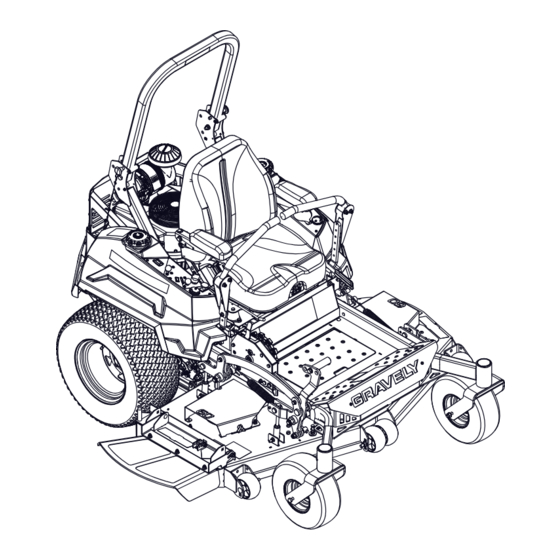
Pro-Turn
Manuel de I'utilisateur
E10
400
Operator's Manual
ENGLISH
FRANÇAIS
™
Models
992273 – Pro-Turn 452
(SN 060000 +)
992274 – Pro-Turn 460
(SN 060000 +)
992275 – Pro-Turn 460
(SN 060000 +)
992276 – Pro-Turn 472
(SN 060000 +)
992278 – Pro-Turn 460 EFI
(SN 060000 +)
992279 – Pro-Turn 472 EFI
(SN 060000 +)
992282 – Pro-Turn 452 EFI
(SN 060000 +)
992283 – Pro-Turn 460 EFI
(SN 060000 +)
992284 – Pro-Turn 472 EFI
(SN 060000 +)
992288 – Pro-Turn 460 EFI CARB
(SN 060000 +)
992289 – Pro-Turn 452 EFI CARB
(SN 060000 +)
992290 – Pro-Turn 472 EFI CARB
(SN 060000 +)
•
05092900B
1/17
Printed in USA
Advertisement
Table of Contents

Related Manuals for Gravely 992274


Summary of Contents for Gravely 992274
- Page 1 ™ Operator’s Manual Manuel de I’utilisateur Models 992273 – Pro-Turn 452 (SN 060000 +) 992274 – Pro-Turn 460 (SN 060000 +) 992275 – Pro-Turn 460 (SN 060000 +) 992276 – Pro-Turn 472 (SN 060000 +) 992278 – Pro-Turn 460 EFI (SN 060000 +) 992279 –...
-
Page 2: Table Of Contents
TABLE OF CONTENTS WELCOME ..... . 1 MAINTENANCE ....23 Service Position . -
Page 3: Welcome
WELCOME Congratulations on your purchase and welcome to the Gravely family! Every machine in the Gravely lineup is designed for long-lasting and unsurpassed performance. We are confident your machine will be part of your family for many years to come. -
Page 4: Safety
If you have purchased this 2. Warning product from a Gravely dealer, the dealer can provide you with training. WARNING: Indicates a Familiarize yourself and any other operators POTENTIALLY HAZARDOUS... -
Page 5: Safety Decals
4. Notice ALWAYS replace missing or damaged safety decals. Replacement decal information is in NOTICE: Indicates information or procedures the parts manual for your unit. Decals can be that are considered important but not hazard ordered from your dealer. related. If not followed, property damage See Figure 2 for safety decal locations. - Page 6 Safety Decal Descriptions 1.3 Tipping Hazard 1. DANGER! Avoid tipping hazard. DANGER! DO NOT operate on slopes over 15°. Read Operator’s Manual. 1.1 Amputation Hazard DO NOT operate on slopes over 15°. To avoid amputation hazard, DO NOT put hands near 1.4 Service Hazard rotating blades.
- Page 7 Amputation Hazard – Look behind when operating NEVER stick hands or feet the unit in reverse. under deck or shielded areas. 1.6 Loss of Traction Hazard Stop engine, remove key, and read manual before servicing or making If loss of traction is adjustments to unit.
-
Page 8: Safety Rules
6. ROTATING PARTS! 9. WARNING! Overfilling may cause severe damage to AVOID INJURY. Stay clear evaporative system. of rotating parts. NEVER fill fuel tank when engine is running, hot, or unit is indoors. Replace fuel cap securely 7. WARNING! and clean up spilled fuel. SERIOUS INJURY OR DEATH may result from Read Operator’s Manual. - Page 9 Understand: Use extreme care when approaching blind corners, shrubs, trees, or other objects that • How to operate all controls may block your view of a child. • The functions of all controls Keep children out of the mowing area and in •...
- Page 10 NEVER operate machine in a closed or Stop engine before removing grass catcher poorly ventilated area. or unclogging chute. ALWAYS maintain unit in safe operating Slow down before turning. condition. Damaged or worn out muffler can If you strike a foreign object, stop and cause fire or explosion.
- Page 11 Watch for holes, ruts, bumps, rocks, or other NEVER store the machine or fuel container hidden objects. Uneven terrain could where there is an open flame, spark, or pilot overturn the machine. Tall grass can hide light such as on a water or space heater or obstacles.
- Page 12 Follow the manufacturer’s recommendation Service for wheel weights or counterweights The use of non-genuine replacement parts Check grass catcher components and the or accessories could adversely affect discharge guard frequently and replace with machine operation and safety. the manufacturer’s recommended parts, Do not change engine governor setting or when necessary.
- Page 13 Transporting Unit Use extra care when loading or unloading the machine into a trailer. Secure unit chassis to transport vehicle. NEVER secure from rods or linkages that could be damaged. DO NOT transport machine while engine is running. ALWAYS turn off power to attachment and shut off fuel when transporting unit.
-
Page 14: Assembly
ASSEMBLY WARNING: Read and understand the Safety section before proceeding. 1. Remove wrap and packaging materials from unit. 2. Remove unit from shipping container. See Move Unit Manually on page 22. 3. Assemble seat. a. Remove hairpin from clevis pin and remove clevis pin from seat bracket. - Page 15 5. Rotate ROPS to operating position and 9. Check tire pressures and inflate to secure with lock pins. Secure lock pins recommendation. See Specifications on with hairpins. See Figure 7. page 46. WARNING: AVOID INJURY. Explosive separation of tire and rim parts is possible.
-
Page 16: Controls & Features
CONTROLS & FEATURES Models 992273, 992274, Models 992282, 992283, Models 992278, 992279 992275, 992276 992284, 992288, 992289, 992290 Figure 9 EN - 14... - Page 17 1. Ignition Key 17. Deck Lift Pedal 2. Choke Control Lever (Models 992273, 18. Height-of-Cut Adjustment Dial 992274, 992275, 992276) 19. Transport Lock Release Lever 3. Throttle Control Lever 20. Flip-up Discharge Chute 4. Power Take-off (PTO) Switch 21. Seat Adjustment Lever 5.
-
Page 18: Ignition Key
Controls power to mower blades. The engine will not start with the PTO switch in the on Figure 10 position. CHOKE CONTROL LEVER PTO / Blades On Models 992273, 992274, 992275, 992276 See Figure 11. Controls air intake to the engine. Choke PTO / Blades Off... -
Page 19: Oil Pressure Warning Light
OIL PRESSURE WARNING LIGHT TRANSPORT LOCK RELEASE LEVER See Figure 15. Illuminates when oil pressure is low. Stop See Figure 17. engine immediately and refer to engine Releases deck from transport lock position. manual. Transport lock will not engage with transport lock release lever in rear position. -
Page 20: Parking Brake Lever
STEERING LEVERS System by performing the tests below. Control the direction and speed of unit. The Contact your Gravely dealer for repair if levers gradually return to neutral when any of the tests fail. released and are locked in neutral when parking brake is engaged. -
Page 21: Position Rops
Lower Center Bar Test Steering PTO Parking Result See Figure 20. Levers Brake Starting Interlock WARNING: AVOID INJURY. Neutral Engaged Engine Lower the center bar only when starts. needed to drive under an object. Forward, Engaged Engine There is no rollover protection Neutral, does not with the center bar in the... -
Page 22: Adjust Seat
ADJUST SEAT WARNING: AVOID INJURY. Make all seat adjustments with the unit stopped, parking brake engaged and engine off. See Figure 21. Set Seat Height Toggle seat height adjustment switch left to raise seat or right to lower seat. Set Seat Position 1. -
Page 23: Open Fuel Valve
OPEN FUEL VALVE 5. Models 992273, 992274, 992275, 992276 only: If engine is cold, move See Figure 24. choke control lever to on position. DO • Turn fuel valve toward the left or right fuel NOT use choke on a warm engine. -
Page 24: Stop The Engine
MOVE UNIT MANUALLY Direction Lever Position of Travel See Figure 25. Left Turn Push right lever Bypass the transaxles to move the unit with farther forward the engine off. than the left lever. 1. Place unit in service position. See Service Position on page 23. -
Page 25: Release Transport Lock
Proper maintenance can prolong the life of unit. The Maintenance Schedule on Page 24 HOUR / MAINTENANCE METER shows the recommended service schedule. Your Gravely dealer can provide service and Timer-only Models adjustments to keep your unit operating at Timer measures engine runtime and cannot peak efficiency. -
Page 26: Maintenance Schedule
‡ Adjust clutch every 500 hours or once per season if used less than 500 hours. 1. Mode Button Figure 27 SERVICE PARTS See your Gravely dealer to purchase service MAINTENANCE SCHEDULE parts for your unit. Common Service Parts Description Qty. -
Page 27: Check Safety Interlock System
2. Check oil level in expansion tanks. Oil Models 992273, 992274, 992275, 992276 should reach the cold fill indicator mark. Description Qty. Part No. IMPORTANT: Engine should be cold when Air Filter (Outer) 21545400 checking initial oil level. Air Filter (Inner) -
Page 28: Check Tire Pressure
10. Reinstall filter cover. 11. Remove the vent / fill plug and add CHECK TIRE PRESSURE 15W-50 synthetic motor oil (Gravely Check and adjust tire pressure. See p/n 00057100) or equivalent until oil Specifications on page 46. -
Page 29: Check Mower Blades
CHECK MOWER BLADES Sharpen Blades Check blades for wear. Replace or sharpen as needed. CAUTION: DO NOT sharpen blades while attached to unit. CAUTION: AVOID INJURY. Use sturdy gloves or padding to protect hands when working with 1. Remove blades from unit. Discard blades mower blades. -
Page 30: Check Parking Brake
3. Check blade balance by sliding an CLEAN BATTERY unthreaded bolt through center hole. Hold the bolt level. If blade does not remain WARNING: AVOID INJURY. horizontal, sharpen the heavy end until Battery posts, terminals and blade is balanced. related accessories contain lead and lead compounds, chemicals Install Blades known to the State of California... -
Page 31: Charge Battery
5. Pump grease into fitting until grease squeezes through the seal in the wheel Jump Starting hub. Gravely does not recommend jump starting 6. Wipe away excess grease. your unit. Jump-starting can damage engine 7. Reinstall end caps onto wheel hub. -
Page 32: Check Carbon Canister Filters
CHECK CARBON CANISTER 3. Install new relay. FILTERS Models 992288, 992289, 992290 See Figure 36. Clean or replace carbon canister filters whenever engine air filter is cleaned or replaced. Figure 37 ADJUST TRANSAXLES 1. Carbon Canister Filter Check For Excessive Creep Figure 36 WARNING: AVOID INJURY. -
Page 33: Adjust Parking Brake Interlock
Adjust Neutral Position 6. Check wheel hubs for rotation. • If there is only slight rotation, stop If wheel hub has excessive rotation after engine, reinstall wheels, return unit to checking for excessive creep, adjust neutral operating position and advance to position. -
Page 34: Adjust Steering Levers
Set Parking Brake Neutral ADJUST STEERING LEVERS 1. Adjust transaxles. See Adjust Transaxles Align Steering Levers on page 30. If there is more than 3.2 mm (1/8") between 2. Stop engine, remove key and wait for the horizontal alignment of the steering moving parts to stop and for hot parts to levers, align the levers. -
Page 35: Adjust Unit To Drive Straight
Adjust Height ADJUST UNIT TO DRIVE STRAIGHT See Figure 42. The steering lever height may be adjusted for Adjust Tire Pressure operator comfort. 1. Place unit in service position. See 1. Place steering levers in neutral position Service Position on page 23. and engage parking brake. -
Page 36: Adjust Parking Brake
ADJUST PARKING BRAKE REPLACE MOWER BELTS See Figure 45. CAUTION: Damaged or worn IMPORTANT: Adjust both sides of parking belts may result in injury and / or brake equally. damage to the unit. Check belts 1. Check parking brake. See Check Parking for excessive wear or cracks Brake on page 28. - Page 37 8. Remove PTO belt. 1. Spring 2. Anchor Bolt 3. Mower Drive Belt Idler 4. Mower Drive Belt Figure 48 Models 992274, 992275, 992276, 992278, 992279, 992283, 992284, 992288, 992290 1. Spring 2. Anchor Bolt 3. PTO Belt Idler 4. PTO Belt...
- Page 38 Install Mower Drive Belt See Figure 50. 1. Install mower drive belt around bottom groove of split pulley at deck center and around bottom groove of right spindle pulley. 2. Reinstall idler spring hook around anchor bolt to apply tension to belt. 1.
-
Page 39: Replace Transaxle Drive Belt
REPLACE TRANSAXLE DRIVE 5. Remove clutch stop. See Figure 54. BELT Remove Transaxle Drive Belt 1. Place unit in service position. See Service Position on page 23. 2. Remove PTO belt from clutch. See Remove PTO Belt on page 34. CAUTION: Use care when releasing idler spring tension. -
Page 40: Adjust Anti-Scalp Wheels
Figure 57 1. Engine Sheave ADJUST DECK LIFT PEDAL 2. Transaxle Belt Idler See Figure 58. 3. Right Transaxle 1. Place steering levers in neutral position 4. Left Transaxle and engage parking brake. 5. Transaxle Belt 2. Stop engine, remove key and wait for Figure 56 moving parts to stop and for hot parts to cool. -
Page 41: Adjust Deck Lift Assist
ADJUST DECK LIFT ASSIST REMOVE / INSTALL MOWER DECK See Figure 59. The deck lift assist springs may be adjusted Remove Deck to modify deck lift assist and deck stability. 1. Place unit in service position. See Increased spring tension leads to easier deck Service Position on page 23. -
Page 42: Level And Pitch Mower Deck
See Figure 61. LEVEL AND PITCH MOWER 7. Remove hardware retaining deck lift links DECK to deck lift brackets. IMPORTANT: Make sure unit is on a flat, 8. Remove rear mounting pins securing level surface and that tires are inflated to the mounting arms to deck. - Page 43 Level Mower Deck Adjust Blade Pitch See Figure 64. IMPORTANT: Side-to-side deck heights MUST remain even after completing pitch 1. Lower the high side of deck: adjustment. a. Loosen jam nuts against deck- leveling links. NOTICE: Pitching the front of the blades lower than the rear provides a balance b.
-
Page 44: Adjust Clutch
ADJUST CLUTCH NOTICE: Adjust clutch every 500 hours or once per season if used less than 500 hours. See Figure 65. If clutch operates incorrectly or sounds abnormal, check the gap at the three inspection slots. Check Clutch 1. Place unit in service position. See Service Position on page 23. -
Page 45: Troubleshooting
Unit does not drive. page 37. Transaxles are faulty. Contact your Gravely dealer. Transaxle drive system is faulty. Contact your Gravely dealer. Hydraulic oil level is low. Add hydraulic oil. See Check Hydraulic System on page 25. EN - 43... - Page 46 Operator presence switch is not Activate switch by sitting on seat. engaged. Operator presence switch is Contact your Gravely dealer. faulty. PTO does not work. PTO belt is faulty. Replace PTO belt. See Replace Mower Belts on page 34. PTO switch, wiring, connectors Contact your Gravely dealer.
-
Page 47: Storage
SHORT-TERM STORAGE ACCESSORIES IMPORTANT: NEVER wash unit with high- pressure water or store outdoors. See your Gravely dealer for a complete list of 1. Allow unit to cool and clean with mild compatible accessories and attachments for soap and water. -
Page 48: Specifications
49 (13) Type Refer to engine manual. Transmission Type Hydrostatic Drive Use 15W-50 synthetic motor oil (Gravely p/n 00057100) or equivalent Hydraulic Oil Filter Drive Speed Forward Maximum – km/h (mph) 20.8 (13.0) Reverse Maximum – km/h (mph) 9.6 (6.0) - Page 49 49 (13) Type Refer to engine manual. Transmission Type Hydrostatic Drive Use 15W-50 synthetic motor oil (Gravely p/n 00057100) or equivalent Hydraulic Oil Filter Drive Speed Forward Maximum – km/h (mph) 20.8 (13.0) Reverse Maximum – km/h (mph) 9.6 (6.0)
- Page 50 49 (13) Type Refer to engine manual. Transmission Type Hydrostatic Drive Use 15W-50 synthetic motor oil (Gravely p/n 00057100) or equivalent Hydraulic Oil Filter Drive Speed Forward Maximum – km/h (mph) 20.8 (13.0) Reverse Maximum – km/h (mph) 9.6 (6.0)
- Page 51 49 (13) Type Refer to engine manual. Transmission Type Hydrostatic Drive Use 15W-50 synthetic motor oil (Gravely p/n 00057100) or equivalent Hydraulic Oil Filter Drive Speed Forward Maximum – km/h (mph) 20.8 (13.0) Reverse Maximum – km/h (mph) 9.6 (6.0)
-
Page 52: Warranty
Equipment Limited Warranty Warranty Ariens Company (Ariens) warrants to the original purchaser that Ariens, Gravely and Countax brand products purchased on or after 9/1/2016 and designated or labeled commercial products by Ariens Company will be free from defects in material and workmanship for the time period noted in the chart below. - Page 53 Exclusions – Items Not Covered by This Warranty • Parts that are not genuine Ariens, Gravely or Countax service parts are not covered by this warranty and may void the warranty. • Damages resulting from the installation or use of any part, accessory, or attachment which is not approved by the Ariens Company for use with product(s) identified herein are not covered by this warranty.
- Page 54 • Products are designed to the specifications in the area that the product was originally distributed. Different areas may have significantly different legal and design requirements. This warranty is limited to the requirements in the area in which the unit was originally distributed.
- Page 56 655 West Ryan Street Brillion, WI 54110 gravelymower.com gravely.custhelp.com...