Table of Contents

Related Manuals for Nelson N800iTM


Summary of Contents for Nelson N800iTM
- Page 1 Stud welding unit N800i As of: 24.08.2021 Manual part number: BE 1227 Stud welding unit N800iTM For Control Board Software 1.06 and higher Operation and Service Manual Tucker GmbH, Mail / Post: Max-Eyth-Str.1, 35394 Gießen, Germany...
-
Page 2: Table Of Contents
2.2 Safety notices .................... 16 2.3 Intended use ..................... 22 2.4 Guarantee and liability ................23 2.5 Use of original NELSON spare parts ............ 24 2.6 Copyright ....................24 3. Delivery and Transport ................25 3.1 Extent of delivery ..................25 3.2 Packing and dispatch ................ - Page 3 Stud welding unit N800i As of: 24.08.2021 Manual part number: BE 1227 5. Control and Display Elements .............. 40 5.1 Front Panel Controls and Displays ............40 6. Operation ....................43 6.1 Advice on Stud Welding................. 43 6.2 Basic Procedure ..................44 6.3 Weld Parameters ..................
- Page 4 Stud welding unit N800i As of: 24.08.2021 Manual part number: BE 1227 10.2 Problems / Possible Cause / Solution ..........108 10.3 Welding Problems ................109 10.4 Wiring Diagram Nelweld N800i............ 131 11.Annex ....................... 132 11.1 Disposal of the Nelweld N800i ............132 11.2 Disposal in accordance with the European directive ....
-
Page 5: Introduction
Trouble‐free operation of the Nelweld N800i welding unit can only be guaranteed with knowledge of the contents of these operating and ser‐ vice instructions. In case of difficulty or ambiguity please contact the customer service of Nelson, which will be very glad to help you. -
Page 6: Unit Description
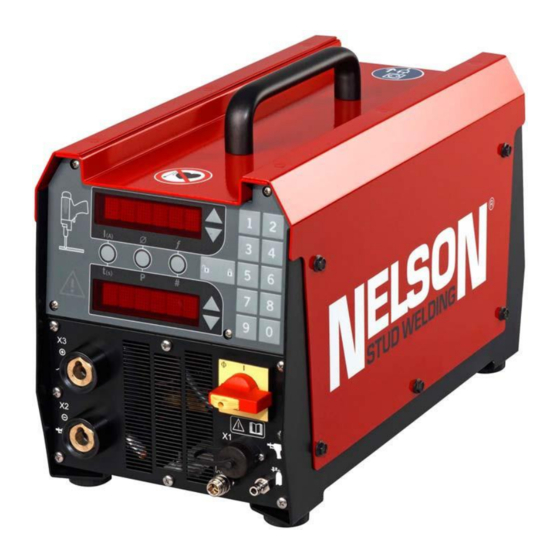
Stud welding unit N800i As of 24.08.2021 Manual part number: BE 1227 Unit Description The Nelweld N800i is a mobile welding unit, which in connection with a manual‐loading gun serves to weld metallic studs onto workpiece surfaces that are suited for welding. Commercially available studs can be welded both according to the drawn‐arc and the short‐cycle welding method with the Nelweld N800i. -
Page 7: Welding Method
Stud welding unit N800i As of 24.08.2021 Manual part number: BE 1227 See the pertinent gun operating instructions for knowledge on hand‐ ling weld guns in a professional and safe manner. The bright dot matrix display shows the function codes in plain text and can typically even be read in sunlight. -
Page 8: Operational Sequence
Stud welding unit N800i As of 24.08.2021 Manual part number: BE 1227 Operational Sequence When welding in keeping with the drawn‐arc method the gun must be loaded with a stud and a ceramic ferrule. When welding in keeping with the short‐cycle method the ceramic ferrule is usually not used. -
Page 9: Welding Elements
• An appropriate ceramic ferrule is required for every stud diameter • For differing ceramic ferrules corresponding ceramic ferrule holders are needed The LFH 000 catalogue offers an overview of the Nelson ceramic ferrule product range. Tucker GmbH, Mail / Post: Max-Eyth-Str.1, 35394 Gießen, Germany... -
Page 10: Material Combinations
Stud welding unit N800i As of 24.08.2021 Manual part number: BE 1227 Material Combinations The welding suitability of the different metals and the combinations of bolt material and base material depend on the welding process. The material combinations listed in the following table have been tried and tested and comply with ISO/TR 15608 Explanation of the superscript letters: a) For example for power transmission... - Page 11 Stud welding unit N800i As of 24.08.2021 Manual part number: BE 1227 1.4301 Suitable with Well 1.4303 restriction b Well Suitable with suitable for Not suitable 1.4401 restrictions b suitable for any for welding 1.4529 application a application a e 1.4541 1.4571 Suitable...
-
Page 12: Technical Data
As of 24.08.2021 Manual part number: BE 1227 Group 22: Not heatproof alloysNote! Note! Please consult a Nelson expert for material combinations that are not listed in the table and applications where aluminum studs should be welded. Technical Data Unit designation/Type:... - Page 13 Stud welding unit N800i As of 24.08.2021 Manual part number: BE 1227 Mains cable: H07RN‐F 4G 6 (4x6mm Length: Tucker GmbH, Mail / Post: Max-Eyth-Str.1, 35394 Gießen, Germany...
- Page 14 Stud welding unit N800i As of 24.08.2021 Manual part number: BE 1227 1.8.1 Dimensions Front Side Rear Tucker GmbH, Mail / Post: Max-Eyth-Str.1, 35394 Gießen, Germany...
- Page 15 Stud welding unit N800i As of 24.08.2021 Manual part number: BE 1227 1.8.2 Accessories (optional) Weld guns for manual stud loading: Weld gun: Type NS 40 SL complete with accessories: see NS 40 SL operating instructions Shielding gas device: order no. 67‐03‐04 Weld gun: Type NS 40 (B‐1, B‐2, B‐3, B‐4) complete with accessories:...
- Page 16 Composite Gun, NS 40, FL 67mm² 751‐585‐801 a Composite Gun, NS 20, FL 107mm² 512‐387‐056 Ethernet patch cable a. Contact Nelson Stud Welding sales representative for availability 1.8.4 Guns cable extension incl. control cable Length Cross section (mm2) Part Number / Socket inclusive control cable with BIN 4 67‐01‐16 / 50...
- Page 17 Stud welding unit N800i As of 24.08.2021 Manual part number: BE 1227 722‐000‐165a 722‐000‐167a 722‐000‐164a 722‐000‐166a 1.8.5 Mass cable extension Length (m) Cross section (mm Part Number / Socket 68‐03‐61 / 50 BKa 68‐04‐39 / 70 68‐03‐63 / 50 BK/SKb 652‐23‐41 / 50 67‐02‐09 / 70/95 ‐...
-
Page 19: Safety At Work
Stud welding unit N800i As of 24.08.2021 Manual part number: BE 1227 Safety at work 2.1 Safety Symbols Safety notices and warnings are made on the one hand for your personal safety and on the other hand for product safety. In these operating instructions they are made to stand out by means of the following safety symbol. -
Page 20: Safety Notices
Safety should be one of the utmost concerns for each user of a Nelweld unit. Knowledge of and careful attention to all safety advice granted in this manual is highly advised by Nelson Stud Welding, Inc. Observing all safety warnings and advice is a prerequisite for safe and correct handling and trouble‐free operation of the Nelweld series of stud welding power... - Page 21 Stud welding unit N800i As of 24.08.2021 Manual part number: BE 1227 Apprentices or personnel receiving on the job training may: • only work with the welding unit under supervision of an experienced person Personal protection equipment (PSA): Welding spatter, arcs and a noise level of 75dB. Consequently, the wearing of the following personal protection equipment is a mandatory stipulation: Symbol Beschreibung...
- Page 22 Stud welding unit N800i As of 24.08.2021 Manual part number: BE 1227 Symbol Meaning Only weld in rooms/areas, in which no additional hazards due to fire, explosion or moisture can occur. During welding strong electromagnetic fields come into being. These can: Symbol Meaning Interfere with or damage both electrical and electronical appliances...
- Page 23 Stud welding unit N800i As of 24.08.2021 Manual part number: BE 1227 Warning! In keeping with standard EN 60974-10 the welding unit N800i is suited for use in an industrial environment (limit class A). We expressly point out that units of limit class A can cause radio interference in residential and commercial areas! Safety measures prior to commencing work: Each time, prior to commencing work (shift change), check:...
- Page 24 Stud welding unit N800i As of 24.08.2021 Manual part number: BE 1227 • Secure the welding unit against unintentional restart-up Warning! • Opening the welding unit as well as a work inside the casing may only be carried out by authorized electrical specialists. •...
- Page 25 Stud welding unit N800i As of 24.08.2021 Manual part number: BE 1227 To protect against direct and indirect contact the welding unit is equip- ped with the following protective measures: Protection against penetration by foreign bodies (Ø Protection type IP 23 S: ≥12mm).
-
Page 26: Intended Use
Stud welding unit N800i As of 24.08.2021 Manual part number: BE 1227 2.3 Intended use During the design and manufacture of the Nelweld N800i the relevant guidelines and standards were observed. The welding head was built according to state of the art technology and is operationally reliable. -
Page 27: Guarantee And Liability
Stud welding unit N800i As of 24.08.2021 Manual part number: BE 1227 Warning! Contravention of intended use or usage exceeding this, is inadmissible and possibly dangerous. The manufacturer is not liable for damage resulting hereof; the opera- tor alone bears the risk! 1. -
Page 28: Use Of Original Nelson Spare Parts
2.5 Use of original NELSON spare parts With the use of original NELSON spare parts you are opting for quality. Only when original NELSON parts are used are we able to guaran‐ tee the safe and faultless operation of our products, provided they have been professionally installed or converted. -
Page 29: Delivery And Transport
3.4 Intermediate range If the Nelson N800i welding unit is not operated immediately after delivery, it must be put into intermediate storage in a secure place. The welding unit must be sufficiently protected against dust and moisture. -
Page 30: Operating Location
Stud welding unit N800i As of 24.08.2021 Manual part number: BE 1227 The mains cable may not be misused as a handle. 3.7 Operating Location The operating location of the N800i welding unit is restricted to areas of industrial and trading nature. Welding can cause radio interference in residential and commercial areas. - Page 31 Stud welding unit N800i As of 24.08.2021 Manual part number: BE 1227 Warning! In keeping with standard EN 60974-10 the welding unit N800i is sui- ted for use in an industrial environment (limit class A). We expressely point out that units of limit class A can cause radio interference in residential and commercial areas! Tucker GmbH, Mail / Post: Max-Eyth-Str.1, 35394 Gießen, Germany...
-
Page 32: Connection And Installation
Stud welding unit N800i As of 24.08.2021 Manual part number: BE 1227 Connection and Installation 4.1 Installation Precautions Attention must be paid to the fact that the welding unit is installed on horizontal, vibration‐free and non‐slip floor space The load‐carrying capacity of the floor space should be at least double the weight of the welding unit. - Page 33 Stud welding unit N800i As of 24.08.2021 Manual part number: BE 1227 Pos. Designation Description X3(+) Welding cable connection X2(-) Welding cable connection Gas connection Outpu Bottle Gas connection intput Control Cable connection Mains cable connection Warning! Prior to any connection work the Nelweld N800i welding unit must be switched off.
- Page 34 The Nelweld N800i may only be operated with a mains voltage of 400VAC/50/60Hz. The mains connection values are marked on the type plate. Nelson Stud Welding, Inc Part Nr. 7900 West Ridge Rd,Elyria,OH 44035 USA Serial Nr.
- Page 35 Stud welding unit N800i As of 24.08.2021 Manual part number: BE 1227 4.2.2 Connection of the Welding Cable Symbol Connection Connection of the welding cable of the gun is effected by means of the welding cable socket of the N800i which is marked with the gun symbol.
- Page 36 Stud welding unit N800i As of 24.08.2021 Manual part number: BE 1227 cable plug! 4.2.4 Connection of the Ground Cable Symbol Connection The welding current return takes place via the earth ground cable, which must be connected as follows to the earth ground cable socket of the Nelweld N800i.
- Page 37 Stud welding unit N800i As of 24.08.2021 Manual part number: BE 1227 Automatic mode (optional): • When a gun with manual stud loading is connected, the tubes from the gas source and the gun must be directly connected to the Nelweld 800i. Connection of the shielding gas source: Symbol Connection...
-
Page 38: Arc Blowing Effect
Stud welding unit N800i As of 24.08.2021 Manual part number: BE 1227 4.2.6 Connection of the workpiece As standard, the earth ground cable is equipped with two earth ground terminals which have to be connected to the workpiece. When connecting the earth terminals attention must be paid to the following: The earth ground terminals must be connected directly to the workpiece or to the workpiece fixture (welding bench, welding grid). - Page 39 Stud welding unit N800i As of 24.08.2021 Manual part number: BE 1227 Several remedial measures are available to reduce the consequences of the magnetic blowing effect-some of which are indicated below. Picture Remedial Measures In order to favorably influence the arc, the earth terminals must be placed as symmetrically as possible to the point of welding.
-
Page 40: Connection Diagram Short-Cycle And Drawn Arc Welding
Stud welding unit N800i As of 24.08.2021 Manual part number: BE 1227 4.4 Connection Diagram Short‐Cycle and Drawn Arc Welding Tucker GmbH, Mail / Post: Max-Eyth-Str.1, 35394 Gießen, Germany... -
Page 41: Connection Diagram Shielding Gas
Stud welding unit N800i As of 24.08.2021 Manual part number: BE 1227 4.5 Connection Diagram Shielding Gas Tucker GmbH, Mail / Post: Max-Eyth-Str.1, 35394 Gießen, Germany... -
Page 42: Additional Cautions
Stud welding unit N800i As of 24.08.2021 Manual part number: BE 1227 4.6 Additional Cautions SELECT SUITABLE LOCATION The N800i will operate in harsh environments. Even so, it is important that simple preventative measures are followed in order to assure long life and reliable operation. - Page 43 Stud welding unit N800i As of 24.08.2021 Manual part number: BE 1227 • When received directly from the factory, 230/460V machines are internally connected for 460VAC. 575V machines are internally connected for 575V from the factory. • Open the access panel on the rear of the machine. POWER CORD CONNECTION •...
-
Page 44: Control And Display Elements
Stud welding unit N800i As of 24.08.2021 Manual part number: BE 1227 Control and Display Elements 5.1 Front Panel Controls and Displays Tucker GmbH, Mail / Post: Max-Eyth-Str.1, 35394 Gießen, Germany... - Page 45 Stud welding unit N800i As of 24.08.2021 Manual part number: BE 1227 Pos. Designation Description Time/Current Mode Enables Time/Current weld parameter selection Setup selection by stud diameter and other Stud Expert Mode process parameter such as weld position Function Mode Configuration Change or Troubleshooting Add or subtract numeric values in time or Up/Down Arrow Keys...
- Page 46 Stud welding unit N800i As of 24.08.2021 Manual part number: BE 1227 Weld Tool Icon Tucker GmbH, Mail / Post: Max-Eyth-Str.1, 35394 Gießen, Germany...
-
Page 47: Operation
Stud welding unit N800i As of 24.08.2021 Manual part number: BE 1227 Operation 6.1 Advice on Stud Welding The advice on stud welding must be observed prior to commencing to weld. It contains information important to achieving good welds. 1. Welding elements and workpieces have to be suitable for wel‐ ding. Only use material combinations, which are specified in the operating and service instructions. -
Page 48: Basic Procedure
Stud welding unit N800i As of 24.08.2021 Manual part number: BE 1227 interference). Note! If welding on one workpiece with several welding units cannot be avoided, it is not recommended to weld simultaneously 6.2 Basic Procedure The process to begin welding using a Nelweld unit is very easy, once the proper electrical connections and gun connections are established: •... - Page 49 Stud welding unit N800i As of 24.08.2021 Manual part number: BE 1227 6.3.1 Setting Current and Reading the Current Display The current setting is the current setting during a weld, and can be viewed in the front panel’s upper display. It can be changed using Up/ Down arrow keys to the right of the current display in one (1) amp increments.
- Page 50 6. If the lift capability is marginal, i.e. it lifts a low lift height, but fails to lift at slightly higher lift height, consult your Nelson Rep. 6.3.4 Calibrate the gun drop time F31 It is recommended to calibrate the gun so that the welder understands the gun drop time and delivers the precise main arc time programmed.
- Page 51 Stud welding unit N800i As of 24.08.2021 Manual part number: BE 1227 and the actual drop time is saved in F31. 6.3.5 Weld Parameter Presets The power source has ten available preset configurations. Each of the- se is assigned a time and current setting for commonly welded stud sizes. To select a preset, simply press key 1, 2, 3, 4, 5, 6, 7, 8, 9, 0.
- Page 52 Stud welding unit N800i As of 24.08.2021 Manual part number: BE 1227 weld gun must be optimized. The results of the trial welds must be tested in keeping with DIN EN ISO 14555 Note! The weld parameters in the tables and in Stud Expert are provided as is, without warranty of any kind, either expressed or implied, including, but not limited to, the implied warranties of merchantability and fitness for a particular application.
- Page 53 6.3.7 Weld Parameters and Settings Note! Weld parameters and settings below are developed using Nelson equipment and Nelson studs. It is recommended to use fasteners from one manufacturer (Nelson studs) to ensure weld consistency and compatibility. In order to make sure the reproducibility of welds only studs from one batch may be used.
- Page 54 Stud welding unit N800i As of 24.08.2021 Manual part number: BE 1227 Factory Set Preset Weld Settings (Drawn Arc) Preset Nelson Stud Stud Size Current Time Bank 1 Type (Amps) (ms) IS‐Studs IS‐Studs IS‐Studs SD6, MR M8, S6 MP (F) M8...
- Page 55 Stud welding unit N800i As of 24.08.2021 Manual part number: BE 1227 6.3.8 Parameter for drawn‐arc procedure Stud Type Diameter Current Time Lift Plunge Lift Plunge Welds/m (msec) (mm) (mm) (mm) (mm) Stud Form tapered abutting face plane abutting face SD, MR, M8, SR MP(F) M10, S8 MR M10, S8...
- Page 56 Stud welding unit N800i As of 24.08.2021 Manual part number: BE 1227 6.3.9 Stud ExpertTM weld table The following Stud Expert weld table is programmed into the inverter controls. It allows for automatic weld settings based on stud type and diameter. Note! There are conditions that will filter the table for selection, or reveal only a subset of the table to the user...
- Page 57 Stud welding unit N800i As of 24.08.2021 Manual part number: BE 1227 l standard t standard l aluminium t aluminium Process 6mm Pitch Base 340, 170, 180, 280, Drawn Arc 6mm Full Base 370, 190, 200, 320, Drawn Arc 6mm SD6,MR 410, 250, 410,...
- Page 58 Stud welding unit N800i As of 24.08.2021 Manual part number: BE 1227 l standard t standard l aluminium t aluminium Process 7/16ʺ Full Base 720, 400, 380, 730, Drawn Arc 12mm Pitch Base 680, 380, 370, 690, Drawn Arc 12mm Full Base 780, 440, 420,...
- Page 59 Stud welding unit N800i As of 24.08.2021 Manual part number: BE 1227 6.3.10 Performing a Lift Check The gun lift can be measured by holding the gun trigger for a few seconds: • Isolate the gun (so as not to start weld). •...
-
Page 60: Rating Charts
Manual part number: BE 1227 6.4 Rating Charts 6.4.1 Maximum Weld Cable Length1 Maximum Weld Cable Length: Nelweld 800i Meter (feet) 1. Check with Nelson representative for a Weld Cable Length calculator Tucker GmbH, Mail / Post: Max-Eyth-Str.1, 35394 Gießen, Germany... -
Page 61: N800I Weld Cycle Timing
Stud welding unit N800i As of 24.08.2021 Manual part number: BE 1227 6.5 N800i Weld Cycle Timing This part explains how the inverter series controls main current and the weld gun. It further explains what elements affect drop time. For short cycle welding, the gun drop time and plunge time are critical components in the weld timing, so they must be configured, understood, and used correctly to get the optimum results. - Page 62 Stud welding unit N800i As of 24.08.2021 Manual part number: BE 1227 The Actual Weld Time is the time from the start of the main current to the time that the stud hits the workpiece. Under normal conditions, it will be equivalent to the Front Panel Time.
- Page 63 Stud welding unit N800i As of 24.08.2021 Manual part number: BE 1227 The important thing to note is that normally, the stud begins to drop at Front Panel Time – Drop Time. But if the Drop Time exceeds the Front Panel Time, the stud would need to begin to drop prior to the start of the weld in order to make the Actual Weld Time to be the same as the Front Panel Time.
-
Page 64: Drop Time Variables
Stud welding unit N800i As of 24.08.2021 Manual part number: BE 1227 6.6 Drop Time Variables This portion of the document describes several different conditions that affect drop time. This time duration will vary under many different conditions as outlined in the text below. -
Page 65: Inspection And Testing Of The Weld
Stud welding unit N800i As of 24.08.2021 Manual part number: BE 1227 6. Tighten foot‐retaining screws. These screws hold the foot in place during a weld while pressure is placed on the foot. Slippage of the foot will lead to a faster drop time. - Page 66 Stud welding unit N800i As of 24.08.2021 Manual part number: BE 1227 If the requirements are not met, a bending or tension test must be car‐ ried out on the three previous and on the three subsequent welds. The test results must be recorded in the production log. Attention! It must be noted that the welding work may only be continued when the test results are satisfactory!
- Page 67 Stud welding unit N800i As of 24.08.2021 Manual part number: BE 1227 “Short‐cycle‐method” ‐ Visual inspection 6.7.1 Inspection and testing of the weld is restricted in these operating and service instructions to the visual inspection of welds. A description of the mechanical and technological tests would go beyond the scope of these operating and service instructions.
- Page 68 Stud welding unit N800i As of 24.08.2021 Manual part number: BE 1227 “Drawn‐arc‐method“ ‐ Visual inspection 6.7.2 Inspection and testing of the weld is restricted in these operating and service instructions to the visual inspection of welds. A description of the mechanical and technological tests would go beyond the scope of these operating and service instructions.
-
Page 69: Weld Process Monitor
F32 is refreshed after each weld, and no weld histo ry is recorded. To save actual signals for all welds in production permanently as record keeping, contact Nelson for Nelware™ PC software. - Page 70 Stud welding unit N800i As of 24.08.2021 Manual part number: BE 1227 target is saved for the backlit preset. To clear a target stored in a preset, exit F mode by selecting I\t mode, then press both the Lock button and the desired preset button simultaneously. To clear a target that doesn’t have a preset association, exit any preset by manually changing the time\current, exit F mode by selecting I\t mode, then press both the Lock button and the Time‐down arrow simultaneously.
- Page 71 Stud welding unit N800i As of 24.08.2021 Manual part number: BE 1227 Use: The unit is now locked and ready to weld. When a weld is out of tolerance, the unit will flash the red triangle icon and display 'WELD ERROR - ENTER PASSWORD'. Enter the password to resume welding.
-
Page 72: Plunge Current
Stud welding unit N800i As of 24.08.2021 Manual part number: BE 1227 This is a medium level security mode, whereby the user must select a Lock Mode 4: password to lock the unit. Changes may be made to the weld settings by use of the presets and by adjusting the time / current by a predetermined range. -
Page 73: Pulse Welding (In Main Current)
Stud welding unit N800i As of 24.08.2021 Manual part number: BE 1227 The same weld made with standard method (plunge current is the same as the main arc current) is shown below for comparison: F46 = OFF (Disabled) By default plunge current is disabled. *Patent Pending 6.10 Pulse Welding (in main current) The welder normally welds with a constant DC current during main arc. -
Page 74: Pulse Cleaning (During The Beginning Of Main Arc Stage)
Stud welding unit N800i As of 24.08.2021 Manual part number: BE 1227 F49 = ON (Enabled) Due to low circuit inductance, it is possible to see current regulation errors when the pulse low current is too low, or the gap between high and low levels is too big. Use long and coiled cable around ferrous material can increase circuit inductance. -
Page 75: Password Reset
Stud welding unit N800i As of 24.08.2021 Manual part number: BE 1227 The example below shows 4 cleaning pulses of 1200A prior to the main arc current of 570A. It is recommended to use Nelware PC software to configure the pulse cleaning feature properly. -
Page 76: Constant Energy
Stud welding unit N800i As of 24.08.2021 Manual part number: BE 1227 set a target cable resistance. 6.15 Constant Energy* When F60 is enabled, the unit will attempt to deliver constant energy to the weld to compensate for lift height variation, flux load size and protrusion variation, zinc coating thickness variation, oil or oxide sur‐... -
Page 77: Chuck Change Indicator
Stud welding unit N800i As of 24.08.2021 Manual part number: BE 1227 6.16 Chuck Change Indicator A user programmable weld counter counts down and turns the chuck change indicator ON when it reaches zero. Refer to F29 code in Section 4 Operation Function Codes and Error Codes. 6.17 Configuring the stud feed interface to act as a ‘Weld Complete’... -
Page 78: F Code F61 - Pulse Cleaning Contaminant To Be Cleaned
Stud welding unit N800i As of 24.08.2021 Manual part number: BE 1227 when a good weld, no signal on failed weld according to the weld monitor. 6.18 F Code F61 ‐ Pulse Cleaning Contaminant to be Cleaned F61 has possible values of Zinc or Galvanized to Primer Paint, Oil or Oxide. The default value is set to Primer Paint. -
Page 79: Function Codes
As of 24.08.2021 Manual part number: BE 1221 Function Codes NOTE! Contact the factory or Nelson representative if F25 shows a different version for F code info not in the table below. The table below is for firmware version 1.05 only Description... - Page 80 Stud welding unit N800i As of 24.08.2021 Manual part number: BE 1221 code Description Possible Values Default Unit Notes Stud Expert Mode DOWNHAND, DOWN position VERTICAL, HAND OVERHEAD Stud Expert Mode MILD STEEL, MILD material STAINLESS, STEEL STEEL, ALUMI- Stud Expert Mode STUD STUD WELD process...
- Page 81 Stud welding unit N800i As of 24.08.2021 Manual part number: BE 1221 code Description Possible Values Default Unit Notes NORMAL Stud feed normal NORMAL This only applies when stud feed is enabled. CLOSED, NOR- le- vel OPEN MAL OPEN AFTER CON- AFTER When to get the signal.
- Page 82 Stud welding unit N800i As of 24.08.2021 Manual part number: BE 1221 code Description Possible Values Default Unit Notes Mode 1: Use the lock key to toggle blocking on all keys - no password protec- tion. Mode 2: Use the lock key to enter a password, lock key as ‘enter’. From there, all keys are blocked until you press lock again.
- Page 83 Stud welding unit N800i As of 24.08.2021 Manual part number: BE 1221 code Description Possible Values Default Unit Notes Lets user select which units are dis- played as stud sizes while in F24 Stud Expert Mode English, Metric oder English Stud Ex- pert mode.
- Page 84 Stud welding unit N800i As of 24.08.2021 Manual part number: BE 1221 code Description Possible Values Default Unit Notes This is a drop time measurement func- tion THAT DOES AN ACTUAL WELD. If F48 (Drop Time Configurati- on) is in either Manual or Auto mode, the measurement taken during the weld (while viewing this function) will be stored in this function and used in weld timing.
- Page 85 Stud welding unit N800i As of 24.08.2021 Manual part number: BE 1221 code Description Possible Values Default Unit Notes Turn this on to disable welding when a weld is out of specified weld energy/ drop range. Flashes ‘WELD ERROR!’ and requires a password F33 Disable Welding on OFF ON Weld Error...
- Page 86 Stud welding unit N800i As of 24.08.2021 Manual part number: BE 1221 code Description Possible Values Default Unit Notes Pulse Cleaning Time Time to remove from the main weld time per pulse done prior to the to Subtract for Each 0 to 500 weld.
- Page 87 Stud welding unit N800i As of 24.08.2021 Manual part number: BE 1221 code Description Possible Values Default Unit Notes F46 Plunge Current When enabled, the current will change to the selected value while the OFF ON Enable stud is plunging. When Plunge Current (F46) is enabled, this current will be used during F47 Plunge Current 50 to max.
- Page 88 Stud welding unit N800i As of 24.08.2021 Manual part number: BE 1221 code Description Possible Values Default Unit Notes F52 Pulse Weld Low 1000 This is the time the weld will deliver the low current (F50 current). Time Enable this to continue delivering weld current beyond the time settings F53 Cold Plunge Pre- if the stud does not short circuit before the weld current is scheduled to OFF ON...
- Page 89 Stud welding unit N800i As of 24.08.2021 Manual part number: BE 1227 code Description Possible Values Default Unit Notes F58 Keep Gun Lift En- Keeps the lifted after the weld for 5 se- conds for the purpose of OFF ON able troubleshoo- ting applications.
- Page 90 Stud welding unit N800i As of 24.08.2021 Manual part number: BE 1227 code Description Possible Values Default Unit Notes For automated systems, select the ap- propriate fieldbus selection to OFF, Van Rob, F64 Fieldbus Selection deter- mine the IO map and sequence of signals. For standard mode, Ford, GM disable this F code.
-
Page 91: Error Codes
Stud welding unit N800i As of 24.08.2021 Manual part number: BE 1227 7.1 Error Codes Fatal – meaning you have to power down Error Number Error Display What this really means to reset. Otherwise, Likely problem you weld again to reset. - Page 92 Stud welding unit N800i As of 24.08.2021 Manual part number: BE 1227 Fatal – meaning you have to power down Error Number Error Display What this really means to reset. Otherwise, Likely problem you weld again to reset. The control sensed that the REGULATION ERROR‐...
- Page 93 Stud welding unit N800i As of 24.08.2021 Manual part number: BE 1227 Fatal – meaning you have to power down Error Number Error Display What this really means to reset. Otherwise, Likely problem you weld again to reset. The thermal sensor was Thermal sensor on output PCB heatsink UNIT TOO HOT tripped.
- Page 94 Stud welding unit N800i As of 24.08.2021 Manual part number: BE 1227 Fatal – meaning you have to power down Error Number Error Display What this really means to reset. Otherwise, Likely problem you weld again to reset. If the unit is delivering 95% of the maximum power ca‐...
- Page 95 Stud welding unit N800i As of 24.08.2021 Manual part number: BE 1227 Fatal – meaning you have to power down Error Number Error Display What this really means to reset. Otherwise, Likely problem you weld again to reset. The configurations of the drop time(F31) and the front panel time make it such that the pilot arc supply must be...
- Page 96 Stud welding unit N800i As of 24.08.2021 Manual part number: BE 1227 7.1.1 Notes on which F codes change automatically 4‐Wire Gun Interfaces F2 ‐ Plunge F30 ‐ Short weld weld Action Result F31 ‐ Drop TIme Short Circuit F44 ‐ Preset Bank Other Notes Cycle Enable On‐Time...
-
Page 97: Weld Quality Problems
Stud welding unit N800i As of 24.08.2021 Manual part number: BE 1227 7.2 Weld Quality Problems Problem Possible Cause Solution Check the stud burn-off. If the burn-off is much greater than what is typical for that Time setting or diameter stud, the time and current settings may not be correct. Consult Section 2.6 current setting is too to ensure proper current and time settings are being used. - Page 98 Stud welding unit N800i As of 24.08.2021 Manual part number: BE 1227 Problem Possible Cause Solution Check the stud burn-off. If the burn-off is much less than what is typical for that Time setting or current diameter stud, the time and current settings may not be correct. Consult Section 2.6 setting is too low.
- Page 99 Stud welding unit N800i As of 24.08.2021 Manual part number: BE 1227 Problem Possible Cause Solution ® Plunge dampening is If the gun is a Heavy Duty gun, it is equipped with Tranquil Arc . Screw in the clear plastic too little.
- Page 100 Stud welding unit N800i As of 24.08.2021 Manual part number: BE 1227 Contamination of the base plate or stud may cause the arc to become erratic. Ensure that Base material the- re is no rust, scale, oil, water, residue, paint, galvanization, etc. present between the contamination.
-
Page 101: Maintenance
Stud welding unit N800i As of 24.08.2021 Manual part number: BE 1227 Maintenance 8.1 Care and cleaning The stud welding system requires no special care. See the operating instructions specific to the units for the necessary cleaning work to the gun and if need be to the feeder. The cleaning work specified below is necessary for the Nelweld N800i unit. -
Page 102: Routine Maintenance
Stud welding unit N800i As of 24.08.2021 Manual part number: BE 1227 8.2 Routine Maintenance Warning! Prior to commencing any maintenance work the welding unit must be switched off, disconnected from the mains and secured against restart! Only a qualified electrician should perform any work inside the unit’s casing. -
Page 103: Drawings And Parts Lists
Stud welding unit N800i As of 24.08.2021 Manual part number: BE 1227 Drawings and parts lists 9.1 Explosion drawing Final Assembly N800i Tucker GmbH, Mail / Post: Max-Eyth-Str.1, 35394 Gießen, Germany... - Page 104 Stud welding unit N800i As of 24.08.2021 Manual part number: BE 1227 9.1.1 Parts List Final Assembly N800i Item Part Number Comment Description 750‐611‐404 CHASSIS SUBASSEMBLY 750‐611‐401 VERTICAL PANEL SUBASSEMBLY 750‐611‐405 COVER SUBASSEMBLY 750‐611‐403 FRONT PANEL SUBASSEMBLY 750‐611‐205 BRACKET, CONTROL BOARD MOUNTING 750‐610‐074 CONTROL BOARD ASSEMBLY 750‐611‐081...
- Page 105 Stud welding unit N800i As of 24.08.2021 Manual part number: BE 1227 Item Part Number Comment Description LABEL, HIGH VOLTAGE, YELLOW 87‐07‐86 TRIANGLE 524‐005‐286 SCREW, M4x10 FHCS, SS 709‐256‐014 ROTARY SWITCH, POWER, 32A 716‐050‐002 FERRITE CORE, TOROID 24 in 103‐450‐156 TUBING HARNESS, CONTROL TO LEM 723‐245‐004...
-
Page 106: Cover Assembly
524‐001‐323 524‐001‐322 3/8‐24 x 3/4 HHCS, SS 724‐569‐004 DECAL, NELSON Comment: Sp = Spare part; Stp = Standard part; W = Wearing part; Ssp = Stud‐specific part; NS = Not shown Tucker GmbH, Mail / Post: Max-Eyth-Str.1, 35394 Gießen, Germany... -
Page 107: Chassis Sub Asm
Stud welding unit N800i As of 24.08.2021 Manual part number: BE 1227 9.3 Chassis Sub ASM Air Flow Direction Note! Rotate strain relief 30 degrees clockwise to have access to the screws Tucker GmbH, Mail / Post: Max-Eyth-Str.1, 35394 Gießen, Germany... - Page 108 Stud welding unit N800i As of 24.08.2021 Manual part number: BE 1227 9.3.1 Parts list chassis sub ASM Item Part Number Comment Description 750‐611‐221 CHASSIS WELDMENT 750‐611‐407 FAN SUB ASSEMBLY 729‐022‐008 Leveling feet 714‐074‐010 CABLE GLAND CABLE GLAND NUT 714‐074‐011 524‐005‐279 M4x16 PHMS, SS (FAN MOUNTING) 524‐005‐284...
-
Page 109: Front Panel Assembly
Stud welding unit N800i As of 24.08.2021 Manual part number: BE 1227 9.4 Front panel assembly Dinse Hardware See Note Note! Grease connectors by filling groove of rear cap with nyogel 760g (or equivalent), silicone free gre‐ ase before assembling Tucker GmbH, Mail / Post: Max-Eyth-Str.1, 35394 Gießen, Germany... - Page 110 Stud welding unit N800i As of 24.08.2021 Manual part number: BE 1227 9.4.1 Parts list Front panel assembly Item Part Number Comment Description 750‐611‐243 FRONT CONNECTOR PANEL 520‐001‐251 COUPLING,QUICK PLUG 520‐001‐252 COUPLING,QUICK SOCKET 520‐001‐320 FITTING,FEMALE,M6 TUBING x G1/8 85‐10‐02 DINSE,FEMALE (M10 SCREW) HRNS TRIGGER CONNECTOR (4 723‐245‐041 WIRE BINDER)
-
Page 111: Vertical Panel Assembly
Stud welding unit N800i As of 24.08.2021 Manual part number: BE 1227 9.5 Vertical panel assembly Primary Side Secondary Side Tucker GmbH, Mail / Post: Max-Eyth-Str.1, 35394 Gießen, Germany... - Page 112 Stud welding unit N800i As of 24.08.2021 Manual part number: BE 1227 9.5.1 Parts list Vertical panel assembly Item Part Number Comment Description 750‐611‐402 VERTICAL/TRANSFORMER ASSEMBLY 701‐175‐000 3 PHASE BRIDGE RECT. M5x35 HEX SPACER, FEMALE/FEMALE 729‐114‐201 (BRIDGE MOUNTING) 750‐611‐022 INPUT PCB ASSEMBLY 750‐611‐031 OUTPUT PCB ASSEMBLY 750‐610‐042...
-
Page 113: Troubleshooting
10.Troubleshooting 10.1 How to use Troubleshooting guide Warning! Service and Repair should only be performed by Nelson Factory Trained Personnel. Unauthorized repairs performed on this equipment my result in danger to the technician and machine operator and will invalidate your factory warranty. For your safety and to avoid Electrical Shock, please observe all safety notes and precautions detailed throughout this manual. - Page 114 Manual part number: BE 1227 Note! If you do not understand or are unable to perform the Recommended Course of Action safely, contact your local Nelson Authorized Field Service Facility. Replace Plexiglas after service! ☞ Note: Replace plexiglass after service!
-
Page 115: Problems / Possible Cause / Solution
Possible Cause Solution Major physical or • Contact your local authorized electrical damage is evident when the Nelson Field Service Facility for sheet metal covers are technical assistance removed. • Make certain that the fuses or breakers are properly sized. See... -
Page 116: Welding Problems
☞ If for any reason you do not understand the test procedures or are unable to person the tests/repairs safely, contact your Local Nelson Authorized Field Service Facility for technical troubleshooting assistance before you proceed! 10.3 Welding Problems... - Page 117 Manual part number: BE 1227 ☞ If for any reason you do not understand the test procedures or are unable to person the tests/repairs safely, contact your Local Nelson Authorized Field Service Facility for technical troubleshooting assistance before you proceed. Warning!
- Page 118 Stud welding unit N800i As of 24.08.2021 Manual part number: BE 1227 10.3.2 E002 Primary Voltage Dip too Low-Check Primary Voltage E002 Fatal, meaning you have to power down to continue welding Acknowledge, meaning the error will exist as long as the unit is powered on. (Note, welding can continue while the error exists) Description: The control board senses the +15VDC power supply provided to it.
- Page 119 Stud welding unit N800i As of 24.08.2021 Manual part number: BE 1227 Likely problems or items to check - in order from most likely to least likely: 1. Primary voltage is sagging during the weld enough for the 2. +15VDC auxillary supply to dip. 3.
- Page 120 Stud welding unit N800i As of 24.08.2021 Manual part number: BE 1227 10.3.3 E003 Capacitor Voltage Imbalance E003 Fatal, meaning you have to power down to continue welding Acknowledge, meaning the error will exist as long as the unit is powered on. (Note, welding can continue while the error exists) Description: When (and only when) running the unit on the high range 400, the primary capacitor...
- Page 121 Stud welding unit N800i As of 24.08.2021 Manual part number: BE 1227 10.3.4 E004 Regulation Error-Arc Went Out E004 Fatal, meaning you have to power down to continue welding Acknowledge, meaning the error will exist as long as the unit is powered on. (Note, welding can continue while the error exists) Description: If the control board senses that the current was more than 50% low while the...
- Page 122 Stud welding unit N800i As of 24.08.2021 Manual part number: BE 1227 10.3.5 E005 Regulation Error - Short circuit E005 Fatal, meaning you have to power down to continue welding Acknowledge, meaning the error will exist as long as the unit is powered on. (Note, welding can continue while the error exists) Description: If the control board senses that the current was 150% or higher of the setting while...
- Page 123 Stud welding unit N800i As of 24.08.2021 Manual part number: BE 1227 10.3.6 E006 Input Voltage Too High E006 Fatal, meaning you have to power down to continue welding Acknowledge, meaning the error will exist as long as the unit is powered on. (Note, welding can continue while the error exists) Description: When power is initially applied to the system, it goes through a series of relay...
- Page 124 Stud welding unit N800i As of 24.08.2021 Manual part number: BE 1227 which will involve some power down/up cycles. 3. Broken connection from control board to the switch board in V-F circuit. Check control board JP1 pins 1,9 for one pair, 2, 10 for the other. 4.
- Page 125 Stud welding unit N800i As of 24.08.2021 Manual part number: BE 1227 10.3.7 E007 Input Voltage Too Low E007 Fatal, meaning you have to power down to continue welding Acknowledge, meaning the error will exist as long as the unit is powered on. (Note, welding can continue while the error exists) Description When power is initially applied to the system, it goes through a series of relay...
- Page 126 Stud welding unit N800i As of 24.08.2021 Manual part number: BE 1227 the voltage readings correctly, which will involve some power down/up cycles. 3. Broken connection from control board to the switch board in V-F circuit. Check control board JP1 pins 1,9 for one pair, 2, 10 for the other. 4.
- Page 127 Stud welding unit N800i As of 24.08.2021 Manual part number: BE 1227 10.3.8 E008 Primary Overcurrent Error E008 Fatal, meaning you have to power down to continue welding Acknowledge, meaning the error will exist as long as the unit is powered on. (Note, welding can continue while the error exists) Description: When a dangerous primary current is sensed (by means of the Current transformer...
- Page 128 Stud welding unit N800i As of 24.08.2021 Manual part number: BE 1227 10.3.9 E009 Could Not Establish Pilot Arc E009 Fatal, meaning you have to power down to continue welding Acknowledge, meaning the error will exist as long as the unit is powered on. (Note, welding can continue while the error exists) Description: At the beginning of the weld, the pilot arc supply is turned on and the gun is...
- Page 129 Stud welding unit N800i As of 24.08.2021 Manual part number: BE 1227 10.3.10 E010 Capacitor Voltage Could Not Be Read E010 Fatal, meaning you have to power down to continue welding Acknowledge, meaning the error will exist as long as the unit is powered on. (Note, welding can continue while the error exists) Description: The voltage-to-frequency signal as provided by the switch boards...
- Page 130 Stud welding unit N800i As of 24.08.2021 Manual part number: BE 1227 10.3.11 E011 Unit Too Hot-Please Wait E011 Fatal, meaning you have to power down to continue welding Acknowledge, meaning the error will exist as long as the unit is powered on. (Note, welding can continue while the error exists) Description: When the internal temperature sensor trips, the control board disables welding so as...
- Page 131 Stud welding unit N800i As of 24.08.2021 Manual part number: BE 1227 10.3.12 E012 Short Circuit-Check Gun Lift Setting E012 Fatal, meaning you have to power down to continue welding Acknowledge, meaning the error will exist as long as the unit is powered on. (Note, welding can continue while the error exists) Description: If the stud voltage of the power unit is less than 20V while welding for over 100ms,...
- Page 132 Stud welding unit N800i As of 24.08.2021 Manual part number: BE 1227 10.3.13 E013 Weld Failed - Out of Tolerance E013 Fatal, meaning you have to power down to continue welding Acknowledge, meaning the error will exist as long as the unit is powered on. (Note, welding can continue while the error exists) Description: If the unit is configured to compare each weld results (Actual current, voltage, time,...
- Page 133 Stud welding unit N800i As of 24.08.2021 Manual part number: BE 1227 10.3.14 E014Warning-ColdPlunge-StudHitAfterCurrent Shut Off E014 Fatal, meaning you have to power down to continue welding Acknowledge, meaning the error will exist as long as the unit is powered on. (Note, welding can continue while the error exists) Description: The gun coil was de-energized and the stud did not hit the molten pool before current...
- Page 134 Stud welding unit N800i As of 24.08.2021 Manual part number: BE 1227 10.3.15 E015 Warning - Near Maximum Welding Output Capacity E015 Fatal, meaning you have to power down to continue welding Acknowledge, meaning the error will exist as long as the unit is powered on. (Note, welding can continue while the error exists) Description: The unit is at or above 95% of the power the unit is capable of delivering (voltage x...
- Page 135 Stud welding unit N800i As of 24.08.2021 Manual part number: BE 1227 10.3.16 E016 Warning - Check Weld Cables and Connectors - Press lock to clear E016 Connectors Fatal, meaning you have to power down to continue welding Acknowledge, meaning the error will exist as long as the unit is powered on. (Note, welding can continue while the error exists) Description: If a cable resistance target was saved using F55 and F56, upon each weld, the unit...
- Page 136 Stud welding unit N800i As of 24.08.2021 Manual part number: BE 1227 10.3.17 E017 Warning - Pilot Blew Out E017 Fatal, meaning you have to power down to continue welding Acknowledge, meaning the error will exist as long as the unit is powered on. (Note, welding can continue while the error exists) Description: During the pilot arc stage, the gun lifted as expected.
- Page 137 Stud welding unit N800i As of 24.08.2021 Manual part number: BE 1227 10.3.19 Additional Warning- WAIT is on upper display and CYCLE or CAP is on lower display Additional Warning - Wait is on upper display and CYCLE or CAP is on lower display Description ‘WAIT’...
-
Page 138: Wiring Diagram Nelweld N800I
Stud welding unit N800i As of 24.08.2021 Manual part number: BE 1227 10.4 Wiring Diagram Nelweld N800i Tucker GmbH, Mail / Post: Max-Eyth-Str.1, 35394 Gießen, Germany... -
Page 139: Annex
Stud welding unit N800i As of 24.08.2021 Manual part number: BE 1227 Annex 11.1 Disposal of the Nelweld N800i Disposal of the Nelweld N800i in an orderly and as pollution‐free as possible manner can be ensured by complying with the measures stat‐ ed below. You are thus making an important contribution towards environmental protection and waste management. -
Page 140: Disposal In Accordance With The European Directive
KrW-/AbfG: Law Regarding Waste Recycling and Man- agement (1994)! 11.2 Disposal in accordance with the European directive Only for EU countries Do not dispose of Nelson stud welding units and system components with household waste! Nelson stud welding units and system components are B2B devices and therefore exclusively designed for commercial use. -
Page 141: Abbreviations
Stud welding unit N800i As of 24.08.2021 Manual part number: BE 1227 11.3 Abbreviations The abbreviations used in this documentation in alphabetical order: AlMg Aluminum- Magnesium alloy AF type of cooling Fan (forced-air cooling) Ceramic ferrule Chromium German Standards Institute DIN EN European standard incorporated into German standards DIN ISO... -
Page 142: Literature
Stud welding unit N800i As of 24.08.2021 Manual part number: BE 1227 11.4 Literature ISO/TR 15608: Welding - Guidelines for a metallic material grouping system (2000) EN 60529: Degrees of protection provided by enclosures (IP-Code) (2000) EN 60974-1: Arc welding equipment Part 1 - Welding power sources (2005) EN 60974-12: Arc welding equipment...