Table of Contents
Advertisement
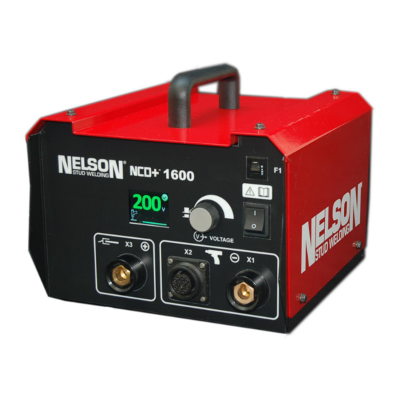
Operating the Capacitor Discharge
NCD+ 1000T/1600T Stud Welding Unit
Part No. 729-110-038 Rev. 1.21 | May 2016
Operations Manual
(729-110-038)
For Software Version 1.06 and later
These instructions are for experienced operators. If you are not fully familiar with
the principles of operation and safe practices for arc welding equipment, we urge you to
read AWS SP -"Safe Practices" available from the American Welding Society. Do not
permit untrained persons to install, operate or maintain this equipment. Do
not attempt to install or operate this equipment until you have read and fully
understand these instructions. If you do not fully understand these instructions,
contact your supplier for further information. Be sure to read the Safety section before
utilizing this equipment.
© 2014 Nelson Stud Welding, Inc. All Rights Reserved.
Advertisement
Table of Contents

Related Manuals for Nelson NCD+ 1000T


Summary of Contents for Nelson NCD+ 1000T
- Page 1 If you do not fully understand these instructions, contact your supplier for further information. Be sure to read the Safety section before utilizing this equipment. Part No. 729-110-038 Rev. 1.21 | May 2016 © 2014 Nelson Stud Welding, Inc. All Rights Reserved.
- Page 2 NCD+ 1000T & 1600T Limited Warranty NELSON’S only warranty is that goods being sold will be free from defects in workmanship and material. This warranty is expressly in lieu of other warranties, expressed or implied and whether statutory or otherwise, including any implied warranty of merchantability or fitness for a particular purpose.
- Page 3 Prevention in Use of Cutting and Welding Processes,” available from the National Fire Protection Association, Batterymarch Park, Quincy, MA 02269 Part No. 729-110-038 Rev. 1.21 | May 2016 © 2014 Nelson Stud Welding, Inc. All Rights Reserved.
- Page 4 Keep all safety devices and cabinet covers in position and in good repair. Use equipment only for its intended purpose. Do not modify it in any manner. Part No. 729-110-038 Rev. 1.21 | May 2016 © 2014 Nelson Stud Welding, Inc. All Rights Reserved.
-
Page 5: Table Of Contents
6.1 Wiring Diagram with Process Monitor .................33 Nelson NCD+ Welding Modes ..................34 7.1 Contact Mode Capacitor Discharge Welding ...............34 7.2 Auto-Gap Mode Capacitor Discharge Welding ............34 Contact Information ......................35 Part No. 729-110-038 Rev. 1.21 | May 2016 © 2014 Nelson Stud Welding, Inc. All Rights Reserved. -
Page 6: Connection And Installation
NCD+ 1000T & 1600T Manual | Connection and Installation 1 Connection and Installation Used to call attention to immediate hazards which, if not avoided, will result in immediate, serious personal injury or loss of life. Used to call attention to potential... -
Page 7: Connection
NCD+ 1000T & 1600T Manual | Connection and Installation 1.2 Connection With the exception of the input power cable, all of the connections are located on the front plate of the NCD+. Prior to any connection work, the NCD+ welding unit must be switched off. -
Page 8: Input Connection
NCD+ 1000T & 1600T Manual | Connection and Installation 1.2.1 Input Connection The NCD+ unit can only be operated with an input power voltage of 115 VAC / 60 Hz (Item 4 of Figure 1.1, Page 7). See the rating plate on the back panel of the unit. -
Page 9: Connection Of Gun Welding Cable
Figure 1.1, Page 7). It must be noted that the procedural safe operation of the system can only be guaranteed when either a Nelson Contact or a Nelson Auto Lift gun is connected. Gun Welding Cable Connection (X1) Align the locking pin of the welding cable plug to the locking groove of the welding cable socket. -
Page 10: Dual Connection Of Workpiece Ground Cable
NCD+ 1000T & 1600T Manual | Connection and Installation 1.2.4 Dual Connection of Workpiece Ground Cable The welding current return takes place via the Workpiece Ground Cable, which must be connected as follows to one of the Workpiece Ground Cable sockets (Item 3 of Figure 1.1, Page 7) on the front panel of the NCD+. -
Page 11: Specifications
NCD+ 1000T & 1600T Manual | Connection and Installation 1.3 Specifications CD WELDING UNIT MODEL NCD+™ 1000T NCD+™ 1600T 115 / 10 / 60 Input Voltage (V) / Current (A) / Frequency (Hz) 70 - 200 Capacitor Voltage (VDC) (Continuously Adjustable) -
Page 12: Mechanical Drawing
NCD+ 1000T & 1600T Manual | Connection and Installation 1.4 Mechanical Drawing Figure 1.6 NCD+ 1600T Dimensions Part No. 729-110-038 Rev. 1.21 | May 2016 © 2014 Nelson Stud Welding, Inc. All Rights Reserved. -
Page 13: Control And Display Elements
NCD+ 1000T & 1600T Manual | Control and Display Elements 2 Control and Display Elements 2.1 Front Panel Controls and Displays Weld Parameter Figure 2.1 Front Panel Controls Primary circuit breaker to protect the welding transformer from Circuit Breaker overloads (resettable). -
Page 14: Voltage Display Modes
NCD+ 1000T & 1600T Manual | Control and Display Elements 2.1.1 Voltage Display Modes Figure 2.2 Voltage Display (Enlarged View of Items 5 & 6 of Figure 2.1) RED when charging is in progress. GREEN when actual voltage matches with setpoint. -
Page 15: Stud Expert
NCD+ 1000T & 1600T Manual | Control and Display Elements 2.2 Stud Expert NOTE: Once the unit is powered up, press the knob once to enter the Process Monitor screen. NOTE: To access the Setup screen, return to the Voltage Selection screen (the home screen). -
Page 16: Process Monitor (Pm)
NCD+ 1000T & 1600T Manual | Control and Display Elements 2.3 Process Monitor (PM) NOTE: Once the unit is powered up, press the knob once to enter the Process Monitor screen. The Process Monitor uses a series of “teaching welds" as a target to check each production weld and to determine if the characteristics of a production weld fall within the natural scatter of teaching welds (“pass”). -
Page 17: Teaching Welds
NCD+ 1000T & 1600T Manual | Control and Display Elements 2.3.1 Teaching Welds NOTE: Once the unit is powered up, press the knob for 5 seconds to enter Process Monitor screen. NOTE: If you are unable to find the Process Monitor screen, make sure that WAVESCNENBL=ON in the Setup screen. -
Page 18: Setting Tolerances
NCD+ 1000T & 1600T Manual | Control and Display Elements 2.3 Teaching Welds (Cont’d) Scroll knob to go to the Weld Results screen which should read NO TARGET (Item 1 of Figure 2.6) as the last weld wasn’t monitored. The subsequent welds will be monitored by the new target, and the first line should indicate pass or fail (Item 2). -
Page 19: Operating Process Monitor
NCD+ 1000T & 1600T Manual | Control and Display Elements Adjust or disable individual parameters (ArcT, ENERGY, TIP, etc) to override tolerances automatically set by teaching and MAIN TOL MULT (Figure 2.8). Scroll down through the Setup screen for more individual tolerances. -
Page 20: Normal Operation
NCD+ 1000T & 1600T Manual | Normal Operation 3 Normal Operation NOTE: Refer to Figure 2.1 (Page 13) for item references throughout the following instructions. 3.1 Powering Up Before power up, ensure that all cables are properly connected. Press the On/Off Power switch (Item 2) to the right of the knob to start the unit. -
Page 21: Error Codes
NCD+ 1000T & 1600T Manual | Normal Operation 3.3 Error Codes Only qualified personnel should perform maintenance. Some functional errors are highlighted by appearance of an error code with the display EXX. Error Malfunction Solution Number Stop using the Power Source until issue is resolved. -
Page 22: Weld Quality Visual Inspection
NCD+ 1000T & 1600T Manual | Normal Operation 3.4 Weld Quality Visual Inspection Issue: Too cold Issue: Acceptable Weld Issue: Too Hot Weld Flash: Not Visible Weld Flash: Normal, No Weld Flash: Excessive flash Weld: Very weak, Will break significant weld splatter... -
Page 23: Welding Parameters
NCD+ 1000T & 1600T Manual | Welding Parameters 4 Welding Parameters 4.1 Contact Gun NCD+™ 1000 NCD+™ 1600 Plunge Depth Pressure Stud Size Material Voltage Voltage lbs N Carbon Steel 0.12 53 100 120 #6 (M3) Stainless Steel 0.12 53 100 100 Carbon Steel 0.12... -
Page 24: Weld Setting Recommendations
NCD+ 1000T & 1600T Manual | Welding Parameters 4.3 Weld Setting Recommendations Weld Setting Change Effect on Welds Capacitance Increase Hotter Voltage Increase Hotter Spring Pressure Increase Colder Contact Mode-Plunge Increase Colder Gap Mode-Gap Increase Colder Stud Tip Length Increase Hotter Part No. -
Page 25: Parts List & Exploded View
NCD+ 1000T & 1600T Manual | Parts List & Exploded View 5 Parts List & Exploded View 5.1 NCD+ 1000T (750-614-511) *SPARE PARTS ARE INDICATED BY THE QUANTITIES LISTED IN THE SPARE COLUMN OF THE TABLE. PART NO. DESCRIPTION TORQUE... - Page 26 NCD+ 1000T & 1600T Manual | Parts List & Exploded View 524-005-315 SCREW, HHCS FLANGED, M5 x 10 SS 524-005-078 NUT, HEX, M10 SS 524-005-291 WASHER, FLAT, M5 SS 524-005-304 WASHER, LOCK, M5 SS 524-005-316 SCREW, HHCS, M5 x 30 SS...
- Page 27 NCD+ 1000T & 1600T Manual | Parts List & Exploded View Part No. 729-110-038 Rev. 1.21 | May 2016 © 2014 Nelson Stud Welding, Inc. All Rights Reserved.
- Page 28 NCD+ 1000T & 1600T Manual | Parts List & Exploded View Part No. 729-110-038 Rev. 1.21 | May 2016 © 2014 Nelson Stud Welding, Inc. All Rights Reserved.
-
Page 29: Ncd+ 1600T (750-614-521)
NCD+ 1000T & 1600T Manual | Parts List & Exploded View 5.2 NCD+ 1600T (750-614-521) *SPARE PARTS ARE INDICATED BY THE QUANTITIES LISTED IN THE SPARE COLUMN OF THE TABLE. PART NO. DESCRIPTION TORQUE *SPARE 750-614-233 CHASSIS 750-614-234 COVER 750-614-235 BRACKET, MTG., PWR PCB... - Page 30 NCD+ 1000T & 1600T Manual | Parts List & Exploded View 524-005-304 WASHER, LOCK, M5 SS 524-005-312 SCREW, HHCS, M5 x 35 SS 524-005-302 WASHER, FLAT, M3 SS 1.7' 727-029-218 EDGE TRIM, PLASTIC W/METAL CORE 524-005-336 SCREW, PHMS, M4 x 50 SS...
- Page 31 NCD+ 1000T & 1600T Manual | Parts List & Exploded View Part No. 729-110-038 Rev. 1.21 | May 2016 © 2014 Nelson Stud Welding, Inc. All Rights Reserved.
-
Page 32: Wiring Diagram
NCD+ 1000T & 1600T Manual | Wiring Diagram 6 Wiring Diagram Part No. 729-110-038 Rev. 1.21 | May 2016 © 2014 Nelson Stud Welding, Inc. All Rights Reserved. -
Page 33: Wiring Diagram With Process Monitor
NCD+ 1000T & 1600T Manual | Wiring Diagram Wiring Diagram with Process Monitor Part No. 729-110-038 Rev. 1.21 | May 2016 © 2014 Nelson Stud Welding, Inc. All Rights Reserved. -
Page 34: Nelson Ncd+ Welding Modes
Gap. Each method has its own uses and set-up requirements. The method you select will be determined by the metals to be joined, the esthetics strength and fixturing. Nelson Stud Welding will assist you in determining which method best suits your needs. -
Page 35: Contact Information
NCD+ 1000T & 1600T Manual | Contact Information 8 Contact Information North America Sales Offices and Warehouses *Chicago *Philadelphia **Elyria *Westlake 18601 Graphic Court 260 Boot Road 7900 West Ridge Road 835 Sharon Drive Tinley Park, IL 60477 Downingtown, PA 19335 P.O.