Table of Contents
Advertisement
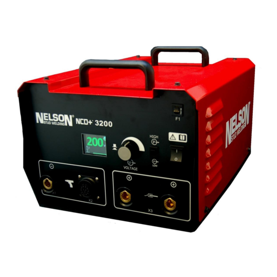
Operating the Capacitor Discharge
NCD+ 3200 Stud Welding Unit
Part No. 729-110-037 Rev. 1.31 | May 2016
Operations Manual
(729-110-037)
For Software Version 1.06 and later
These instructions are for experienced operators. If you are not fully familiar with
the principles of operation and safe practices for arc welding equipment, we urge you to
read AWS SP -"Safe Practices" available from the American Welding Society. Do not
permit untrained persons to install, operate or maintain this equipment. Do
not attempt to install or operate this equipment until you have read and fully
understand these instructions. If you do not fully understand these instructions,
contact your supplier for further information. Be sure to read the Safety section before
utilizing this equipment. .
© 2014 Nelson Stud Welding, Inc. All Rights Reserved.
Advertisement
Table of Contents

Related Manuals for Nelson NCD+ 3200


Summary of Contents for Nelson NCD+ 3200
- Page 1 If you do not fully understand these instructions, contact your supplier for further information. Be sure to read the Safety section before utilizing this equipment. . Part No. 729-110-037 Rev. 1.31 | May 2016 © 2014 Nelson Stud Welding, Inc. All Rights Reserved.
- Page 2 NCD+ 3200 Limited Warranty NELSON’S only warranty is that goods being sold will be free from defects in workmanship and material. This warranty is expressly in lieu of other warranties, expressed or implied and whether statutory or otherwise, including any implied warranty of merchantability or fitness for a particular purpose.
- Page 3 Prevention in Use of Cutting and Welding Processes,” available from the National Fire Protection Association, Batterymarch Park, Quincy, MA 02269 Part No. 729-110-037 Rev. 1.31 | May 2016 © 2014 Nelson Stud Welding, Inc. All Rights Reserved.
- Page 4 Keep all safety devices and cabinet covers in position and in good repair. Use equipment only for its intended purpose. Do not modify it in any manner. Part No. 729-110-037 Rev. 1.31 | May 2016 © 2014 Nelson Stud Welding, Inc. All Rights Reserved.
-
Page 5: Table Of Contents
Welding Parameters......................23 4.1 Contact Gun........................ 23 4.2 Auto-Gap Gun ......................23 4.3 Weld Setting Recommendations ................. 24 NCD+ 3200 Parts List & Exploded View .................25 Wiring Diagrams for NCD+ ....................29 6.1 Standard System ......................29 6.2 Autofeed System ......................30 Nelson NCD+ Welding Modes ..................31... -
Page 6: Connection And Installation
NCD+ circuit boards, particularly when sharing the same work piece. For more information please consult your local Nelson service support. Part No. 729-110-037 Rev. 1.31 | May 2016 © 2014 Nelson Stud Welding, Inc. All Rights Reserved. -
Page 7: Connection
1 Gun Welding Cable Connection (-) x1 3 Workpiece Ground Cable Dual Connection (+) x3 2 Gun Control Cable Connection x2 4 Input Power Cable Connection Part No. 729-110-037 Rev. 1.31 | May 2016 © 2014 Nelson Stud Welding, Inc. All Rights Reserved. -
Page 8: Input Connection
It could result in unsafe conditions. Fusing with slow response characteristics. Part No. 729-110-037 Rev. 1.31 | May 2016 © 2014 Nelson Stud Welding, Inc. All Rights Reserved. -
Page 9: Connection Of Gun Welding Cable
Figure 1.1, Page 7). It must be noted that the procedural safe operation of the system can only be guaranteed when either a Nelson Contact or a Nelson Auto Lift gun is connected. Gun Welding Cable Connection (X1) Align the locking pin of the welding cable plug to the locking groove of the welding cable socket. -
Page 10: Dual Connection Of Workpiece Ground Cable
(pipelines, shipbuilding, etc.). Place the workpiece ground terminals, if possible, at the same distance from the point of welding when two ground clamps are used. Part No. 729-110-037 Rev. 1.31 | May 2016 © 2014 Nelson Stud Welding, Inc. All Rights Reserved. -
Page 11: Specifications
Dual Ground Compatible Guns NCD+ Contact, NCD+ Auto-Gap Yes – Optional Process Monitor Contact Safety Check Chuck Saver Stud Expert Display Graphic Color Display Part No. 729-110-037 Rev. 1.31 | May 2016 © 2014 Nelson Stud Welding, Inc. All Rights Reserved. -
Page 12: Mechanical Drawing
NCD+ 3200 Manual | Connection and Installation 1.3.1 Mechanical Drawing Figure 1.5 Front & Side Views of NCD+ 3200 with Dimensions Part No. 729-110-037 Rev. 1.31 | May 2016 © 2014 Nelson Stud Welding, Inc. All Rights Reserved. -
Page 13: Control And Display Elements
NCD+ 3200 Manual | Control and Display Elements 2 Control and Display Elements 2.1 Front Panel Controls and Displays Weld Parameter Figure 2.1 Front Panel Controls Circuit Breaker Primary circuit breaker to protect the welding transformer from overloads (resettable). The main switch controls the input power to the machine. Upon powering up, the internal... -
Page 14: Voltage Display Modes
NCD+ 3200 Manual | Control and Display Elements 2.1.1 Voltage Display Modes RED when charging is in progress. GREEN when actual voltage matches with setpoint. Voltage Cap Charge Status Setpoint Ready (GREEN) Charging (WHITE) Not Ready (RED) Discharging (WHITE) Workpiece... -
Page 15: Stud Expert
NCD+ 3200 Manual | Control and Display Elements 2.2 Stud Expert NOTE: Once the unit is powered up, press the knob once to enter the Process Monitor screen. NOTE: To access the Setup screen, return to the Voltage Selection screen (the home screen). -
Page 16: Process Monitor (Pm)
NCD+ 3200 Manual | Control and Display Elements 2.3 Process Monitor (PM) NOTE: Once the unit is powered up, press the knob once to enter the Process Monitor screen. The Process Monitor uses a series of “teaching welds" as a target to check each production weld and to determine if the characteristics of a production weld fall within the natural scatter of teaching welds (“pass”). -
Page 17: Teaching Welds
NCD+ 3200 Manual | Control and Display Elements 2.3.1 Teaching Welds NOTE: Once the unit is powered up, press the knob once to enter the Process Monitor screen. NOTE: If you are unable to find the Process Monitor screen, make sure that WAVESCNENBL=ON in the Setup screen. -
Page 18: Setting Tolerances
NCD+ 3200 Manual | Control and Display Elements 2.3 Teaching Welds (Cont’d) Scroll knob to go to the Weld Results screen which should read NO TARGET (Item 1 of Figure 2.6) as the last weld wasn’t monitored. The subsequent welds will be monitored by the new target, and the first line should indicate pass or fail (Item 2). -
Page 19: Operating Process Monitor
NCD+ 3200 Manual | Control and Display Elements Adjust or disable individual parameters (ArcT, ENERGY, TIP, etc) to override tolerances automatically set by teaching and MAIN TOL MULT (Figure 2.8). Scroll down through the Setup screen for more individual tolerances. -
Page 20: Normal Operation
The unit will not recharge even if the trigger is pulled again before the chuck is removed from the welded stud known as the Chuck Saver™. Part No. 729-110-037 Rev. 1.31 | May 2016 © 2014 Nelson Stud Welding, Inc. All Rights Reserved. -
Page 21: Error Codes
At 45°C or lower ambient Replace control board. temperature TEMP Trip with thermal switch Let it cool down. Check for loose cable connections. mounted on heat-sink Part No. 729-110-037 Rev. 1.31 | May 2016 © 2014 Nelson Stud Welding, Inc. All Rights Reserved. -
Page 22: Weld Quality Visual Inspection
Weld: Good, strong Weld: Weak, May break reduce spring pressure, or Adjustments: None required Adjustments: Reduce voltage, increase capacitance increase spring pressure, or reduce capacitance Part No. 729-110-037 Rev. 1.31 | May 2016 © 2014 Nelson Stud Welding, Inc. All Rights Reserved. -
Page 23: Welding Parameters
0.14 1/4" (M6) Carbon Steel 0.12 [6.4 mm] Stainless Steel 0.12 Aluminum 0.12 5/16" (M8) Carbon Steel 0.08 [7.9 mm] Stainless Steel 0.08 Part No. 729-110-037 Rev. 1.31 | May 2016 © 2014 Nelson Stud Welding, Inc. All Rights Reserved. -
Page 24: Weld Setting Recommendations
Capacitance Increase Hotter Voltage Increase Hotter Spring Pressure Increase Colder Contact Mode-Plunge Increase Colder Gap Mode-Gap Increase Colder Stud Tip Length Increase Hotter Part No. 729-110-037 Rev. 1.31 | May 2016 © 2014 Nelson Stud Welding, Inc. All Rights Reserved. -
Page 25: Ncd+ 3200 Parts List & Exploded View
NCD+ 3200 Manual | NCD+ 3200 Parts List & Exploded View 5 NCD+ 3200 Parts List & Exploded View *SPARE PARTS ARE INDICATED BY QUANTITIES IN SPARE COLUMN IN TABLE PART NO. DESCRIPTION TORQUE *SPARE 750-614-220 Chassis, NCD+ 3200 729-114-102... - Page 26 NCD+ 3200 Manual | NCD+ 3200 Parts List & Exploded View 524-005-339 Nut, Hex, M6, SS 20 in/lbs 524-005-273 Nut, KEPS, M6, SS 20 in/lbs 524-005-279 Screw, M4 x 16, PHMS, SS 10 in/lbs 750-614-229 NCD+ 3200 Shunt Connector 524-005-311 Washer, Belleville, M6, SS Washer, Flat, 1/4″, SS...
- Page 27 NCD+ 3200 Manual | NCD+ 3200 Parts List & Exploded View 723-247-104 Power Board to Caps, Fan & Bridge Harness 723-247-105 (-) DC Bridge to (-) Cap Buss Harness 723-247-107 Voltage Sense Resistor Harness 723-247-012 Power Switch to Circuit Breaker Wire...
- Page 28 NCD+ 3200 Manual | NCD+ 3200 Parts List & Exploded View Part No. 729-110-037 Rev. 1.31 | May 2016 © 2014 Nelson Stud Welding, Inc. All Rights Reserved.
-
Page 29: Wiring Diagrams For Ncd
NCD+ 3200 Manual | Wiring Diagrams for NCD+ 6 Wiring Diagrams for NCD+ 6.1 Standard System Part No. 729-110-037 Rev. 1.31 | May 2016 © 2014 Nelson Stud Welding, Inc. All Rights Reserved. -
Page 30: Autofeed System
NCD+ 3200 Manual | Wiring Diagrams for NCD+ 6.2 Autofeed System Part No. 729-110-037 Rev. 1.31 | May 2016 © 2014 Nelson Stud Welding, Inc. All Rights Reserved. -
Page 31: Nelson Ncd+ Welding Modes
Gap. Each method has its own uses and set-up requirements. The method you select will be determined by the metals to be joined, the esthetics strength and fixturing. Nelson Stud Welding will assist you in determining which method best suits your needs. -
Page 32: Contact Information
Elyria, OH 44036-2019 USA Via Miraflores, 20 Phone: 440.329.0400 Nichelino, (TO) I-10042 Fax: 440.329.0597 Italy World Wide Web: NelsonStudWelding.com Phone:39.011.6059238 Fax: 39.011.6059230 E-mail: Nelson.Sales@NelsonStud.com Part No. 729-110-037 Rev. 1.31 | May 2016 © 2014 Nelson Stud Welding, Inc. All Rights Reserved.