
Related Manuals for Nelson INTRA 2100


Summary of Contents for Nelson INTRA 2100
- Page 1 Operating manual Stud welding unit INTRA 2100/1400 for drawn arc and short-term drawn arc processes Edition: 2021-07 Revision: Rev. A / 07.2021 / EN Document number...
- Page 2 INTRA 2100/1400 Operating manual Model / Device: Stud welding unit Original- Manufacturer TUCKER GmbH A Division of STANLEY Engineered Fastening Max-Eyth-Straße 1 D-35394 Gießen, Germany Tel.: +49 641 405 0 Fax: +49 641 405-383 E-mail: sef.europe@sbdinc.com Internet: www.tucker.eu www.stanleyengineeredfastening.com/brands/tucker Imprint...
-
Page 3: Table Of Contents
Combinations for the drawn arc process ............9 1.4.2 Combinations for the short cycle process ............ 9 Technical data ................10 1.5.1 INTRA 2100 technical data ................ 10 1.5.2 INTRA 1400 technical data ................ 11 Accessories (optional): .............. 12 Declaration of Conformity ............13 Work safety ................... - Page 4 Visual inspection “short cycle drawn arc process” ........47 6.5.3 Mechanical inspection (general) ..............48 Maintenance ..................49 Care and cleaning ............... 49 Maintenance intervals..............50 Stud welding units Operating manual Date: July 2021 INTRA 2100/1400 07.2021 / EN Rev.:...
- Page 5 8.2.4 Fault: Welding ..................56 8.2.5 Electronics error search ................57 Appendix....................59 Disposal of the welding device ..........59 Abbreviations ................61 Bibliography ................62 Stud welding units Operating manual Date: July 2021 INTRA 2100/1400 07.2021 / EN Rev.:...
-
Page 6: Introduction
Page 1 Introduction General remarks This operating manual is about the INTRA 2100/1400 welding device and is intended for operating and service personnel. The INTRA 2100/1400 welding device can only be operated safely and reliably with knowledge of the contents of this operating manual. Before starting up your device, we ask that you thoroughly read this operating manual. -
Page 7: Device Description
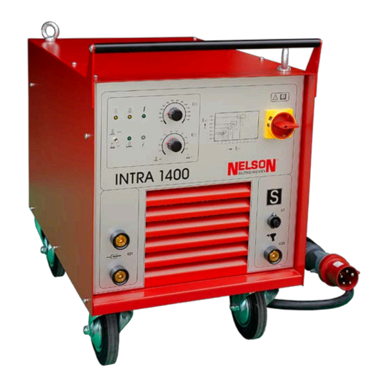
Introduction Page 2 Device description The INTRA 2100/1400 is a robust, high-performance welding control device and together with the NS 40 B or NS 40 SL welding gun forms a reliable stud welding system. When properly used, this device will always provide good, reliable work results. - Page 8 (see DGUV Information 209-010). Standard equipment • 1 INTRA 2100/1400 control device with crane lugs and fixed casters (casters with parking brakes). • 1 NS 40 B or NS 40 SL welding gun with 5 m or 3 m connecting cable, with customer’s choice of stud holder (NS 40 B welding gun complete with foot plate...
-
Page 9: Description Of Stud Welding Process
This weld process generally welds peg-shaped connection elements full surface to the workpiece. The INTRA 2100/1400 welding device can be used to weld ordinary commercial studs both in the drawn arc process (abbreviated BH 100 according to DVS 0902) and the short cycle drawn arc process (abbreviated BH 10 according to DVS 0902): 1. - Page 10 Moreover, it protects the welder from the arc and hot weld splatter. Ceramic ring Stud welding units Operating manual Date: July 2021 INTRA 2100/1400 07.2021 / EN Rev.:...
-
Page 11: Short Cycle Weld Process
Drawn arc process with shielding gas (BH 100 SG per DVS 0902) For special cases, the INTRA 2100/1400 welding device can be retrofitted with a gas module for stud welding under shielding gas. Here changes to the performance data and parameter inputs must be taken into account. - Page 12 In comparison to the drawn arc process, the same weld diameters are welded weld time decreased by a factor of 10, but considerably increased current. Therefore, no additives to deoxidize the weld point are needed. Stud welding units Operating manual Date: July 2021 INTRA 2100/1400 07.2021 / EN Rev.:...
-
Page 13: Material Combinations
Material combinations that are not listed in the table can be tested in the welding laboratory. Contact your Tucker GmbH technical consultant. EN ISO 15614-1, 2: Specification and qualification of welding procedures for metallic materials – Welding procedure test Stud welding units Operating manual Date: July 2021 INTRA 2100/1400 07.2021 / EN Rev.:... -
Page 14: Combinations For The Drawn Arc Process
(see the table on the previous page). The special advantage here is the option to weld galvanized studs with galvanized sheet metal. Generally, however, cold-rolled sheet metals and profiles should be favoured. Stud welding units Operating manual Date: July 2021 INTRA 2100/1400 07.2021 / EN Rev.:... -
Page 15: Technical Data
Introduction Page 10 Technical data 1.5.1 INTRA 2100 technical data Max. weld diameter - Drawn arc 22mm - Short cycle Weld current, continuously adjustable 200 – 2100 A Current reserve for weld Ø (measured with standard equipment on a stable network) -
Page 16: Intra 1400 Technical Data
External cooling (fan installed) Operating temperature 0°C to +40°C Storage temperature -25°C to +55°C Relative humidity 0% to 50% at 40°C 0% to 90% at 20°C Stud welding units Operating manual Date: July 2021 INTRA 2100/1400 07.2021 / EN Rev.:... -
Page 17: Accessories (Optional)
Stud bolt (SC - S) 3 mm - 12 mm Internally threaded socket (MI) M4 – M8 / 10 mm - 12 mm ≤ 10 mm Head bolt (KB) Stud welding units Operating manual Date: July 2021 INTRA 2100/1400 07.2021 / EN Rev.:... -
Page 18: Declaration Of Conformity
Germany Product name: Control and power unit for stud arc welding Models: Intra 1400, Intra 2100 Serial Number: Year of construction: The manufacturer hereby declares that the products stipulated above comply with all relevant provisions and requirements of the following applicable directives: 2006/42/EU –... -
Page 19: Work Safety
This sign indicates important information about proper handling of the product or special instructions that should receive special attention. Warning: • Everyone who works on the INTRA 2100/1400 is obligated, before starting work, to read and follow the safety instructions in this operating manual! •... -
Page 20: Safety Instructions
Work safety Page 15 Safety instructions A prerequisite for safe handling and trouble-free operation of the INTRA 2100/1400 welding device is knowledge of the following safety instructions. Informal safety instructions: • The operating manual must always be stored at the place where the INTRA 2100/1400 is used. - Page 21 The system owner is obligated to take suitable corrective measures. Warning: • The INTRA 2100/1400 welding device is suitable according to standard EN 55011 for use in an industrial environment (limit class A). • It is explicitly pointed out that devices in limit class A can cause radio interference in residential and business areas.
- Page 22 • Only authorized electro-technical personnel are allowed to open the welding device or work inside its housing. • Before the welding device is closed, the earth conductor must be connected to the device housing. Stud welding units Operating manual Date: July 2021 INTRA 2100/1400 07.2021 / EN Rev.:...
- Page 23 Safety features of the INTRA 2100/1400 welding device The INTRA 2100/1400 welding device bears the “S” symbol and is suitable for “welding in tight spaces and under elevated electrical hazards” (for more details, see DGUV Information 209-010).
-
Page 24: Intended Use
• The information in this operating manual regarding material combinations and characteristics of studs and base materials must be observed. • The INTRA 2100/1400 welding device’s place of use is limited to the industrial and commercial sector. The INTRA 2100/1400 is not suitable for use in residential and business areas because, depending on the process, there may be electromagnetic disturbances to external electrical and electronic devices. -
Page 25: Warranty And Liability
• Unintended use of the INTRA 2100/1400 welding device • Failure to follow the operating manual of the INTRA 2100/1400 welding device. • Failure to follow the operating manuals of the system components. -
Page 26: Delivery And Transport
Interim storage If the INTRA 2100/1400 welding device is not put into operation immediately after delivery, it must be temporarily stored in a secured area. The welding device must be adequately protected against dust and moisture. The storage temperature can be found in the technical data (... -
Page 27: Transport
Location of use The INTRA 2100/1400 welding device’s place of use is limited to the industrial and commercial sector. During bad weather, such as rain, snow, etc., welding outdoors or in unprotected rooms is prohibited. -
Page 28: Device Set-Up
The placement surface’s load capacity must be at least double the weight of the welding device. The INTRA 2100/1400 must be protected from high humidity and entry of fluids. It must not be set up on fluid-carrying lines. To ensure the fan’s temperature exchange with the environment, maintain a minimum distance of one metre from any heat sources. -
Page 29: Connection Tasks
The connecting parts are functionally arranged on the front plate of the INTRA 2100/1400 welding device. Warning: • Before starting connection work, turn off the INTRA 2100/1400 welding device! The power switch (1) must be in the “O” position. Power switch “NETWORK”... -
Page 30: Power Cable Connection
• The power supply connection must be checked only by electro- technical personnel! • Only electro-technical personnel are to open the welding device or work within its housing! The power supply values are marked on the INTRA 2100/1400 type plate. *: following (Pos. No.) see illustration on page 24 After the device is switched on with the power switch (1*), the network control lamp lights up green (2*). -
Page 31: Welding Gun Connection
The total cable length should not exceed 50 m (INTRA 1400) or 25 m (INTRA 2100). The loss of performance that then occurs leads to an undesirable decrease in weld quality, among other things. Therefore avoid unsuitably long cable connections that promote loop formation and, in any case, cause a loss of performance. -
Page 32: Earth Cable Connection
Pos. 5 in the illustration on page 24). The connections must be secured by strongly pressing rightward to the stop. Earth cables and earth clamps are not delivered with the INTRA 2100/1400. Warning: • The earth cable connections cannot be locked! The connection must be tested regularly for tightness! •... -
Page 33: Workpiece Connection
To reduce the effects of magnetic blow effect, several corrective measures are available, some of which are shown below. Stud welding units Operating manual Date: July 2021 INTRA 2100/1400 07.2021 / EN Rev.:... - Page 34 90°. clamp and additional metal plates. Note: The polarity in the illustration relates to ferromagnetic materials. When welding aluminium, the opposite polarity must be ensured! Stud welding units Operating manual Date: July 2021 INTRA 2100/1400 07.2021 / EN Rev.:...
-
Page 35: Control And Display Elements
Operating and display elements Page 30 Control and display elements All control and display elements of the INTRA 2100/1400 welding device are on the upper front plate and marked with graphic symbols. Power switch LED for gun coil circuit Weld current potentiometer... - Page 36 = drawn arc process (BH 100) = Short cycle process (BH 10) The setting is done according to the weld process BH 10 or BH 100. Stud welding units Operating manual Date: July 2021 INTRA 2100/1400 07.2021 / EN Rev.:...
-
Page 37: Display Elements
The LED display elements signal specific functions of the welding process and are useful for troubleshooting the welding system. After connection of the INTRA 2100/1400 welding device (see Chapter 4), the following functions can be understood visually. *) The position numbers in parentheses refer to the position numbers in the illustration on page 30. -
Page 38: Start-Up And Weld Quality Check
Causes and remediation actions are detailed in Chapter 4.4 “Connecting the workpiece”. 9. Always lay the welding and earth cable without loops. This can largely prevent electromagnetic influences. Stud welding units Operating manual Date: July 2021 INTRA 2100/1400 07.2021 / EN Rev.:... - Page 39 They are not to be exposed to arc radiation. 13. Check the setting values required for your welding task* on the INTRA 2100/1400 welding device and on the connected gun. 14. During the welding process, the position of the gun and welding process are not to be changed.
-
Page 40: Adjusting The Weld Parameters
Based on the weld result, the settings to the electrical and mechanical weld parameters must be adjusted to the specific welding task. If defective welds are suspected, the settings on the INTRA 2100/1400 welding device and the welding gun must be optimized. -
Page 41: Settings Data For Drawn Arc Process
MM12, S12 MR, M 16 1150 MP, M 16, MI, M 10 1350 S 16, KB 16 1400 For INTRA 2100 only: KB 19 1700 KB 22 2000 1000 Rule of thumb for drawn arc process: Weld current I [A] ≈ 80 × Weld Ø [mm] •... - Page 42 MM12, S12 MR, M 16 MP, M 16, MI, M 10 S 16, KB 16 For INTRA 2100 only: KB 19 KB 22 *) ESF: Weld stud with even front surface *) KSF: Weld stud with conically tapered front surface...
- Page 43 (weld diameter). For example, the weld diameter of the reduced MR stud is about 20% smaller than the nominal diameter. When in doubt, determine the weld diameter by measurement. Stud welding units Operating manual Date: July 2021 INTRA 2100/1400 07.2021 / EN Rev.:...
-
Page 44: Settings Data For Short Cycle Process
( see position (3) in the illustration on page 30 “Operating and display elements”)! Don’t forget to set the operating mode selector switch (9) upward! Stud welding units Operating manual Date: July 2021 INTRA 2100/1400 07.2021 / EN Rev.:... - Page 45 Shaft Ø [mm, M] Ø [mm] [mm] [mm] SC stud [3.0, M3] SC stud [4.0, M4] SC stud [5.0, M5] SC stud [6.0, M6] SC stud [8.0, M8] Stud welding units Operating manual Date: July 2021 INTRA 2100/1400 07.2021 / EN Rev.:...
- Page 46 Start-up and weld quality check Page 41 Abhub ESF* Eintauchmaß ESF* WELD DIAMETER [MM] *) ESF: Weld stud with even front surface Stud welding units Operating manual Date: July 2021 INTRA 2100/1400 07.2021 / EN Rev.:...
-
Page 47: Commissioning Conditions
6. It must also be ensured that, during overhead welding, wearing a safety helmet is mandated. 7. Check all system components for visible damage, such as wear and electrical or mechanical defects. Stud welding units Operating manual Date: July 2021 INTRA 2100/1400 07.2021 / EN Rev.:... -
Page 48: Functional Test
1. Set the mechanical weld parameters on the gun. The settings can be found in the NS 40 B/SL operating manuals. 2. Turn on the INTRA 2100/1400. When the welding device is turned on, the “System voltage” LED goes on. - Page 49 15. If the weld results are poor, optimize the weld parameters. The test welds must be repeated until the optimal weld quality can be achieved. Stud welding units Operating manual Date: July 2021 INTRA 2100/1400 07.2021 / EN Rev.:...
-
Page 50: Checking Weld Quality
• Make sure welding work does not continue until the test results are satisfactory. *) Information for visual inspection can be found on the following pages. Stud welding units Operating manual Date: July 2021 INTRA 2100/1400 07.2021 / EN Rev.:... -
Page 51: Visual Inspection "Drawn Arc Process
5. Defective weld Weld bead low, surface glossy with heavy spatter. Stud too short. Corrective action: Decrease weld time and weld current, adjust stud stick out and/or damping. Stud welding units Operating manual Date: July 2021 INTRA 2100/1400 07.2021 / EN Rev.:... -
Page 52: Visual Inspection "Short Cycle Drawn Arc Process
Corrective action: Eliminate blow effect by applying smoothing compound or correcting the earth clamps. Large weld diameters 8 mm and above encourage the influence of the blow effect. Stud welding units Operating manual Date: July 2021 INTRA 2100/1400 07.2021 / EN Rev.:... -
Page 53: Mechanical Inspection (General)
Detailed information on this can be found in EN ISO 15614-1, 2. EN ISO 15614-1, 2: Specification and qualification of welding procedures for metallic materials – Welding procedure test Stud welding units Operating manual Date: July 2021 INTRA 2100/1400 07.2021 / EN Rev.:... -
Page 54: Maintenance
• The INTRA 2100/1400’s device housing must be wiped with dry cloths. The type plate and safety instructions must be easily readable. • The INTRA 2100/1400’s front plate must be cleaned with a grease-cutting cleaning agent. The LED display elements must be recognizable. -
Page 55: Maintenance Intervals
• Before maintenance starts, the welding device must be switched off, unplugged and secured against restart! • If there are malfunctions, mechanical defects, overheating damage or contact with liquids, the INTRA 2100/1400 must shut down and repairs made! Maintenance interval Warnings... -
Page 56: Repairs
Technical personnel in the field of electrical repair, preferably familiar with welding, cutting and related processes (see EN 60974-4) • Repairs to the INTRA 2100/1400 welding device are to be done only as part of maintenance. • The INTRA 2100/1400 can be repaired with ordinary commercial tools. No special tools are needed. -
Page 57: Troubleshooting
If, despite full use of weld time and current, you don’t get satisfactory weld results, we recommend use of the next larger Tucker stud welding system. Your Tucker technical consultant will be happy to help you make the right choice. Stud welding units Operating manual Date: July 2021 INTRA 2100/1400 07.2021 / EN Rev.:... -
Page 58: Fault: Power Supply
Repairs Page 53 8.2.1 Fault: Power supply • INTRA 2100/1400 shows no reaction Features: • “System voltage" LED doesn’t light up ( see Pos. 4 in Chapter 5, page 30) • Fan won’t run • Gun doesn’t work • no weld... -
Page 59: Fault: Overload/Phase Error
Repairs Page 54 8.2.2 Fault: Overload/phase error • INTRA 2100/1400 is switched on Features: • “System voltage” LED (Pos. 4*) goes on • Gun doesn’t work when start triggered • no weld Possible What is to be Test Test result achieved? -
Page 60: Fault: Gun Function
Repairs Page 55 8.2.3 Fault: Gun function • INTRA 2100/1400 is switched on Features: • “System voltage” LED (Pos. 4*) goes on • Fan runs • “Fault” LED (Pos. 7*) doesn’t light up • Gun doesn’t work when start triggered •... -
Page 61: Fault: Welding
Repairs Page 56 8.2.4 Fault: Welding • INTRA 2100/1400 is switched on Features: • “System voltage” LED (Pos. 4*) goes on • Fan runs • “Fault” LED (Pos. 7*) lights up white • Gun works at start trigger (air release) •... -
Page 62: Electronics Error Search
The arrangement of the fuses (F1, F2) and the diagnostic LEDs (H2–H18) on the internal PCBs can be found in the illustration on the next page. Stud welding units Operating manual Date: July 2021 INTRA 2100/1400 07.2021 / EN Rev.:... - Page 63 Page 58 F1 – F3: Fuse elements X1 – X4: Plug connection H2 – H18: Diagnostic LEDs Internal control card (example illustration for the INTRA 2100 device) Stud welding units Operating manual Date: July 2021 INTRA 2100/1400 07.2021 / EN...
-
Page 64: Appendix
KrWG* In terms of product stewardship, Tucker offers fee-based return and disposal of its device and system components. KrWG; Circular Economy Act Stud welding units Operating manual Date: July 2021 INTRA 2100/1400 07.2021 / EN Rev.:... - Page 65 Tucker offers fee-based return and environmentally sound disposal of its devices and system components. Please contact us! ) B2B device: Business-to-business device, device intended only for commercial use. Stud welding units Operating manual Date: July 2021 INTRA 2100/1400 07.2021 / EN Rev.:...
-
Page 66: Abbreviations
Shielding gas T [°C] Temperature in [degrees Celsius] t [ms], [s] Time in [milliseconds], [seconds] U [V] Voltage in [volts] Verband der Elektrotechnik Elektronik Informationstechnik e. V. Stud welding unit operating manual Date: July 2021 INTRA 2100/1400 07.2021 / EN Rev.:... -
Page 67: Bibliography
Part 12 – Coupling devices for welding cables EN ISO 13918: Welding – studs and ceramic rings for arc stud welding EN ISO 14555: Welding – Arc stud welding of metallic materials Stud welding unit operating manual Date: July 2021 INTRA 2100/1400 07.2021 / EN Rev.:... - Page 68 Specification and qualification of welding procedures for metallic materials – Welding procedure test Part 2: Arc welding of aluminium and its alloys KrWG: Circular Economy Act Stud welding unit operating manual Date: July 2021 INTRA 2100/1400 07.2021 / EN Rev.:...