Table of Contents
Advertisement
Quick Links
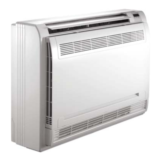
40MBFQ
Floor Console Ductless System
Sizes 09 to 58
NOTE: Read the entire instruction manual before starting the
installation.
NOTE: Image for illustration purposes only. Actual model may be
slightly different.
Installation Instructions
TABLE OF CONTENTS
. . . . . . . . . . . . . . . . . . . . . . . . . . . . . . . . . . . . . . .
. . . . . . . . . . . . . . . . . . . . . . . . . . . . . . . . . . . . . . . . . . .
. . . . . . . . . . . . . . . . . . . . . . . . . . . . . . . . . . . . . .
. . . . . . . . . . . . . . . . . . . . . . . . . . . . . . . . . . . . .
. . . . . . . . . . . . . . . . . . . . . . . . . . . . . . .
. . . . . . . . . . . . . . . . . . . . . . . . . . . . . . . . . . . . . . . .
. . . . . . . . . . . . . . . . . . . . . . . . . . . . . .
. . . . . . . . . . . . . . . . . . . . . . . . .
. . . . . . . . . . . . . . . . . . . . . . . . . . .
. . . . . . . . . .
. . . . . .
. . . . . . . . . . . . . . . . . . . . . . . . .
. . . . . .
. . . . . . . . . .
PAGE
2
3
4
4
5
7
7
7
. .
8
9
11
12
12
12
13
Advertisement
Table of Contents

Related Manuals for International comfort products 40MBFQ


Summary of Contents for International comfort products 40MBFQ
-
Page 1: Table Of Contents
40MBFQ Floor Console Ductless System Sizes 09 to 58 Installation Instructions TABLE OF CONTENTS PAGE SAFETY CONSIDERATIONS ...... -
Page 2: Safety Considerations
SAFETY CONSIDERATIONS WARNING Installing, starting up, and servicing air−conditioning equipment can be hazardous due to system pressures, electrical components, ELECTRICAL SHOCK HAZARD and equipment location (roofs, elevated structures, etc.). Failure to follow this warning could result in personal Only trained, qualified installers and service mechanics should injury or death. -
Page 3: Parts List
PARTS LIST D. Connecting point of refrigerant pipe (D. gas side) Drain point E. Connecting point of refrigerant pipe (E. Liquid side) Sizes 18K - 58K Sizes 09K -12K INDOOR UNIT Air flow louver (at air outlet) Air inlet (with air filter inside) Installation section Wireless remote controller Display panel... -
Page 4: System Requirements
SYSTEM REQUIREMENTS Allow sufficient space for airflow and servicing unit. Piping IMPORTANT: Both refrigerant lines must be insulated separately. S Minimum refrigerant line length between the indoor and outdoor units is 10 ft. (3 m). S Table 2 lists the pipe sizes for the indoor unit. Refer to the outdoor unit installation instructions for other allowed piping lengths and refrigerant information. -
Page 5: Dimensions
DIMENSIONS 8.27(210) 27.56(700) Hanging arm 7.68(195) 0.63(16) Drain pipe Unit: in (mm) Fig. 2 - Indoor Unit Sizes 09−12 Table 3—Indoor Unit Sizes 09−12 UNIT SIZE Depth in. (mm) 8.27 (210) 8.27 (210) Width in. (mm) 27.56 (700) 27.56 (700) Height in. - Page 6 DIMENSIONS (CONT) 1.3in (33mm) 1.57in (40mm) 4.7in (120mm) Outside Air Intake 4.7in (120mm) Fig. 3 - Indoor Unit Sizes 18−58 Table 4—Indoor Unit Sizes 18−58 UNIT SIZE Height in(mm) 9.25(235) 9.25(235) 9.25(235) 9.25(235) 9.25(235) Width in(mm) 42.05(1068) 42.05(1068) 50.59(1285) 64.96(1650) 64.96(1650) Depth in(mm)
-
Page 7: Clearances
CLEARANCES Fig. 4 - Indoor Unit Clearance INSTALLATION LOCATION REQUIREMENTS A location where there are no obstacles near inlet and outlet area. A location which can bear the weight of indoor unit. Hook Do not install indoor units near a direct source of heat such as direct sunlight or a heating appliance. -
Page 8: Indoor Unit Installation Console Sizes 18−58
INDOOR UNIT PREPARATION INDOOR INSTALLATION CONSOLE 1. Open the Front Panel sliding the two stoppers towards the SIZES 18−58 middle of the indoor unit (see Fig. 7). 1. The mounting hooks should be located horizontally and level on the wall or vertical on the ceiling. All minimum clearances should be maintained. -
Page 9: Interconnecting Piping
Handle Yoke Cone Copper pipe Clamp handle Red arrow mark Fig. 17 - Clamp Handle 5. Apply a small amount of refrigerant oil to the flare connection on the tubing. 6. Align the center of the pipes. Fig. 14 - Wall mount installation Indoor unit tubing Flare nut Pipings... - Page 10 CONDENSATE DRAIN CONNECTION ELECTRICAL CONNECTIONS SIZES 09−12 The unit is supplied with a drain connection to connect the drain 1. Remove the installation bearer of the sensing device (see piping. When installing condensate piping, follow these Fig. 22). recommendations: Installation bearer of sensing device Condensate piping should slope downward in the direction of the condensate flow, with a minimum...
-
Page 11: Electrical Data
ELECTRICAL DATA Table 7—Electrical Data Console and Floor Ceiling Size (208/230V) (208/230V) (208/230V) (208/230V) (208/230V) (208/230V) (208/230V) 0.21 0.21 1.11 1.11 1.36 0.94 Input 66.6 66.6 Rated HP 0.027 0.027 0.075 0.075 0.156 0.122 0.218 LEGEND FLA - Full Load Amps CONNECTION DIAGRAMS Fig. -
Page 12: Wireless Remote Control Installation
WIRELESS REMOTE CONTROL START−UP INSTALLATION Test Operation Mounting Bracket (if installed on the wall) Perform a test operation after completing a gas leak and electrical safety check. 1. Use the two screws supplied with the control to attach the mounting bracket to the wall in a location selected by the 1. -
Page 13: Troubleshooting
TROUBLESHOOTING For ease of service, the systems are equipped with a diagnostic If possible, always check the diagnostic codes displayed on the code display LEDs on both the indoor and outdoor units. indoor unit first. The indoor diagnostic display is a combination of flashing LEDs The diagnostic codes displayed in the indoor and outdoor units are on the display panel or the front of the unit. - Page 14 Catalog No: IM-40MBFQ-02 Copyright 2018 CAC / BDP D 7310 W. Morris St. D Indianapolis, IN 46231 Edition Date: 03/18 Manufacturer reserves the right to change, at any time, specifications and designs without notice and without obligations. Replaces: IM-40MBFQ-01...