Table of Contents
Advertisement
Quick Links
Operating Instructions and Parts Manual
™
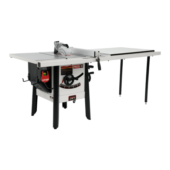
ProShop II
10-inch Table Saw
Model JPS-10TSL
shown with cast wings, 52" rail set, and extension table
JPW Tool Group Hong Kong Limited
98 Granville Road, Tsimshatsui East, Kowloon, Hong Kong, PRC
Part No. M-725000K-RU
www.jettools.com
Edition 4 2/2023
Copyright © 2018 JET
Импортёр в РФ: ООО «ИТА Технолоджи»
105082, Москва, Переведеновский пер., д. 17
www.jettools.ru
Made in Taiwan / Сделано на Тайване
Advertisement
Table of Contents

Related Manuals for Jet ProShop II


Summary of Contents for Jet ProShop II
- Page 1 98 Granville Road, Tsimshatsui East, Kowloon, Hong Kong, PRC Part No. M-725000K-RU www.jettools.com Edition 4 2/2023 Copyright © 2018 JET Импортёр в РФ: ООО «ИТА Технолоджи» 105082, Москва, Переведеновский пер., д. 17 www.jettools.ru Made in Taiwan / Сделано на Тайване...
-
Page 2: Important Safety Instructions
Personal safety • Stay alert, watch what you are doing and use common sense when operating a power tool. Do not use a power tool while you are tired or under the influence of drugs, alcohol or medication. A moment of inattention while operating power tools 1.0 IMPORTANT SAFETY may result in serious personal injury. -
Page 3: Specific Safety Warnings For Table Saws
• operate the power tool. Power tools are For the riving knife and anti-kickback pawls to dangerous in the hands of untrained users. work, they must be engaged in the workpiece. The riving knife and anti-kickback pawls are • Maintain power tools and accessories. Check ineffective when cutting workpieces that are too for misalignment or binding of moving parts, short to be engaged with the riving knife and anti-... - Page 4 • • Provide auxiliary workpiece support to the rear Use extra caution when making a cut into blind and/or sides of the saw table for long and/or areas of assembled workpieces. The protruding wide workpieces to keep them level. A long saw blade may cut objects that can cause kickback.
- Page 5 • Do not use this table saw for other than its intended use. If used for other purposes, JET disclaims any real or implied warranty and holds itself harmless from any injury that may result from that use.
-
Page 6: Table Of Contents
11.2 Lubrication ........................25 11.3 Additional servicing ......................25 12.0 Optional accessories ......................26 13.0 Troubleshooting JPS2 ProShop II ..................27 14.1.1 Motor and Trunnion – Exploded View .................28 14.1.2 Motor and Trunnion – Parts List ..................29 14.2.1 Table and Cabinet– Exploded View ................32... -
Page 7: About This Manual
Whatever accepted methods are used, always make personal safety a priority. If there are questions or comments, please contact your local supplier or JET. JET can also be reached at our web site: www.jettools.com. - Page 8 – always use appropriate the kerf opening in the workpiece during a cutting devices to feed the workpiece through the saw operation. (JET table saws use the superior Riving blade during cutting operations.) Knife system instead.) Kerf: The resulting cut or gap made by a saw Standard Kerf: 1/8”...
-
Page 9: Specifications
5.0 Specifications Table 1 Model number JPS-10TSL JPS-10TSL Stock number 725000K-RU 725000K-3RU Motor and Electricals Motor type Totally enclosed, fan cooled, induction Horsepower 1.5Kw (2HP) 1.87kW (2.5HP) Motor phase 1 PH Motor voltage 230 V 400 V Cycle 50Hz Listed FLA (full load amps) 11 A Motor speed 2800 RPM... - Page 10 = not applicable The specifications in this manual were current at time of publication, but because of our policy of continuous improvement, JET reserves the right to change specifications at any time and without prior notice, without incurring obligations.
-
Page 11: Setup And Assembly
Read understand assembly instructions before attempting assembly. Failure to comply may cause serious injury. 6.0 Setup and assembly 6.1 Shipping contents See Figures 5-1 and 5-2. NOTE: Some parts may have come pre-assembled to the table saw. Table saw with on/off switch (not shown) Blade (preinstalled on saw) Table insert (preinstalled on saw) Arbor wrench (preinstalled on tool holder) -
Page 12: Tools Required For Assembly
6.2 Tools required for assembly Hex (Allen) wrenches: 4, 5, 6mm Open end wrenches: 10, 13mm Cross point (Phillips) screwdriver Straight edge Rubber mallet (or hammer with block of wood) Level Note: A ratchet wrench with sockets will speed assembly time. Additional tools may be needed for adjustments and/or assembly of fence and rails. -
Page 13: Handwheels
5. Repeat above steps for opposite extension wing. Method 2 (Figure 5-6): 1. Follow steps 1 through 3 from Method 1. 2. Position clamps over seam, one at front, one at back of table. Use a pad or flat block beneath clamp jaw to prevent damage to table surface. -
Page 14: Rails And Fence
(not included) and secured with a secure. hose clamp. Note: Dryer vent hose is not acceptable for this purpose. An extensive line of JET dust collectors is available; contact your dealer or visit our website for information. -
Page 15: Blade Guard
Figure 5-10 Figure 5-12 6.15 Blade installation/replacement When installing or changing blades, always disconnect saw from power source. Failure to comply may cause serious injury. 1. Disconnect machine from power source. 2. Using the handwheels, raise blade arbor fully and lock saw at zero-degrees by tightening lock knob at center of handwheel. -
Page 16: Low Profile Riving Knife
Figure 5-14 6.18 Miter gauge See Figure 5-15. Figure 5-13 6.16 Low profile riving knife A low profile riving knife is included with your saw. It mounts and adjusts in the same manner as the standard riving knife. The low profile riving knife sits just below top of blade and is used for making non-through cuts. -
Page 17: Electrical Connections
restart. If overloading happens frequently, consult 7.0 Electrical connections the Troubleshooting section in this manual. The JPS-10TSL table saw is wired for 230-volt only. The table saw comes with a plug designed for use on a circuit with a grounded outlet. Before connecting to power source, be sure switch is in off position. -
Page 18: Adjusting Blade Tilt Stops
Figure 7-1 8.2 Adjusting blade tilt stops Figure 7-3 The 45° and 90° blade tilt stops have been set by 9. Tilt blade to 45° and verify setting in the same the manufacturer, but should be verified by the manner as above. See Figure 7-4. Adjust 45° operator. - Page 19 3. Place a straight edge on table so it rests 3. Use 3mm hex key to loosen two socket head against blade and riving knife. See Figure 7-6. button screws (C, Figure 7-7). This will allow Rotate blade so that top of blade tooth touches the clamp plate (D) to slide back and forth on straight edge.
-
Page 20: Belt Adjustment/Replacement
until it touches the tip of blade, and lock the scale in position. See Figure 7-9. To replace belt, loosen bolt (C) and shift motor 5. Rotate marked tooth (A) so that it is slightly upward to create sufficient slack in belt. Remove above table top at the rear and, using the old belt from pulleys and install new one. -
Page 21: Rip Sawing
• Bevel ripping cuts should always be made with the Where possible, keep your face and body out fence on the right side of saw blade so that the of line with potential kickbacks including when blade tilts away from the fence and minimizes the starting or stopping the machine. -
Page 22: Resawing
Figure 8-4 In ripping, use one hand to hold the board down Figure 8-6 against the fence or fixture, and the other to push it into the blade between blade and fence. If 9.3 Resawing workpiece is narrower than 6" (150mm) or shorter than 12"... -
Page 23: Bevel And Miter Operations
Provide auxiliary support for any workpiece extending beyond the table top with a tendency to sag and lift up off the table. Have the blade extend about 1/8" (3.175mm) above the top of the workpiece. Exposing the blade above this point can be hazardous. Figure 8-8 Figure 8-10 9.5 Bevel and miter operations... -
Page 24: Safety Devices
Have the blade extend only 1/8" (3.175mm) above Never use a dado head in a the top of the workpiece. Exposing the blade above tilted position. Never operate the saw without this point can be hazardous. the blade guard, riving knife and anti-kickback pawls for operations where they can be used. -
Page 25: User-Maintenance
11.0 User-maintenance Always disconnect power to the machine before performing maintenance. Failure to do this may result in serious personal injury. 11.1 Cleaning Clean the JPS2 according to the schedule below to ensure maximum performance. The schedule Figure 9-2 – Push Block Template assumes the saw is being used every day. -
Page 26: Optional Accessories
Contact your dealer to order, or call JET at the 12.0 Optional accessories phone number on the cover. These accessory items, purchased separately, can enhance the functionality of your table saw. # 725004 – Dado Insert for ProShop II... -
Page 27: Troubleshooting Jps2 Proshop Ii
13.0 Troubleshooting JPS2 ProShop II Symptom Possible Cause Correction Motor will not start Low voltage. Check power line for proper voltage. Open circuit in motor or loose Inspect all lead connections on motor for connection. loose or open connections. Motor will not start: fuses Short circuit in line cord or plug. -
Page 28: Motor And Trunnion - Exploded View
14.1.1 Motor and Trunnion – Exploded View... -
Page 29: Motor And Trunnion - Parts List
14.1.2 Motor and Trunnion – Parts List Index No Part No Description Size 1 ....6291479 ....Key, Dbl Rd Hd ............5x5x30mm ....1 2 ....JPS10TSC-102 ..Motor Pulley ....................1 3 ....TS-2276081 ....Socket Set Screw ............ M6-1.0Px8..... 2 6 .... - Page 30 Index No Part No Description Size 59 ....TS-1504071 ....Socket Head Cap Screw.......... M8-1.25Px35....2 60 ....JPS10TSC-160 ..Hose ................ 2.5 ......... 1 61 ....JWP12-118 ....Key, Dbl Rd Hd ............4x4x8mm ...... 2 62 ....JPS10TSC-162 ..Plate....................... 1 63 ....
- Page 31 Index No Part No Description Size 112 .... JPS10TSC-1112 ..Hose Clamp ............. 60-80mm ....... 1 113 .... JPS10TSC-1113A ..Dust Chute ............... 1-1/2”to 4" ..... 1 114....JPS10TS-SHA ... Side Handwheel Assembly (#114-1, 93-1, 93-2, 93-4) ........1 114-1 ..JPS10TS-168 .... Handwheel (Not shown) ................1 115 ....
- Page 32 14.2.1 Table and Cabinet– Exploded View...
- Page 33 Size 1 ....JPS10TSC-201A ..Cabinet ......................1 2 ....725002 ...... ProShop II Stamped Steel Wings (includes #3,4).......... 2 ....725003 ...... ProShop II Cast Wings (includes #3,4) ............2 3 ....TS-1504041 ....Socket Head Cap Screw.......... M8-1.25x20 ....8 4 ....
-
Page 34: Stand Assembly - Exploded View
14.3.1 Stand Assembly – Exploded View 14.3.2 Stand Assembly – Parts List Index No Part No Description Size 1 ....JPS10TSC-301 ..Leg ......................... 4 2 ....TS-1550041 ....Flat Washer ............. M6 ......... 8 3 ....TS-1482031 ....Socket Head Cap Screw.......... M6-1.0x16 ..... 8 4 .... -
Page 35: Switch Assembly - Exploded View
14.4.1 Switch Assembly – Exploded View 14.4.2 Switch Assembly – Parts List Index No Part No Description Size 1 ....JPS10TSC-401A ..Magnetic Switch Kit ..........230V......1 ....JPS10TSC-401ARU.. Magnetic Switch Kit ..........400V......1 2 ....JPS10TSC-402 ..Switch Box ............... 230V......1 .... -
Page 36: Blade Guard Assembly - Exploded View
14.5.1 Blade Guard Assembly – Exploded View... -
Page 37: Blade Guard Assembly - Parts List
14.5.2 Blade Guard Assembly – Parts List Index No Part No Description Size 1 ....JPS10TSC-501 ..Right Side Blade Guard ................. 1 2 ....JPS10TSC-502 ..Screw ......................4 3 ....JPS10TSC-503 ..Left Side Blade Guard ................... 1 4 .... -
Page 38: Miter Gauge Assembly - Exploded View
14.6.1 Miter Gauge Assembly – Exploded View 14.6.2 Miter Gauge Assembly – Parts List ....JPS10TSC-MG ..Miter Gauge Assembly (#1 thru 13) ............... 1 1 ....JPS10TS-327 .... Handle ......................1 2 ....TS-0680041 ....Flat Washer ............. 3/8” ........ 1 3 .... -
Page 39: Electrical Connections For Jps-10Tsl
15.0 Electrical Connections for JPS-10TSL... - Page 40 427 New Sanford Road LaVergne, Tennessee 37086 Phone: 800-274-6848 www.jettools.com...