Table of Contents
Advertisement
This Manual is Bookmarked
Operating Instructions and Parts Manual
18-Inch, 20-Inch Band Saw
Models: JWBS-18QT, -18QT-3, -20QT-3, -20QT-5
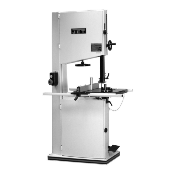
JWBS-18QT
JWBS-20QT
WALTER MEIER (Manufacturing), Inc.
427 New Sanford Road
LaVergne, TN 37086-4184, USA
Part No. M-710750B
Ph.: 800-274-6848
Revision C 10/09
www.waltermeier.com
Copyright © 2009 Walter Meier (Manufacturing), Inc.
Advertisement
Table of Contents

Related Manuals for Jet JWBS-18QT


Summary of Contents for Jet JWBS-18QT
- Page 1 This Manual is Bookmarked Operating Instructions and Parts Manual 18-Inch, 20-Inch Band Saw Models: JWBS-18QT, -18QT-3, -20QT-3, -20QT-5 JWBS-18QT JWBS-20QT WALTER MEIER (Manufacturing), Inc. 427 New Sanford Road LaVergne, TN 37086-4184, USA Part No. M-710750B Ph.: 800-274-6848 Revision C 10/09 www.waltermeier.com...
-
Page 2: Warranty And Service
Walter Meier is consistently adding new products to the line. For complete, up-to-date product information, check with your local Walter Meier distributor, or visit jettools.com. WARRANTY JET products carry a limited warranty which varies in duration based upon the product (MW = Metalworking, WW = Woodworking). WHAT IS COVERED? This warranty covers any defects in workmanship or materials subject to the exceptions stated below. -
Page 3: Table Of Contents
Warranty and Service..........................2 Table of Contents ..........................3 Warning .............................4 Introduction ............................6 Specifications .............................6 Grounding Instructions ........................7 Model JWBS-18QT..........................7 Models JWBS-18-3, -20QT-3, -20QT-5 .....................8 Unpacking ............................9 Contents of Shipping Container ......................9 Assembly ............................10 Handwheel............................ 10 Mounting the Table ........................10 Rail Assembly .......................... -
Page 4: Warning
Warning 1. Read and understand the entire owner's manual before attempting assembly or operation. 2. Read and understand the warnings posted on the machine and in this manual. Failure to comply with all of these warnings may cause serious injury. 3. -
Page 5: Save These Instructions
20. Make your workshop child proof with padlocks, master switches or by removing starter keys. 21. Give your work undivided attention. Looking around, carrying on a conversation and “horse-play” are careless acts that can result in serious injury. 22. Maintain a balanced stance at all times so that you do not fall or lean against the blade or other moving parts. -
Page 6: Introduction
Introduction This manual is provided by Walter Meier (Manufacturing), Inc., covering the safe operation and maintenance procedures for JET model JWBS-18QT and JWBS-20QT series band saws. This manual contains instructions on installation, safety precautions, general operating procedures, maintenance instructions and parts breakdown. This machine has been designed and constructed to provide years of trouble free operation if used in accordance with instructions set forth in this manual. -
Page 7: Grounding Instructions
Repair or replace a damaged or worn cord immediately. Model JWBS-18QT Model JWBS-18QT Band Saw has a 1-3/4 HP 1 phase motor and is wired from the factory for 115 volt operation, but can be rewired for 220 volts. -
Page 8: Models Jwbs-18-3, -20Qt-3, -20Qt-5
Models JWBS-18-3, -20QT-3, -20QT-5 Recommended Model Voltage Circuit* Band saw models JWBS-18QT-3, JWBS-20QT- 115V JWBS-18QT 3 and JWBS-20QT-5 are wired from the factory 710750B for 230 volt operation. Refer to Specifications for 230V phase and HP ratings. JWBS-18QT-3 710751B A plug is not included. You may either install a JWBS-20QT-3 plug or “hard-wire”... -
Page 9: Unpacking
01 0Lock Handle (L) – JWBS-20QT only 01 0Resaw Post Lock Knob (M) 01 0Lock Knob (N) – JWBS-20QT only 02 0Lock Knob (N) – JWBS-18QT only Fence Hardware Bag 04 5/16-18x3/4 Socket Head Cap Screws (P) 04 5/16 Flat Washers (Q) -
Page 10: Assembly
4. Line up the table (G) to the trunnions so that the bolts (F ) feed through the support bracket (E For band saw model JWBS-18QT Secure the table with two lock knobs (H). For band saw model JWBS-20QT Secure the table with lock knob (H) to bolt F and lock handle (J) to bolt F 5. -
Page 11: Rail Assembly
Rail Assembly Referring to Figure 7: 1. Attach the front rail (F) to the cast iron table with two 1/4” x 5/8” hex cap screws, two 1/4” lock washers, and two 1/4” flat washers. The screws should be in approximately the center of the slot. - Page 12 Fence Adjustment 2. Place the fence assembly onto the guide rail (D, Fig. 9) and against the edge of the miter slot (C, Fig. 9). The hook at the rear of the fence should fit under the rear rail (see Figure 12).
-
Page 13: Resaw Guide
Adjusting Clearance between Fence and Table Referring to Figures 11 and 12: Check the clearance between the table and the fence. The fence should not rub against the table surface but be slightly above it. This gap should be the same at the front of the table as it is at the rear. Figure 11 If the gap between fence and table is not consistent, loosen either of the hex nuts on the... -
Page 14: Adjustments
Adjustments Table Tilt Referring to Figure 14: 1. Disconnect machine from power source. 2. Loosen the lock knob(s)/lock handle (G). 3. Tilt table up to 45 degrees to the right, or up to 10 degrees to the left. 4. Tighten the lock knob(s)/lock handle. Note: Table stop bolt (F, Fig. -
Page 15: Installing/Changing Blades
Installing/Changing Blades Disconnect machine from power source. Blade teeth are sharp, use care when handling the blade. Failure to comply may cause serious injury. 1. Disconnect machine from power source. 2. Place the mode selection lever (J, Fig. 18) in the Full Release (Blade Change) position. -
Page 16: Blade Tension
Initially, set the blade tension to correspond to the width of your blade. The JWBS-18QT comes with a 3/4" blade so the tension should be set at 3/4" when using this blade. -
Page 17: Overview - Bearing Adjustments
Overview – Bearing Adjustments Thrust (back support) bearing are located behind the saw blade and provide support to the back of the blade when the saw is in operation. Guide bearings are located on either side of the saw blade and provide stability for the blade when the saw is in operation. -
Page 18: Lower Bearing Adjustments
Lower Bearing Adjustments Unplug the machine from power source before making any adjustments! Blade teeth are sharp - use care when working near the saw blade. Failure to comply may cause serious injury. Note: Blade tension and tracking must be properly adjusted prior to bearing guide setup. -
Page 19: Blade Lead
Blade Lead Blade drift (also known as lead or fence drift) is a problem that may occur when the blade begins to wander off the cutting line even when the band saw fence is being used. Figure 24 shows an example of blade lead. -
Page 20: Changing The Blade Speed
Disconnect machine from power source before making any adjustments. The JWBS-18QT and -20QT band saw has two blade-speed options which is determined by the position of the pulley drive belt. Refer to the Specifications section (page 6) for speed specs. -
Page 21: Replacing The Poly V-Belt
Replacing the Poly V-Belt Disconnect machine from power source before making any adjustments. 1. Place the mode selection lever (J, Fig. 18) in the Full Release position. Referring to Figure 25: 2. Loosen the lock handle (A) that secures the motor (C). -
Page 22: Pulley Alignment
Pulley Alignment The pulley alignment is done in conjunction with the poly V-belt replacement. If you are just beginning the alignment, start with the Replacing the Poly V-Belt section (previous page. If you were directed here, proceed as follows: 1. Uses a straight edge placed against the wheel pulley and motor pulley and refer to Figure 29 to determine if alignment is necessary. -
Page 23: Operating Controls
Operating Controls Safety Key – The magnetic Start/Stop switch Start/Stop Switch comes equipped with a magnetic safety key. The switch shown in Figure 30 is used on model When in position on the switch as shown in JBWS-18QT band saw. Figure 31, the magnetic safety key trips a relay which will allow the machine to start and stop Press the green on button (A, Fig. -
Page 24: Operation
Ripping Operation Ripping cutting lengthwise down workpiece, and with the grain (of wood stock). General Procedure See Figure 34. 1. Make sure the blade and upper and lower bearings are properly adjusted for tension and tracking. 2. Adjust blade guide assembly so that the guide bearings are just above the workpiece (about 3/16”) allowing minimum exposure to the blade. -
Page 25: Resawing
Resawing the tip of the tooth. Generally, wider blades are used for ripping or making straight cuts; Resawing is the process of slicing stock to narrower blades are often used when the part reduce its thickness, or to produce boards that being cut has curves with small radii. -
Page 26: Blade Breakage
Blade Do not let saw dust build up in the upper and Selection Guide on page 27. lower wheel housings. Vacuum out frequently. Connect the band saw to a JET dust collection When cutting, system. -
Page 27: Blade Selection Guide
Blade Selection Guide Identify the material and thickness of your workpiece. The chart will show the recommended PITCH, blade TYPE, and FEED RATE. Key: H – Hook L – Low S – Skip M – Medium R – Regular H – High Example: 10/H/M means 10 teeth per inch / Hook Type Blade / Medium Feed Workpiece Thickness Material/s... -
Page 28: Troubleshooting
Troubleshooting Trouble Probable Cause Remedy Saw unplugged Check plug connections Saw stops or will not Fuse blown, or circuit breaker tripped Replace fuse, or reset circuit breaker start Cord damaged Replace cord Check blade with square and adjust Stop not adjusted correctly stop Does not make accurate 45... -
Page 29: Parts
Parts Replacement Parts Replacement parts are listed on the following pages. To order parts or reach our service department, call 1-800-274-6848, Monday through Friday (see our website for business hours, www.waltermeier.com). Having the Model Number and Serial Number of your machine available when you call will allow us to serve you quickly and accurately. - Page 30 37 .... TS-0590061 ....Wing Nut ............5/16-18 ...... 1 38 .... JWBS18-138 ...Lock Knob ............5/16 ......1 39 .... JWBS18DXA-139 ..Upper Front Door................1 40 .... JWBS18-140 ...JET Nameplate................... 1 41 .... JWBS18-141 ...Warning Label ..................1 42 .... JWBS18-142 ...Bolt ....................1 43 ....
- Page 31 Index No. Part No. Description Size 62 .... TS-1540031 ....Hex Nut............M5 ......1 63 .... JWBS18DXA-163 ..Blade Warning Label................1 64 .... JWBS18DXA-164 ..Grip ....................1 65 .... PM2000-298....Safety Key for Magnetic Switch ......for 3HP ...... 1 66 .... PM2000-293....Magnetic Switch ..........for 3HP ...... 1 67 ....
- Page 32 Lower Wheel and Motor Assembly (18QT) Index No. Part No. Description Size 1 ....JWBS18-201N ..Bearing Base..................1 2 ....JWBS20-62 .....Adjusting Bolt ..................4 3 ....TS-0720091 ....Lock Washer ............3/8 ......4 4 ....TS-0060081 ....Hex Cap Screw ..........3/8-16 x 1-3/4 ..... 4 5 ....
- Page 33 Index No. Part No. Description Size 53 .... TS-0560071 ....Hex Nut............#10-24 ....... 2 54 .... JWBS18DX-254 ..Plastic Washer ..........5/16 ......1 55 .... TS-0720081 ....Lock Washer ............5/16 ......2 56 .... TS-0561021 ....Hex Nut............5/16-18 ...... 2 62 .... JWBS18DXA-262 ..Grip ....................1 63 ....
- Page 34 Blade Guide Assembly (18QT) Index No. Part No. Description Size 1 ....TS-0051051 ....Hex Cap Screw ..........5/16-18 x 1 ....4 2 ....TS-0720081 ....Lock Washer ............5/16 ......4 3 ....TS-0680031 ....Flat Washer............5/16 ......8 4 ....JWBS18DX-304 ..Guide Bar Bracket ................1 5 ....
- Page 35 Index No. Part No. Description Size 59 .... JWBS18DX-359 ..Locking Handle................... 1 60 .... JWBS18DX-360 ..Shaft ....................1 61 .... JWBS18DX-361 ..Adjusting Screw .................. 1 62 .... JWBS18DX-362 ..Adjusting Bracket................1 63 .... JWBS18DX-363 ..Nut ....................1 64 .... TS-0267021 ....Set Screw ............1/4-20 x 1/4 ....1 65 ....
- Page 36 49 .... JWBS18-449E ..Resaw Post ..................1 50 .... JWBS18-450 ...Lock Knob ..................1 51 .... JWBS18-451 ...JET Fence Label ................1 52 .... TS-2210651 ....Hex Cap Screw ..........M10 x 65 ....1 53 .... TS-1551041 ....Lock Washer ............M6 ......6 54 ....
- Page 37 Index No. Part No. Description Size 59 .... JWBS18DX-459 ..C-Ring .............S-10......1 60 .... JWBS18DX-460 ..Link Chain ..................1 61 .... TS-0680031 ....Flat Washer............5/16 ......2 62 .... 2013-285....End Cover ..................2 ....JWBS18-MGCP ..Miter Gauge Assembly ................ 1 ....JWBS18QT-FCP ..Fence Assembly ................. 1...
- Page 38 38 .... PM2000-293....Magnetic Switch ..........3HP, 1Ph ....1 ....PM2000-293A ..Magnetic Switch ..........5HP, 1Ph ....1 39 .... JWBS20QT-539 ..Upper Front Door................1 40 .... JWBS18-140 ...JET Plaque ..................1 41 .... JWBS18-141 ...Warning Label ..................1 42 .... JWBS20-542 ...Door Stud................... 1 43 ....
- Page 39 Index No. Part No. Description Size 57 .... 2013-333....Spacer ....................1 58 .... JWBS18DXA-164 ..Grip ....................1 59 .... JWBS18DXA-163 ..Blade Warning Label................1 60 .... JWBS20QT-560 ..Tension Status Label ................1 61 .... JWBS18DXA-168 ..Spring Plate ..................1 62 .... TS-081C052 ....Screw ..............#10-24 x 3/4 ....1...
- Page 40 Lower Wheel and Motor Assembly (20QT) Index No. Part No. Description Size 1 ....JWBS20-201 ...Bearing Base..................1 2 ....JWBS20-62 .....Adjusting Bolt ..................4 3 ....TS-0720091 ....Lock Washer ............3/8 ......6 4 ....TS-0060111 ....Hex Cap Screw ..........3/8x2-1/2 ....4 5 ....
- Page 41 Index No. Part No. Description Size 39 .... TS-069204 ....Flat Washer............#10 ......4 40 .... JWBS18-240 ...Brush ....................1 41 .... TS-0720051 ....Lock Washer ............#10 ......2 43 .... JWBS18DX-243A ..Motor Cord ............for 3HP ...... 1 ....JWBS20QT-243 ..Motor Cord ............for 5HP ...... 1 44 ....
- Page 42 Lower Wheel and Motor Assembly (20QT)
- Page 43 Blade Guide Assembly (20QT) Index No. Part No. Description Size 1 ....TS-0051051 ....Hex Cap Screw ..........5/16-18x1 ....4 2 ....TS-0720081 ....Lock Washer ............5/16 ......4 3 ....TS-0680031 ....Flat Washer............5/16 ......8 4 ....JWBS20-304 ...Guide Bar Bracket ................1 5 ....
- Page 44 Index No. Part No. Description Size 60 .... JWBS20-360 ...Bracket ....................1 61 .... JWBS18DX-361 ..Adjusting Screw .................. 1 62 .... JWBS18DX-362 ..Adjusting Bracket................1 63 .... JWBS18DX-363 ..Nut ....................1 64 .... TS-0267021 ....Set Screw ............1/4-20x1/4 ....1 65 .... JWBS18DX-365 ..Set Screw, Special................1 66 ....
- Page 45 Blade Guide Assembly Lower Bearing Guide Upper Bearing Guide...
- Page 46 50 .... JWBS20-450 ...Lock Knob ..................1 ....JWBS18-MGCP ..Miter Gauge Assembly ................ 1 ....JWBS20QT-FCP ..Fence Assembly ................. 1 51 .... JWBS18-451 ...JET Fence Label ................1 52 .... TS-1550041 ....Flat Washer............M6 ......6 53 .... TS-1551041 ....Lock Washer ............M6 ......6 54 ....
- Page 47 Index No. Part No. Description Size 57 .... TS-0051091 ....Hex Cap Screw ..........5/16-18x2 ....2 58 .... 40-0260....Wrench ....................1 59 .... JWBS18DX-459 ..C-Ring .............S-10......1 60 .... JWBS18DX-460 ..Link Chain ..................1 61 .... TS-0680031 ....Flat Washer............5/16 ......6 62 ....
-
Page 48: Electrical Connections
Electrical Connections 1 3/4 HP, 1Ph, 115V Band Saw Model No.: JWBS-18QT-1 (SN 710750B) 3HP, 1 Phase 1-3/4 HP, 1Ph, 230V Band Saw Model No.: JWBS-18QT-1 (SN 710750B) -
Page 49: Magnetic Switch
3 HP, 1Ph, 230V Band Saw Model No.: JWBS-18QT-3 (SN 710751B) Magnetic Switch Electrical Board WHITE YELLOW BLACK 300MFD 125VAC 60uF 250WVAC Motor... - Page 50 3 HP, 1Ph, 230V Band Saw Model No.: JWBS-20QT-3 (SN708754B) Magnetic Switch Electrical Board WHITE YELLOW BLACK 300MFD 125VAC 60uF 250WVAC Motor...
- Page 51 5 HP, 1Ph, 230V (Band Saw Model No.: JWBS-20QT-5, SN 708755B) Magnetic Switch Electrical Board WHITE YELLOW BLACK 300MFD 250VAC 50uF 450WVAC Motor...
- Page 52 WALTER MEIER (Manufacturing), Inc. 427 New Sanford Road LaVergne, TN 37086-4184, USA Phone: 800-274-6848 www.waltermeier.com...