Table of Contents
Advertisement
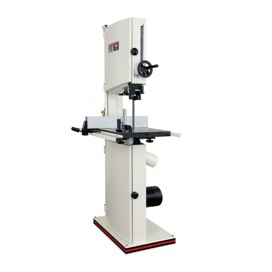
JWBS-16 Woodworking Bandsaw
(shown with optional accessory rip fence, rails and resaw attachment 708747 and miter gauge 708716)
JET
WMH Tool Group
www.wmhtoolgroup.com
OWNER'S MANUAL
P.O. BOX 1349
Auburn, WA 98071-1349
e-mail
jet@wmhtoolgroup.com M-708749 04/02
Phone: 253-351-6000
Fax: 1-800-274-6840
Advertisement
Table of Contents

Related Manuals for Jet JWBS-16


Summary of Contents for Jet JWBS-16
- Page 1 OWNER'S MANUAL JWBS-16 Woodworking Bandsaw (shown with optional accessory rip fence, rails and resaw attachment 708747 and miter gauge 708716) WMH Tool Group www.wmhtoolgroup.com P.O. BOX 1349 Phone: 253-351-6000 Auburn, WA 98071-1349 Fax: 1-800-274-6840 e-mail jet@wmhtoolgroup.com M-708749 04/02...
-
Page 2: Warranty
This manual has been prepared for the owner and operators of a JET JWBS-16. Its purpose, aside from machine operation, is to promote safety through the use of accepted correct operating and maintenance procedures. Completely read the safety and maintenance instructions before operating or servicing the machine. -
Page 3: Warnings
20. Use suitable support if stock does not have a flat surface. 21. Hold material firmly against the table. 22. Saw teeth must point down toward the table. 23. Some dust created by power sanding, sawing, grinding, drilling and other construction activities contains chemicals known to cause cancer, birth defects or other reproductive harm. -
Page 4: Grounding Instructions
Grounding Instructions Caution: This tool must be grounded while in use to protect the operator from electric shock. In the event of a malfunction or breakdown, grounding provides a path of least resistance for electric current to reduce the risk of electric shock. This tool is equipped with an electric cord having an equipment-grounding conductor and a grounding plug. -
Page 5: 230 Volt Operation
230 Volt Operation If 230V, single phase operation is desired, the following instructions must be followed: 1. Disconnect the machine from the power source. 2. This bandsaw is supplied with four motor leads that are connected for 115V operation, as shown in Figure A. -
Page 6: Table Of Contents
Maintenance... 16 Available Accessories... 16 Troubleshooting... 17 Part’s Breakdowns and Part’s List ... 18-29 Wiring Diagram ... 30 Specifications: JWBS-16 Stock Number... 708749 Cutting Capacity (height) ...10” Cutting Capacity (width)...16” Maximum Rip Left of Blade w/Fence ...14-1/4” Blade Length ... 123”... -
Page 7: Contents Of Shipping Container
1. 10/12mm Wrench Unpacking 1. Remove the packing material from the bandsaw. 2. Move the saw to its permanent working location. The site should be dry, well lit, and have enough room to handle long stock and the service and/or adjustment of the machine from any side. -
Page 8: Assembly And Setup
3. If adjustment is necessary, loosen the wing nut (G, Fig. 2) at the top rear of the saw. 4. Adjust tracking by turning the knob (H, Fig. 2) in 1/4 turn increments. Rotate the wheel forward, and observe the position of the blade on the wheel. -
Page 9: Upper Blade Guide Adjustment
Disconnect machine from the power source, unplug before making any adjustments! Blade teeth are sharp! Use care when working near the saw blade. Failure to comply may cause serious injury! 1. Blade tension and tracking must be properly adjusted prior to blade guide setup. -
Page 10: Mounting The Table
1. Remove the table insert (A, Fig. 5) and table pin (B, Fig. 5). 2. Slide saw blade through slot in table where the table pin was located. Rotate the table 90 degrees so that the miter slot is parallel to the blade, and to the right of the blade when facing the bandsaw. -
Page 11: Rail Assembly
Rail Assembly (optional accessory) 1. Attach the front rail (A, Fig. 8) to the cast iron table with two 1/4” x 5/8” hex cap bolts, two 1/4” lock washers, and two 1/4” flat washers. Bolts should be in approximately the center of the slot. Hand tighten only at this time. -
Page 12: Resaw Guide
4. Check the clearance between the table and the fence. The gap should be the same at the front of the table as it is at the rear. If the gap width is different, adjust the foot at the rear of the fence until the gap width is the same, Figure 11. -
Page 13: Tilting The Table
Tilting the Table 1. Disconnect the machine from the power source, unplug. 2. Loosen the lock knobs (A, Fig. 13). 3. Tilt table up to 45 degrees to the right, or up to 10 degrees to the left. 4. Tighten the lock knobs. Note: Table stop bolt (B, Fig. -
Page 14: Changing Blades
WARNING Disconnect machine from the power source, unplug! Blade teeth are sharp! Use care when handling the saw blade. Failure to comply may cause serious injury! 1. Remove the table insert (A, Fig. 16), and table pin (B, Fig. 16). -
Page 15: Replacing Belt
Replacing V-Belt 1. Disconnect the machine from the power source. 2. Release blade tension by turning blade tension hand wheel clockwise. 3. Release belt tension by loosening the two hex cap bolts (A, Fig. 19). Raise the motor and tighten hex cap bolts to take the tension off the belt. -
Page 16: Electrical Connections
All electrical connections must be done by a qualified electrician! Failure to comply may result in loss of property and/or serious injury! JWBS-16 is rated at 1-1/2 HP, 1Ph, 115V/230V, prewired 115V. The bandsaw comes with a 115V plug (A, Fig. 22). -
Page 17: Troubleshooting
Trouble Saw stops or will not start Does not make accurate 45 or 90 cuts Blade wanders during cut Saw makes unsatisfactory cuts Blade does not come up to speed Saw vibrates excessively Troubleshooting Possible Cause 1. Saw unplugged 2. Fuse blown or circuit breaker tripped 3. -
Page 18: Part's Breakdowns And Part's List
Upper Wheel Assembly... - Page 19 Index Part 1...JWBS16-101... Saw Body ..1 2...TS-0152011 ... Carriage Bolt ... 5/16-18 x 1” ... 6 3...JWBS18-103... Upper Wheel Bracket ..2 4...TS-0680031 ... Flat Washer... 5/16 ... 6 5...TS-0720081 ... Lock Washer ... 5/16 ... 6 6...TS-0561021 ...
- Page 20 Index Part ...709577...Carbide Embedded Blade 123" x 3/8" x 0.025" 4 Skip ..709578...Carbide Embedded Blade 123" x 1/2" x 0.025" 3 Hook ..709579...Carbide Embedded Blade 123" x 5/8" x 0.025" 3 Hook ... 37 ...TS-0590061 ... Wing Nut ... 5/16 ... 1 38 ...JWBS18-138...
- Page 21 Lower Wheel and Motor Assembly...
- Page 22 Index Part 1...JWBS18-201N ... Bearing Base..1 2...JWBS20-62... Adjusting Bolt ..4 3...TS-0720091 ... Lock Washer ...3/8 ... 4 4...TS-0060081 ... Hex Cap Bolt ...3/8 x 1-3/4... 4 5...BB-6204ZZ ... Ball Bearing...6204... 1 6...JWBS18-206N ... Spindle ..1 7...JWBS18-207...
- Page 23 Index Part Description Size Qty. 48 ...JWBS18-39A ... Door Hinge Pin ..2 49 ...JWBS16-249... Cast Foot..2 50 ...TS-0060171 ... Hex Cap Bolt ...3/8-16 x 4... 4 51 ...JWBS16-251... Flat Washer (plastic) ...3/8 ... 4...
- Page 24 Blade Guides Assembly...
- Page 25 Blade Guides Assembly Index Part Description Size Qty. 1...TS-0051051 ... Hex Cap Bolt ...5/16 x 1... 4 2...TS-0720081 ... Lock Washer ...5/16... 4 3...TS-0680031 ... Flat Washer...5/16... 8 4...JWBS18-304... Guide Bar Bracket ..1 5...JWBS18-305... Worm ..1 6...JWBS18-306...
- Page 26 Table Assembly...
- Page 27 Index Part 1...JWBS16-401... Table..1 2...JWBS20-144... Table Insert ..1 3...JWBS20-145... Roll Pin ...3 x 10... 1 4...JWBS18-448... Table Pin..1 5...JWBS18-408N ... Trunnion Support Bracket ..1 6...TS-0051071 ... Hex Cap Bolt ...5/16 x 1-1/2... 4 7...TS-0720081 ...
- Page 28 Fence & Miter Assembly (optional accessory)
- Page 29 Fence & Miter Assembly (optional accessory) Index Part 1...JWBS18-401... Lock Knob ..1 2...TS-0680021 ... Flat Washer...1/4 ... 11 3...JWBS18-403... Miter Gauge Body ..1 4...200156... Guide Disc..1 5...JWBS18-405... Pan Head Screw...M6 x 8... 1 6...JWBS18-406... Pointer..1 7...JWBS18-407...
-
Page 30: Wiring Diagram
Wiring Diagram...