Fluke 175, 177, 179 - True-rms Multimeter Manual
- User manual (28 pages) ,
- Calibration information manual (23 pages) ,
- Supplement manual (3 pages)
Advertisement
- 1 Introduction
- 2 Contact Fluke
- 3 Safety Information
- 4 Unsafe Voltage
- 5 Product Disposal
- 6 Test Lead Alert
- 7 Terminals
- 8 Product Buttons
- 9 Rotary Switch Positions
- 10 Display
- 11 Battery Saver (Sleep Mode)
- 12 MIN MAX AVG Recording Mode
- 13 Display HOLD and AutoHOLD Modes
- 14 Manual Range and Autorange
- 15 Power-Up Options
- 16 Basic Measurements
- 17 Measure AC and DC Voltage
- 18 Measure Resistance
- 19 Measure Capacitance
- 20 Test for Continuity
- 21 Measure Temperature (179 Only)
- 22 Test Diodes
- 23 Measure AC or DC Current
- 24 AC Zero Input Behavior of True-rms Meters
- 25 Measure Frequency
- 26 AC/DC Voltage Frequency
- 27 AC Current Frequency
- 28 Use the Bar Graph
- 29 Maintenance
- 30 Clean the Product
- 31 Test the Fuses
- 32 Replace the Battery and Fuses
- 33 Specifications
- 34 Electrical Specifications
- 35 Documents / Resources
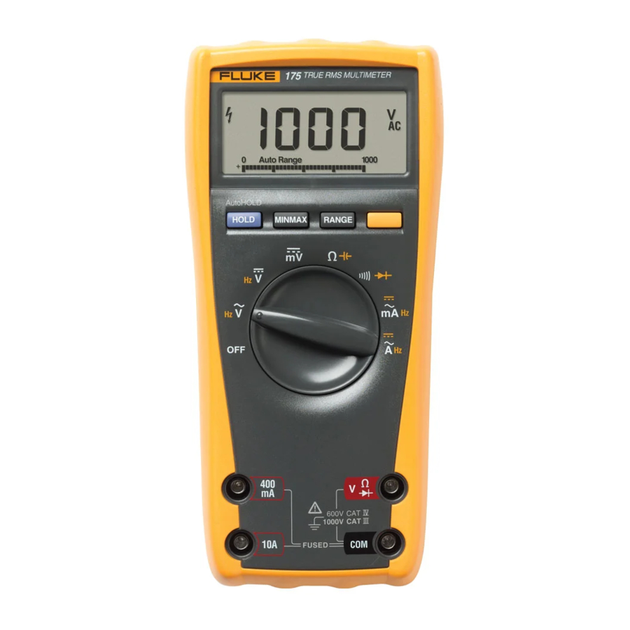
Introduction
The Fluke 175, 177, and 179 are battery-powered, True-rms multimeters (the Product) with a 6000-count, 3 3/4-digit display and a bar graph. This manual applies to all three models. All figures show the 179.
Contact Fluke
Fluke Corporation operates worldwide. For local contact information, go to our website: www.fluke.com
To register your product, view, print, or download the latest manual or manual supplement, go to our website.
+1-425-446-5500
fluke-info@fluke.com.
Safety Information
General Safety Information in the printed Safety Information document that ships with the Product. It can also be found online at www.fluke.com. More specific safety information is listed in this manual where applicable.
In this manual, a Warning identifies conditions and procedures that are dangerous to the user. A Caution identifies conditions and procedures that can cause damage to the Product or the equipment under test.
Unsafe Voltage
During a voltage measurement, the Product alerts you to the presence of a potentially hazardous voltage. When the Product detects a voltage ≥30 V or a voltage overload (0L), the Y symbol shows on the display to alert you to the presence of a potentially hazardous voltage.
Product Disposal
Dispose of the Product in a professional and environmentally sound manner:
- Delete personal data on the Product before disposal.
- Remove batteries that are not integrated into the electrical system before disposal and dispose of batteries separately.
- If this Product has an integral battery, put the entire Product in the electrical waste.
Test Lead Alert
To remind you to check that the test leads are in the correct terminals, LEAd momentarily shows on the display when you move the rotary switch to or from the mA or A position.

Attempting to make a measurement with a test lead in an incorrect terminal might blow a fuse, damage the Product, and cause serious personal injury.
Terminals
Table 1 shows the terminals on the Product.
Table 1. Terminals
 | |
| Item | Description |
| 1 | Input terminal for ac and dc milliamp measurements to 400 mA and frequency measurements. |
| 2 | Input terminal for ac and dc current measurements to 10 A and frequency measurements. |
| 3 | Input terminal for voltage, continuity, resistance, diode, capacitance, frequency, and temperature (179 only) measurements. |
| 4 | Common (return) terminal for all measurements. |
Product Buttons
Table 2 identifies the basic functions of the buttons on the Product. The buttons have other functions described later in the manual.
Table 2. Product Buttons
 | |
| Item | Description |
| 1 | Toggles the backlight on and off. The backlight automatically turns off after 2 minutes (177 and 179 only). |
| 2 | In MIN MAX AVG mode, push to pause or continue MIN MAX AVG recording. In the Display HOLD mode, the Product holds the reading on the display. In the AutoHOLD mode, the Product holds the reading on the display until it detects a new stable reading. Then the Product beeps and displays the new reading. |
| 3 | Activates MIN MAX AVG mode. |
| 4 | Toggles between Auto Range and Manual Range modes. In Manual Range mode, increments the range. After the highest range, the Product wraps to the lowest range. |
| 5 | (Yellow button) Selects alternate measurement functions on a rotary switch setting, for example, to select dc mA, dc A, Hz, temperature (179 only), capacitance, diode test. |
Rotary Switch Positions
Table 3 identifies the switch positions on the Product.
Table 3. Rotary Switch Positions
| Switch Position | Measurement Function |
 | AC voltage from 30.0 mV to 1000 V. Frequency from 2 Hz to 99.99 kHz. |
 | DC voltage 1 mV to 1000 V. Frequency from 2 Hz to 99.99 kHz. |
 | DC mV 0.1 mV to 600 mV. −40°C to +400°C. |
 | Beeper turns on at <25 Ω and turns off at >250 Ω. Diode test. Displays 0L above 2.4 V. |
 Hz | AC A from 0.300 A to 10 A. >10.00, display flashes. Frequency of ac A 2 Hz to 30 kHz. |
 | Ohms from 0.1 Ω to 50 MΩ. Farads from 1 nF to 9999 μF. |
 | AC mA from 3.00 mA to 400 mA. DC mA from 0.01 mA to 400 mA. Frequency of ac mA 2 Hz to 30 kHz. |
 Note: AC voltage and current AC-coupled, true-rms, up to 1 kHz.
Display
Table 4 shows the items on the Product display.
Table 4. Display
 | ||
| Item | Symbol | Description |
| 1 |  | Continuity test. |
| 2 |  | Diode test. |
| 3 |  | Negative readings. |
| 4 |  | Unsafe voltage. Voltage ≥30 V, or voltage overload (0L). |
| 5 |
| Display HOLD is enabled. Display freezes present reading. AutoHOLD is enabled. Display holds present reading until it detects new stable input. Then the Product beeps and displays the new reading. |
| 6 |  | MIN MAX AVG enabled. Maximum, minimum, average or present reading. |
| 7 | nμ F, °F, °C mVA,  , kHz , kHz | Measurement units. |
| 8 | DC, AC | Direct current, alternating current. |
| 9 |  | Low battery. Replace battery. |
| 10 | 610000mV | All possible ranges. |
| 11 | Bar graph | Analog display. |
| 12 | Auto Range Manual Range | The Product selects the range with the best resolution. The user selects the range. |
| 13 |  | Bar graph polarity. |
| 14 |  | The input out of range. |
| 15 |  | Test lead alert. Displayed when the rotary switch is moved to or from the mA or A position. |


Table 5 identifies error messages that can show on the display.
Table 5. Error Messages
| Error | Description |
 | Replace the battery immediately. |
 | In the capacitance function, too much electrical charge is present on the capacitor being tested. |
 | Invalid EEPROM data. Have Product serviced. |
 | Invalid calibration data. Calibrate Product. |
 | Open thermocouple is detected. |
Battery Saver (Sleep Mode)
The Product enters the Sleep mode and the display goes blank if there is no function change or button press for 20 minutes. To disable the Sleep mode, hold down  while turning the Product on. The Sleep mode is always disabled in the MIN MAX AVG mode and the AutoHOLD mode.
MIN MAX AVG Recording Mode
The MIN MAX AVG recording mode captures the minimum and maximum input values and calculates a running average of all readings. When a new high or low is detected, the Product beeps.
Note
For dc functions, accuracy is the specified accuracy of the measurement function ±12 counts for changes longer than 350 ms in duration.
For ac functions, accuracy is the specified accuracy of the measurement function ±40 counts for changes longer than 900 ms in duration.
To use MIN MAX AVG recording:
- Set the desired measurement function and range. (Autoranging is disabled in the MIN MAX AVG mode.)
- Press
![]() to activate MIN MAX AVG mode.
to activate MIN MAX AVG mode. ![]() and MAX come on, and the highest reading detected since entering MIN MAX AVG shows on the display.
and MAX come on, and the highest reading detected since entering MIN MAX AVG shows on the display. - To step through the low (MIN), average (AVG), and present readings, press
![]() .
. - To pause MIN MAX AVG recording without erasing stored values, press
![]() .
.
![]() comes on.
comes on. - To continue MIN MAX AVG recording, press
![]() again.
again. ![]() turns off.
turns off. - To erase stored readings and exit, press
![]() for 1 second or turn the rotary switch.
for 1 second or turn the rotary switch.
 and MAX come on, and the highest reading detected since entering MIN MAX AVG shows on the display.
 .
.  comes on.
Display HOLD and AutoHOLD Modes
To avoid electric shock, fire, or personal injury, do not use the Display HOLD or AutoHOLD mode to determine if a circuit is live. Unstable or noisy readings will not be captured.
In the Display HOLD mode, the Product holds the reading on the display.
In the AutoHOLD mode, the Product holds the reading on the display until it detects a new stable reading. Then the Product beeps and displays the new reading.
- Press
![]() to activate Display HOLD.
to activate Display HOLD. ![]() comes on.
comes on. - Press
![]() again to activate AutoHOLD.
again to activate AutoHOLD. ![]() shows on the display.
shows on the display. - To continue normal operation at any time, press
![]() for 1 second or turn the rotary switch.
for 1 second or turn the rotary switch.
 shows on the display.
Manual Range and Autorange
The Product has both Manual range and Autorange modes.
- In the Autorange mode, the Product selects the range with the best resolution.
- In the Manual Range mode, override Autorange and select the range yourself.
When you turn the Product on, it defaults to Autorange and Auto Range shows.
- To enter the Manual Range mode, press
![]() .
.
Manual Range shows. - In the Manual Range mode, press
![]() to increment the range. After the highest range, the Product wraps to the lowest range.
to increment the range. After the highest range, the Product wraps to the lowest range.
Note
You cannot manually change the range in the MIN MAX AVG, or Display HOLD modes.
If you press  while in MIN MAX AVG, or Display HOLD, the Product beeps twice, indicating an invalid operation, and the range does not change.
- To exit Manual Range, press
![]() for 1 second or turn the rotary switch.
for 1 second or turn the rotary switch.
The Product returns to Autorange and Auto Range shows.
Power-Up Options
Table 6 shows the Power-Up Options. To select a Power-Up Option, hold down the button indicated while turning the Product from OFF to any switch position.
Power-Up Options are cancelled when the Product is turned OFF.
Table 6. Power-Up Options
| Button | Power-Up Options |
AutoHOLD |  switch position turns on all LCD segments. switch position turns on all LCD segments. switch position displays the software version number. switch position displays the software version number.  switch position displays the model number. switch position displays the model number. |
 | Disables beeper. ( ) ) |
| Enables "Smoothing" mode. ( ) )Dampens display fluctuations of rapidly changing inputs by digital filtering. |
 | (Yellow button) Disables automatic power-down (Sleep mode). ( ) )Sleep mode is also disabled while the Product is in a MIN MAX AVG Recording mode, or the AutoHOLD mode. |
 | Disables automatic 2-minute backlight timeout. ( ) (177 and 179 Only) ) (177 and 179 Only) |
Basic Measurements
The figures on the following pages show how to make basic measurements.
To avoid electric shock, fire, or personal injury:
- Connect the common test lead before the live test lead and remove the live test lead before the common test lead.
- Disconnect power and discharge all high-voltage capacitors before you measure resistance, continuity, capacitance, or a diode junction.
Measure AC and DC Voltage
Volts AC

Volts DC

Millivolts DC

Measure Resistance

Measure Capacitance

Test for Continuity

Measure Temperature (179 Only)

Do not connect 80BK-A to live circuits.
Test Diodes
Good Diode

Good Diode

Bad Diode

Bad Diode

Measure AC or DC Current

To prevent possible electrical shock, fire, or personal injury:
- Never attempt to make an in-circuit current measurement when the open-circuit potential to earth is >1000 V.
- Check the Product's fuses before testing. (See Test the Fuses.)
- Use the proper terminals, switch position, and range for your measurement.
- Never place the probes in parallel with a circuit or component when the leads are plugged into the current terminals.
To measure current:
- Turn power OFF.
- Break circuit.
- Insert Product in series.
- Turn power on.
AC Zero Input Behavior of True-rms Meters
Unlike averaging meters, which can accurately measure only pure sinewaves, True-rms meters accurately measure distorted waveforms. Calculating True-rms converters require a certain level of input voltage to make a measurement. This is why ac voltage and current ranges are specified from 5% of range to 100% of range. Non-zero digits that are displayed on a True-rms meter when the test leads are open or are shorted are normal. They do not affect the specified ac accuracy above 5% of range.
Unspecified input levels on the lowest ranges are:
- AC voltage: below 5% of 600 mV ac, or 30 mV ac
- AC current: below 5% of 60 mA ac, or 3 mA ac
Measure Frequency
To prevent possible electrical shock, fire, or personal injury, disregard the bar graph for frequencies >1 kHz. If the frequency of the measured signal is >1 kHz, the bar graph is unspecified.
The Product measures the frequency of a signal. The trigger level is 0 V, 0 A ac for all ranges.
AC/DC Voltage Frequency

AC Current Frequency

- In frequency, the bar graph shows the ac/dc voltage or ac current accurately up to 1 kHz.
- Select progressively lower ranges using manual ranging for a stable reading.
- To exit frequency, press
![]() or turn the rotary switch.
or turn the rotary switch.
 or turn the rotary switch.
Use the Bar Graph
The bar graph is like the needle on an analog meter. It has an overload indicator (![]() ) to the right and a polarity indicator (±) to the left.
) to the right and a polarity indicator (±) to the left.
Because the bar graph updates about 40 times per second, which is 10 times faster than the digital display, the bar graph is useful for making peak and null adjustments and for observing rapidly changing inputs.
The bar graph is disabled when measuring capacitance or temperature. In frequency, the bar graph accurately indicates the voltage or current up to 1 kHz.
The number of lit segments indicates the measured value and is relative to the full-scale value of the selected range.
In the 60 V range, for example (see below), the major divisions on the scale represent 0 V, 15 V, 30 V, 45 V, and 60 V. An input of −30 V lights the negative sign and the segments up to the middle of the scale.

Maintenance
To prevent possible electrical shock, fire, personal injury, or damage to the Product:
- Repair the Product before use if the battery leaks.
- Do not operate the Product with covers removed or the case open. Hazardous voltage exposure is possible.
- Remove the input signals before you clean the Product.
- Use only specified replacement parts.
- Have an approved technician repair the Product.
- Use only specified replacement fuses.
- Replace a blown fuse with exact replacement only for continued protection against arc flash.
Clean the Product
Wipe the case with a damp cloth and mild detergent. Do not use abrasives or solvents. Dirt or moisture in the terminals can affect readings.
Test the Fuses
Test fuses as shown below.

Replace the Battery and Fuses
To prevent possible electrical shock, fire, personal injury, or damage to the Product:
- Remove the test leads and any input signals before replacing the fuse.
- Use ONLY fuses with the amperage, interrupt, voltage, and speed ratings specified.
- Replace the battery as soon as the low battery indicator (
![]() ) appears.
) appears.
Table 7. Replacement Battery and Fuses
 | |
| Item | Part Number |
| F1 Fuse, 440 mA, 1000 V, FAST | 943121 |
| F2 Fuse, 11 A, 1000 V, FAST | 803293 |
| B1 Battery, 9 V Alkaline NEDA 1604 / 1604A | 614487 |
Specifications
Accuracy is specified for 1 yr after calibration, at operating temperatures of 18°C to 28°C, with relative humidity at 0% to 90%. Accuracy specifications take the form of: ±([% of Reading] + [Counts])
Maximum voltage between any terminal and earth ground: 1000 V
Fuse Protection for mA inputs: 0.44 A, 1000 V, IR 10 kA
Fuse Protection for A input: 11 A, 1000 V, IR 17 kA
Display: Digital: 6000 counts, updates 4/sec
Bar Graph: 33 segments, Updates 40x/sec
Frequency: 10 000 counts
Capacitance: 1000 counts
Altitude
Operating: 2000 m
Storage: 12 000 m
Temperature
Operating: −10°C to +50°C
Storage: −40°C to +60°C
Temperature coefficient: 0.1 X (specified accuracy / °C, (<18°C or >28°C)
Relative Humidity: Maximum Non-condensing:
90% to 35°C,
75% to 40°C,
45% to 50°C
Battery Life: Alkaline: 400 hrs typical
Size (H x W x L): 4.3 cm x 9 cm x 18.5 cm
Weight: 420 g
Safety
General: IEC 61010-1: Pollution Degree 2
Measurement: IEC 61010-2-033: CAT IV 600 V, CAT III 1000 V
Electromagnetic Compatibility (EMC)
International: IEC 61326-1: Portable
Electromagnetic Environment
CISPR 11: Group 1, Class A,
IEC 61326-2-2
Group 1: Equipment has intentionally generated and/or uses conductively-coupled radio frequency energy that is necessary for the internal function of the equipment itself.
Class A: Equipment is suitable for use in all establishments other than domestic and those directly connected to a low-voltage power supply network that supplies buildings used for domestic purposes. There may be potential difficulties in ensuring electromagnetic compatibility in other environments due to conducted and radiated disturbances.
Emissions that exceed the levels required by CISPR 11 can occur when the equipment is connected to a test object. The equipment may not meet the immunity requirements of this standard when test leads and/or test probes are connected.
Korea (KCC): Class A Equipment (Industrial Broadcasting & Communication Equipment)
Class A: Equipment meets requirements for industrial electromagnetic wave equipment and the seller or user should take notice of it. This equipment is intended for use in business environments and not to be used in homes.
USA (FCC): 47 CFR 15 subpart B. This product is considered an exempt device per clause 15.103.
Electrical Specifications
Table 8.
| Function | Range [1] | Resolution | Accuracy ±( [ % of Reading ] + [ Counts ] ) | ||
| 175 | 177 | 179 | |||
| AC Volts [2] [3] | 600.0 mV 6.000 V 60.00V 600.0 V 1000 V | 0.1 mV 0.001 V 0.01 V 0.1 V 1 V | 1.0% + 3 (45 Hz to 500 Hz) 2.0% + 3 (500 Hz to 1 kHz) | 1.0% + 3 (45 Hz to 500 Hz) 2.0% + 3 (500 Hz to 1 kHz) | 1.0% + 3 (45 Hz to 500 Hz) 2.0% + 3 (500 Hz to 1 kHz) |
| DC mV | 600.0 mV | 0.1 mV | 0.15% + 2 | 0.09% + 2 | 0.09% + 2 |
| DC Volts | 6.000 V 60.00 V 600.0 V | 0.001 V 0.01 V 0.1 V | 0.15% + 2 | 0.09% + 2 | 0.09% + 2 |
| 1000 V | 1 V | 0.15% + 2 | 0.15% + 2 | 0.15% + 2 | |
| Continuity | 600 Ω | 1 Ω | Product beeps at <25 Ω, beeper turns off at >250 Ω; detects opens or shorts of 250 μs or longer. | ||
| Ohms | 600.0 Ω 6.000 kΩ 60.00 kΩ 600.0 kΩ 6.000 MΩ 50.00 MΩ | 0.1 Ω 0.001 kΩ 0.01 kΩ 0.1 kΩ 0.001 MΩ 0.01 MΩ | 0.9% + 2 0.9% + 1 0.9% + 1 0.9% + 1 0.9% + 1 1.5% + 3 | 0.9% + 2 0.9% + 1 0.9% + 1 0.9% + 1 0.9% + 1 1.5% + 3 | 0.9% + 2 0.9% + 1 0.9% + 1 0.9% + 1 0.9% + 1 1.5% + 3 |
| Diode test | 2.400 V | 0.001 V | 1% + 2 | ||
| Capacitance | 1000 nF 10.00 μF 100.0 μF 9999 μF [4] | 1 nF 0.01 μF 0.1 μF 1 μF | 1.2% + 2 1.2% + 2 1.2% + 2 10% typical | 1.2% + 2 1.2% + 2 1.2% + 2 10% typical | 1.2% + 2 1.2% + 2 1.2% + 2 10% typical |
| AC Amps [5] (True-rms) (45 Hz to 1 kHz) | 60.00 mA 400.0 mA [6] 6.000 A 10.00 A [7] | 0.01 mA 0.1 mA 0.001 A 0.01 A | 1.5% + 3 | 1.5% + 3 | 1.5% + 3 |
| DC Amps [5] | 60.00 mA 400.0 mA [6] 6.000 A 10.00 A [7] | 0.01 mA 0.1 mA 0.001 A 0.01 A | 1.0% + 3 | 1.0% + 3 | 1.0% + 3 |
| Hz (AC- or DC- coupled, V or A [8] [9] input ) | 99.99 Hz 999.9 Hz 9.999 kHz 99.99 kHz | 0.01 Hz 0.1 Hz 0.001 kHz 0.01 kHz | 0.1% + 1 | 0.1% + 1 | 0.1% + 1 |
| Temperature [10] | -40°C to +400°C -40°F to +752°F | 0.1°C 0.1°F | NA | NA | 1% + 10 [11] 1% + 18 [10] |
| MIN MAX AVG | For dc functions, accuracy is the specified accuracy of the measurement function ±12 counts for changes longer than 350 ms in duration. For ac functions, accuracy is the specified accuracy of the measurement function ±40 counts for changes longer than 900 ms in duration. | ||||
| |||||
Table 9.
| Function | Overload Protection [1] | Input Impedance (Nominal) | Common Mode Rejection Ratio (1 kΩ Unbalanced) | Normal Mode Rejection | |
| Volts ac | 1000 V rms | >10 MΩ < 100 pF | >60 dB @ dc, 50 Hz or 60 Hz | ||
| Volts dc | 1000 V rms | >10 MΩ < 100 pF | >120 dB @ dc, 50 Hz or 60 Hz | >60 dB @ 50 Hz or 60 Hz | |
| mV/T | 1000 V rms [2] | >10 MΩ < 100 pF | >120 dB @ dc, 50 Hz or 60 Hz | >60 dB @ 50 Hz or 60 Hz | |
| Open Circuit Test Voltage | Full Scale Voltage To: | Short Circuit Current | |||
| 600 kΩ | 50 MΩ | ||||
| Ohms/Capacitance | 1000 V rms [2] | <8.0 V dc | <660 mV dc | <4.6 V dc | <1.1 mA |
| Continuity/Diode test | 1000 V rms [2] | <8.0 V dc | 2.4 V dc | <1.1 mA | |
| |||||
Table 10.
| Function | Overload Protection | Overload |
| mA | Fused, 44/100 A, 1000 V FAST Fuse | 600 mA overload for 2 minutes maximum, 10 minutes rest minimum |
| A | Fused, 11 A, 1000 V FAST Fuse | 20 A overload for 30 seconds maximum, 10 minutes rest minimum |
Table 11. Frequency Counter Sensitivity
| Input Range [1] [2] | Typical Sensitivity (RMS Sine Wave) | |||||
| 2 Hz to 45 Hz | 45 Hz to 10 kHz | 10 kHz to 20 kHz | 20 kHz to 50 kHz | 50 kHz to 100 kHz | ||
| Volts ac | 600 mV | Unspecified [3] | 80 mV | 150 mV | 400 mV | Unspecified [3] |
| 6 V | 0.5 V | 0.6 V | 1.0 V | 2.8 V | Unspecified [3] | |
| 60 V | 5 V | 3.8 V | 4.1 V | 5.6 V | 9.6 V | |
| 600 V | 50 V | 36 V | 39 V | 45 V | 58 V | |
| 1000 V | 500 V | 300 V | 320 V | 380 V | NA | |
| Volts dc | 6 V | 0.5 V | 0.75 V | 1.4 V | 4.0 V | Unspecified [3] |
| 60 V | 4 V | 3.8 V | 4.3 V | 6.6 V | 13 V | |
| 600 V | 40 V | 36 V | 39 V | 45 V | 58 V | |
| 1000 V | 500 V | 300 V | 320 V | 380 V | NA | |
| AC/DC Amps | mA | 5 mA | 4 mA | 4 mA | 4 mA [4] | NA |
| A | 0.5 A | 0.4 A | 0.4 A | 0.4 A [4] | NA | |
| ||||||

Documents / Resources
References
Download manual
Here you can download full pdf version of manual, it may contain additional safety instructions, warranty information, FCC rules, etc.
Advertisement
Thank you! Your question has been received!


Need Assistance?
Do you have a question about the 175 that isn't answered in the manual? Leave your question here.