Fluke 179 User Manual
True rms multimeters
Hide thumbs
Also See for 179:
- User manual ,
- Calibration information manual (23 pages) ,
- Supplement manual (3 pages)
Table of Contents
Advertisement
Advertisement
Table of Contents

Related Manuals for Fluke 179


Summary of Contents for Fluke 179
- Page 1 Models 175, 177 & 179 True RMS Multimeters Users Manual May 2003 Rev. 1, 10/08 © 2003-2008 Fluke Corporation. All rights reserved. Printed in USA. Specifications are subject to change without notice. All product names are trademarks of their respective companies.
- Page 2 Lifetime Limited Warranty Each Fluke 20, 70, 80, 170 and 180 Series DMM will be free from defects in material and workmanship for its lifetime. As used herein, “life- time” is defined as seven years after Fluke discontinues manufacturing the product, but the warranty period shall be at least ten years from the date of purchase.
-
Page 3: Table Of Contents
Table of Contents Title Page Contacting Fluke........................1 "Warning" and "Caution" Statements ..................1 Unsafe Voltage ........................1 Test Lead Alert ........................1 Battery Saver ("Sleep Mode")....................2 Terminals ..........................2 Rotary Switch Positions ......................2 Display ............................. 3 MIN MAX AVG Recording Mode ..................... 4 Display HOLD and AutoHOLD Modes.................. - Page 4 XW Warning. Read before using the Meter: To avoid possible electrical shock or personal injury, follow these guidelines: ⇒ Use the Meter only as specified in this manual or the protection provided by the Meter might be impaired. ⇒ Do not use the Meter or test leads if they appear damaged, or if the Meter is not operating properly. If in doubt, have the Meter serviced.
-
Page 5: Contacting Fluke
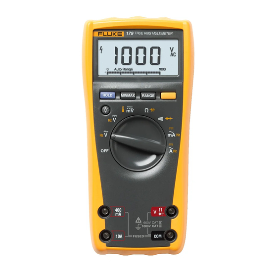
Models 175, 177 & 179 True RMS Multimeters "Warning" and "Caution" Statements The Fluke Model 175, Model 177, and Model 179 are battery- powered, true-RMS multimeters (hereafter "the Meter") with a A "XW Warning" identifies hazardous conditions and actions 6000-count, 3 3/4-digit display and a bar graph. This manual that could cause bodily harm or death. -
Page 6: Battery Saver ("Sleep Mode")
Models 175, 177 & 179 Users Manual Battery Saver ("Sleep Mode") Rotary Switch Positions The Meter enters the "Sleep mode" and blanks the display if there Switch Measurement Function is no function change or button press for 20 minutes. To disable Position the Sleep mode, hold down the YELLOW button while turning the AC voltage from 30.0 mV to 1000 V. -
Page 7: Display
True RMS Multimeters Display Display Symbol Meaning Measurement units. n F, F, C mVA, Mke, kHz Direct current, alternating current. DC, AC Low battery. Replace battery. All possible ranges. 610000mV Bar graph Analog display. Auto Range The Meter selects the range with the best resolution. -
Page 8: Min Max Avg Recording Mode
Models 175, 177 & 179 Users Manual MIN MAX AVG Recording Mode Display HOLD and AutoHOLD Modes The MIN MAX AVG recording mode captures the minimum and XW Warning maximum input values, and calculates a running average of all To avoid electric shock, do not use the Display HOLD or readings. -
Page 9: Manual Ranging And Autoranging
True RMS Multimeters Manual Ranging and Autoranging Manual Ranging and Autoranging Power-Up Options The Meter has both Manual range and Autorange modes. To select a Power-Up Option, hold down the button indicated while turning the Meter from OFF to any switch position. ⇒... -
Page 10: Making Basic Measurements
Models 175, 177 & 179 Users Manual Making Basic Measurements Measuring Resistance The figures on the following pages show how to make basic measurements. When connecting the test leads to the circuit or device, connect the common (COM) test lead before connecting the live lead; when removing the test leads, remove the live lead before HOLD MIN MAX... -
Page 11: Testing For Continuity
True RMS Multimeters Making Basic Measurements Testing for Continuity Testing Diodes Good Diode Good Diode HOLD MIN MAX RANGE HOLD MIN MAX RANGE HOLD MIN MAX RANGE HOLD MIN MAX RANGE Single Beep AIK06F.EPS Reverse Bias Forward Bias Measuring Temperature (Model 179 Only) Bad Diode Bad Diode HOLD... -
Page 12: Measuring Ac Or Dc Current
Models 175, 177 & 179 Users Manual Measuring AC or DC Current Understanding AC Zero Input Behavior of True RMS Meters Unlike averaging meters, which can accurately measure only pure XW Warning sinewaves, True RMS meters accurately measure distorted To avoid personal injury or damage to the Meter: waveforms. -
Page 13: Measuring Frequency
True RMS Multimeters Using the Bar Graph Measuring Frequency Using the Bar Graph XW Warning The bar graph is like the needle on an analog Meter. It has an overload indicator (>) to the right and a polarity indicator ( ) to the To avoid electrical shock, disregard the bar graph for left. -
Page 14: Cleaning
<12 <.5 HOLD MIN MAX RANGE AIK12F.EPS AIK13F.EPS F1 Fuse, 440 mA, 1000 V, FAST Fluke PN 943121 F2 Fuse, 11 A, 1000 V, FAST Fluke PN 803293 B1 Battery, 9 V Alkaline Fluke PN 614487 NEDA 1604 / 1604A... -
Page 15: Specifications
True RMS Multimeters Specifications Specifications Accuracy is specified for 1 yr after calibration, at operating temperatures of 18 C to 28 C, with relative humidity at 0 % to 90 %. Accuracy specifications take the form of: ( [ % of Reading ] + [ Counts ] ) Maximum voltage between any terminal and earth ground: 1000 V DC or AC RMS Surge Protection: 8 kV peak per IEC 61010... - Page 16 Models 175, 177 & 179 Users Manual Accuracy ±( [ % of Reading ] + [ Counts ] ) Function Range Resolution Model 175 Model 177 Model 179 600.0 mV 0.1 mV 1.0 % + 3 1.0 % + 3 1.0 % + 3 2, 3 AC Volts...
- Page 17 True RMS Multimeters Specifications Accuracy ±( [ % of Reading ] + [ Counts ] ) Function Range Resolution Model 175 Model 177 Model 179 60.00 mA 0.01 mA DC Amps 400.0 mA 0.1 mA 1.0 % + 3 1.0 % + 3 1.0 % + 3 6.000 A 0.001 A...
- Page 18 Models 175, 177 & 179 Users Manual Common Mode Rejection Ratio Input Impedance Function Overload Protection Normal Mode Rejection (Nominal) (1 k Unbalanced) Volts AC 1000 V RMS > 10 M < 100 pF > 60 dB @ DC, 50 Hz or 60 Hz Volts DC 1000 V RMS >...