Fluke 15B Calibration Manual
Hide thumbs
Also See for 15B:
- User manual (28 pages) ,
- Calibration manual (23 pages) ,
- User manual (20 pages)

Related Manuals for Fluke 15B


Summary of Contents for Fluke 15B
- Page 1 ® 15B & 17B Digital Multimeters Calibration Manual PN 2061398 May 2003 © 2003 Fluke Corporation, All rights reserved. Printed in USA All product names are trademarks of their respective companies.
- Page 2 LIMITED WARRANTY AND LIMITATION OF LIABILITY This Fluke product will be free from defects in material and workmanship for one year from the date of purchase. This warranty does not cover fuses, disposable batteries, or damage from accident, neglect, misuse, alteration, contamination, or abnormal conditions of operation or handling.
-
Page 3: Table Of Contents
Performance Tests ..................... 7 Preparing for the Performance Test............... 7 Testing the Display..................8 Performance Test Procedures................ 8 Meter Adjustment ....................15 15B Adjustment..................... 16 17B Adjustment..................... 18 Maintenance....................... 20 General Maintenance..................21 Testing the Fuses ................... 21 Replacing the Batteries and Fuses..............21... - Page 4 15B & 17B Calibration Manual...
- Page 5 List of Tables Table Title Page International Electrical Symbols ................3 Required Equipment....................7 15B Performance Test.................... 9 17B Performance Test.................... 11 15B Adjustment ..................... 16 17B Adjustment ..................... 18 Replacement Parts....................22...
- Page 6 15B & 17B Calibration Manual...
- Page 7 List of Figures Figure Title Page Display ........................8 Temperature Performance Test Connections............14 15B Adjustment Points ..................17 17B Adjustment Points ..................19 Temperature Adjustment Connections..............20 Replacing the Batteries and Fuses ................. 22...
- Page 8 15B & 17B Calibration Manual...
-
Page 9: Introduction
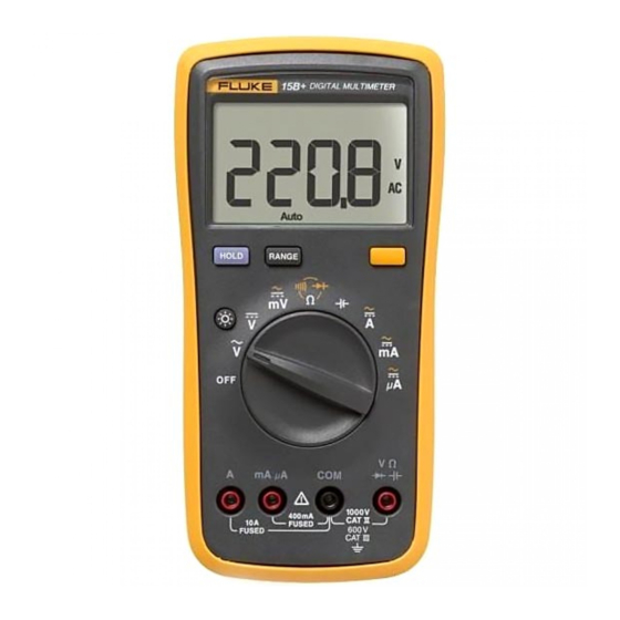
• Read “Safety Information” before using this Meter. The Fluke 15B and 17B Multimeters (hereafter referred to as “the Meter”) are battery operated, 4,000 count instruments, with a digital display. Except where noted, the descriptions and instructions in this manual apply to both models of the Meter. -
Page 10: Safety Information
15B & 17B Calibration Manual Safety Information The Meters comply with IEC 1010-1 CAT I 1000 V, CAT II 600 V, and CAT III 300 V overvoltage standards. Refer to “Specifications” for more information. In this manual, a Warning identifies conditions and actions that pose hazards to the user. -
Page 11: International Electrical Symbols
Digital Multimeter Safety Information • For all dc functions, including manual or auto-ranging, to avoid the risk of shock due to possible improper reading, verify the presence of any ac voltages by first using the ac function. Then select a dc voltage range equal to or greater than the ac range. -
Page 12: General Specifications
15B & 17B Calibration Manual General Specifications Maximum Voltage between any Terminal and Earth Ground: 1000 V W Fuse Protection for mA µA inputs: 500 mA, 1000 V FAST, Min. Interrupt Rating 20,000 A W Fuse Protection for A input: 10 A, 1000 V FAST, Min. -
Page 13: Accuracy Specifications
Accuracy specifications take the form of: ±([% of Reading] + [Number of Least Significant Digits]) Accuracy Function Range Resolution Model 15B Model 17B 400.0 mV 0.1 mV 3.0 % + 3 3.0 % + 3 AC Volts (40 to 500 Hz) 4.000 V... - Page 14 15B & 17B Calibration Manual Accuracy Function Range Resolution Model 15B Model 17B 400.0 µA 0.1 µA AC Current (40 to 200 Hz) 1.5 % + 3 1.5 % + 3 4000 µA 1 µA AC Current (40 to 200 Hz) 40.00 mA...
-
Page 15: Performance Tests
Table 2. Required Equipment Equipment Recommended Model AC Calibrator Fluke 5520A Digital Thermometer Fluke 50S with 80Pk-3A Surface Probe Thermocouple Adapter 80AK K-Type Thermocouple Adapter 3 Volt Lab Power Supply Thermocouple K-Type with male mini connectors at each end. Preparing for the Performance Test... -
Page 16: Testing The Display
If the UUT fails to perform within the low-high range indicated for each test in Table 3 or Table 4, adjust the Meter and go through the performance test procedure again. If the UUT still fails to perform within the ranges indicated, then repair is necessary. Refer to “Contacting Fluke” to locate a service center. - Page 17 Digital Multimeter Performance Tests Table 3. 15B Performance Test Test Switch 5520A UUT Reading Step Push Button Function Position Output Limits Volts AC 3.5 V 50 Hz 3.462 to 3.538 V ac 35 V 500 Hz 34.62 to 35.38 V ac 350 V 50 Hz 346.2 to 353.8 V ac...
- Page 18 UUT Reading Step Push Button Function Position Output Limits For the 15B Capacitance Test, subtract the test lead capacitance from the UUT reading to get measurement result. Capacitance 48 nF 46.99 to 49.01 nF 0.48 µF 469.9 to 490.1 µF 4.8 µF...
-
Page 19: Performance Test
Digital Multimeter Performance Tests Table 4. 17B Performance Test Test UUT Switch UUT Push Step 5520A Output UUT Display limits Function Setting Button Volts AC 3.5 V 50 Hz 3.462 to 3.538 V ac 35 V 500 Hz 34.62 to 35.38 V ac 350 V 50 Hz 346.2 to 353.8 V ac 1000 V 50 Hz... - Page 20 15B & 17B Calibration Manual Table 4. 17B Performance Test (cont.) Test UUT Switch UUT Push Step 5520A Output UUT Display limits Function Setting Button Volts DC 3.5 V dc 3.480 to 3.520 V dc 35 V dc 34.80 to 35.20 V dc 350 V dc 348.0 to 352.0 V dc...
- Page 21 Digital Multimeter Performance Tests Table 4. 17B Performance Test (cont.) Test UUT Switch UUT Push Step 5520A Output UUT Display limits Function Setting Button For step 35, wait 15 seconds for the reading to settle. 95 µF t icon ON Capacitance 89.7 to 100.3 µF Amps DC...
- Page 22 15B & 17B Calibration Manual mA A 400mA FUSED CAT II 600 V FUSED aes7f.eps Figure 2. Temperature Performance Test Connections...
-
Page 23: Meter Adjustment
8. Replace the yellow holster. 9. Verify the meter adjustment by going through the performance test procedures. If the Meter still does not meet the performance test specifications, service is required. Refer to “Contacting Fluke” to locate a service center. -
Page 24: 15B Adjustment
15B & 17B Calibration Manual 15B Adjustment Refer to Table 5 for the 15B adjustment procedure and Figure 3 for the adjustment points. Table 5. 15B Adjustment Test Step Switch Button Potentiometer 5520 UUT Test Specifications Function mV dc 350 mV dc 349.9 to 350.1 mV dc... - Page 25 Digital Multimeter Meter Adjustment Adjustment Points aes2f.eps Figure 3. 15B Adjustment Points...
-
Page 26: Adjustment
15B & 17B Calibration Manual 17B Adjustment Refer to Table 6 for the 17B adjustment procedure, Figure 4 for the adjustment points, and Figure 5 for temperature adjustment connections. Table 6. 17B Adjustment Test Step Switch Button Potentiometer 5520 UUT Test Specifications... - Page 27 Digital Multimeter Meter Adjustment Adjustment Points aes1f.eps Figure 4. 17B Adjustment Points...
-
Page 28: Maintenance
15B & 17B Calibration Manual aes4f.eps Figure 5. Temperature Adjustment Connections Maintenance WXWarning Beyond replacing batteries and fuses, do not attempt to repair or service your Meter unless you are qualified to do so and have the relevant calibration, performance test, and service... -
Page 29: General Maintenance
0.990 kΩ and 1.010 kΩ. 3. If the display reads o, replace the fuse and test again. 4. If the display shows any other value, have the Meter serviced. Refer to “Contacting Fluke”. Replacing the Batteries and Fuses XW Warning... -
Page 30: Customer Replaceable Parts
W F2 Fuse, 10 A, 1000 V 1989726 Min. Interrupt Rating 20,000 A B1 Battery, 2 X AA Alkaline 376756 NEDA 15A, IEC LR6 Battery Door 1884065 TL71 Precision Probe Assembly (not shown) 1274382 15B & 17B Users Manual (not shown) 1991246...