Fluke 175 User Manual
Hide thumbs
Also See for 175:
- User manual ,
- Calibration information manual (23 pages) ,
- Supplement manual (3 pages)
Table of Contents

Related Manuals for Fluke 175


Summary of Contents for Fluke 175
- Page 1 175, 177, 179 True-rms Multimeters Users Manual May 2003 Rev. 2, 10/15 © 2003-2015 Fluke Corporation. All rights reserved. Specifications are subject to change without notice. All product names are trademarks of their respective companies.
- Page 2 Lifetime Limited Warranty Each Fluke 20, 70, 80, 170 and 180 Series DMM will be free from defects in material and workmanship for its lifetime. As used herein, “life- time” is defined as seven years after Fluke discontinues manufacturing the product, but the warranty period shall be at least ten years from the date of purchase.
-
Page 3: Table Of Contents
Table of Contents Title Page Introduction ..........................1 How to Contact Fluke ......................1 Safety Information ........................1 Symbols ........................... 3 Unsafe Voltage ........................5 Test Lead Alert ........................5 Terminals ..........................5 Product Buttons ........................6 Rotary Switch Positions ......................6 Display ............................. - Page 4 175, 177, 179 Users Manual Maintenance ..........................16 Clean the Product ....................... 17 Test the Fuses ........................17 Replace the Battery and Fuses ..................17 Specifications ........................... 18 Electrical Specifications ......................20...
-
Page 5: Introduction
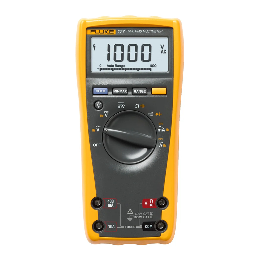
Or, visit Fluke's website at www.fluke.com. To register your product, visit http://register.fluke.com. The Fluke 175, 177, and 179 are battery-powered, True-rms multimeters (the Product) with a 6000-count, 3 3/4-digit display To view, print, or download the latest manual supplement, visit and a bar graph. - Page 6 175, 177, 179 Users Manual • • Examine the case before you use the Product. Look Do not touch voltages >30 V ac rms, 42 V ac peak, or for cracks or missing plastic. Carefully look at the 60 V dc.
-
Page 7: Symbols
True-rms Multimeters Symbols • • The battery door must be closed and locked before Do not use test leads if they are damaged. Examine you operate the Product. the test leads for damaged insulation and measure a known voltage. • Use only cables with correct voltage ratings. - Page 8 175, 177, 179 Users Manual Table 1. Symbols (cont.) Table 1. Symbols (cont.) Symbol Description Symbol Description Earth Measurement Category II is applicable to test and measuring circuits connected directly to utilization Capacitance points (socket outlets and similar points) of the low-voltage MAINS installation.
-
Page 9: Unsafe Voltage
True-rms Multimeters Unsafe Voltage Unsafe Voltage Table 2. Terminals During a voltage measurement, the Product alerts you to the presence of a potentially hazardous voltage. When the Product detects a voltage ≥30 V or a voltage overload (), the symbol shows on the display to alert you to the presence of a potentially hazardous voltage. -
Page 10: Product Buttons
175, 177, 179 Users Manual Product Buttons Table 3. Product Buttons Item Description Table 3 identifies the basic functions of the buttons on the Product. The buttons have other functions described later in the manual. Activates MIN MAX AVG mode. -
Page 11: Display
True-rms Multimeters Display Display Table 4. Rotary Switch Positions Switch Table 5 shows the items on the Product display. Measurement Function Position Table 5. Display DC mV 0.1 mV to 600 mV. Temperature −40 °C to +400 °C. −40 °F to +752 °F. - Page 12 175, 177, 179 Users Manual Table 5. Display (cont.) Table 5. Display (cont.) Item Symbol Description Item Symbol Description Display HOLD is enabled. Display The Product selects the range with Auto Range freezes present reading. the best resolution. ...
-
Page 13: Battery Saver (Sleep Mode)
True-rms Multimeters Battery Saver (Sleep Mode) Battery Saver (Sleep Mode) To use MIN MAX AVG recording: 1. Set the desired measurement function and range. The Product enters the Sleep mode and the display goes blank if (Autoranging is disabled in the MIN MAX AVG mode.) there is no function change or button press for 20 minutes. -
Page 14: Display Hold And Autohold Modes
175, 177, 179 Users Manual Display HOLD and AutoHOLD Modes Manual Range and Autorange XW Warning The Product has both Manual range and Autorange modes. To avoid electric shock, fire, or personal injury, do not • In the Autorange mode, the Product selects the range with the best resolution. -
Page 15: Power-Up Options
True-rms Multimeters Power-Up Options 3. To exit Manual Range, press for 1 second or turn the Table 7. Power-Up Options rotary switch. Button Power-Up Options The Product returns to Autorange and Auto Range shows. switch position turns on all LCD segments. AutoHOLD Power-Up Options ... -
Page 16: Measure Ac And Dc Voltage
175, 177, 179 Users Manual XW Warning Measure Resistance To avoid electric shock, fire, or personal injury: • Connect the common test lead before the live test lead and remove the live test lead before the common test lead. MIN MAX... -
Page 17: Test For Continuity
True-rms Multimeters Basic Measurements Test Diodes Test for Continuity Good Diode Good Diode HOLD MIN MAX RANGE HOLD MIN MAX RANGE HOLD MIN MAX RANGE HOLD MIN MAX RANGE Single Beep AIK06F.EPS Forward Bias Reverse Bias Measure Temperature (179 Only) Bad Diode Bad Diode HOLD... -
Page 18: Measure Ac Or Dc Current
175, 177, 179 Users Manual Measure AC or DC Current XW Warning To prevent possible electrical shock, fire, or personal HOLD MIN MAX RANGE injury: • Never attempt to make an in-circuit current measurement when the open-circuit potential to earth is >1000 V. -
Page 19: Measure Frequency
True-rms Multimeters Basic Measurements Measure Frequency AC Current Frequency XW Warning To prevent possible electrical shock, fire, or personal injury, disregard the bar graph for frequencies >1 kHz. If the frequency of the measured signal is >1 kHz, the bar HOLD MIN MAX RANGE... -
Page 20: Use The Bar Graph
175, 177, 179 Users Manual Use the Bar Graph Maintenance The bar graph is like the needle on an analog meter. It has an XW Warning overload indicator () to the right and a polarity indicator (±) to the To prevent possible electrical shock, fire, personal left. -
Page 21: Clean The Product
True-rms Multimeters Maintenance Clean the Product Replace the Battery and Fuses Wipe the case with a damp cloth and mild detergent. Do not use XW Warning abrasives or solvents. Dirt or moisture in the terminals can affect To prevent possible electrical shock, fire, personal readings. -
Page 22: Specifications
175, 177, 179 Users Manual Specifications Table 8. Replacement Battery and Fuses Accuracy is specified for 1 yr after calibration, at operating temperatures of 18 °C to 28 °C, with relative humidity at 0 % to 90 %. Accuracy specifications take the form of: ±([% of Reading] +... - Page 23 True-rms Multimeters Specifications Relative Humidity ......Maximum Non-condensing: Class A: Equipment is suitable for use in all establishments other than 90 % to 35 °C, domestic and those directly connected to a low-voltage power supply 75 % to 40 °C, network that supplies buildings used for domestic purposes. There 45 % to 50 °C may be potential difficulties in ensuring electromagnetic compatibility in other environments due to conducted and radiated disturbances.
-
Page 24: Electrical Specifications
175, 177, 179 Users Manual Electrical Specifications Accuracy ±( [ % of Reading ] + [ Counts ] ) Function Range Resolution 600.0 mV 0.1 mV 1.0 % + 3 1.0 % + 3 1.0 % + 3 (45 Hz to 500 Hz) - Page 25 True-rms Multimeters Electrical Specifications Accuracy ±( [ % of Reading ] + [ Counts ] ) Function Range Resolution Diode test 2.400 V 0.001 V 1 % + 2 1000 nF 1 nF 1.2 % + 2 1.2 % + 2 1.2 % + 2 10.00 μF 0.01 μF...
- Page 26 175, 177, 179 Users Manual Accuracy ±( [ % of Reading ] + [ Counts ] ) Function Range Resolution [11] -40 °C to +400 °C 0.1 °C 1 % + 10 [10] Temperature [10] -40 °F to +752 °F 0.1 °F...
- Page 27 True-rms Multimeters Electrical Specifications Input Impedance Common Mode Rejection Ratio Function Overload Protection Normal Mode Rejection (Nominal) (1 kΩ Unbalanced) Volts ac 1000 V rms >10 MΩ < 100 pF >60 dB @ dc, 50 Hz or 60 Hz Volts dc 1000 V rms >10 MΩ...
- Page 28 175, 177, 179 Users Manual Frequency Counter Sensitivity Typical Sensitivity (RMS Sine Wave) [1] [2] Input Range 2 Hz to 45 Hz 45 Hz to 10 kHz 10 kHz to 20 kHz 20 kHz to 50 kHz 50 kHz to 100 kHz...