Bushnell Tour V2 - Laser Rangefinder Manual
- Owner's manual (96 pages) ,
- User manual (44 pages) ,
- Manual (96 pages)
Advertisement
- 1 OVERVIEW
- 2 INTRODUCTION
- 3 HOW OUR DIGITAL TECHNOLOGY WORKS
- 4 RANGING ACCURACY
- 5 GETTING STARTED
- 6 ADJUSTING THE EYEPIECE
- 7 OPERATIONAL SUMMARY
- 8 LIQUID CRYSTAL DISPLAY (LCD) INDICATORS
- 9 UNIT OF MEASURE OPTIONS
- 10 ACTIVE LASER
- 11 SELECTIVE TARGETING MODES
- 12 OPTICAL DESIGN
- 13 TRIPOD MOUNT
- 14 SPECIFICATIONS
- 15 CLEANING
- 16 TROUBLE SHOOTING TABLE
- 17 TWO-YEAR LIMITED WARRANTY
- 18 Documents / Resources
OVERVIEW

INTRODUCTION
The TOUR V2 is a precision Laser Rangefinding optical instrument designed to provide many years of enjoyment. This booklet will help you achieve optimum performance by explaining its adjustments and features as well as how to care for this precise laser rangefinding optical instrument. To ensure optimal performance and longevity, please read these instructions before using your TOUR V2.
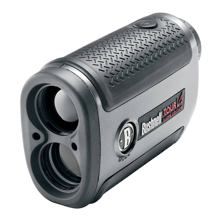
Your Tour V2 is Bushnell's newest addition to an award winning line of golf laser rangefinders specifically made for golfers. Tour V2 features PinSeeker™ technology, allowing the golfer to easily and quickly "zero" in on the flag without acquiring background targets. The Tour V2 is the most compact laser rangefinder on the market, weighing a mere 6.6 ounces and made to fit into the palm of your hand. Tour V2 also features and adjustable eyepiece, 5X magnification, and is capable of providing distance from 5 to 1000 yards with incredible one yard accuracy! Like other Bushnell laser rangefinders, the Tour V2 is not dependent upon reflectors, and will provide distance to trees, bunkers, and virtually any object on the course, to any golf course in the world.
HOW OUR DIGITAL TECHNOLOGY WORKS
The TOUR V2 WITH PINSEEKER emits invisible, eye safe, infrared energy pulses. The TOUR V2 WITH PINSEEKER's Advanced Digital microprocessor and ASIC chip (Application-Specific Integrated Circuit) results in instantaneous and accurate readings every time. Sophisticated digital technology instantaneously calculates distances by measuring the time it takes for each pulse to travel from the rangefinder, to the target, and back.
RANGING ACCURACY
The ranging accuracy of the TOUR V2 is plus or minus one yard/meter under most circumstances. The maximum range of the instrument depends on the reflectivity of the target. The maximum distance for most objects is 700 yards/640 meters while for highly reflective objects the maximum is 1000 yards/914 meters. Note: You will get both longer and shorter maximum distances depending on the reflective properties of the particular target and the environmental conditions at the time the distance of an object is being measured.
The color, surface finish, size and shape of the target all affect reflectivity and range. The brighter the color, the longer the range. Red is highly reflective, for example, and allows longer ranges than the color black, which is the least reflective color. A shiny finish provides more range than a dull one. A small target is more difficult to range than a larger target. The angle to the target also has an effect. Shooting to a target at a 90 degree angle (where the target surface is perpendicular to the flight path of the emitted energy pulses) provides good range while a steep angle on the other hand, provides limited ranging. In addition, lighting conditions (e.g. the amount of sunlight) will affect the ranging capabilities of the unit. The less light (e.g. overcast skies) the farther the unit's maximum range will be. Conversely, very sunny days will decrease the unit's maximum range.
GETTING STARTED
INSERTING THE BATTERY
Remove the battery cap by lifting the battery door tab and then rotating counter clockwise. Insert a CR-2 3-volt lithium battery into the compartment positive end first, then replace the battery cap.
NOTE: It is recommended that the battery be replaced at least once every 12 months.
Low Battery Indicator: If the  is displayed within the in-view readout, this means "low battery" or battery charge is getting low and the 3-volt lithium battery should be replaced.

ADJUSTING THE EYEPIECE
Your TOUR V2 is constructed with an adjustable eyepiece (+/- 2 Diopter Adjustment) that allows one to focus the LCD display relative to the image. Simply rotate the eyepiece until the reticle and object distanced to are in focus to your eye.
OPERATIONAL SUMMARY
While looking through the 5x eyepiece, depress the power button once to activate the in-view Liquid Crystal Display (LCD). Place the aiming circle (located in the center of the field of view) upon a target at least 5 yards away, depress and hold the power button down until the range reading is displayed near the bottom of the in-view display. Crosshairs surrounding the aiming circle indicate that the laser is being transmitted. Once a range has been acquired, you can release the power button. The crosshairs surrounding the aiming circle will disappear once the power button has been released (i.e. the laser is no longer being transmitted). Note: Once activated, the LCD will remain active and display the last distance measurement for 30 seconds. You can depress the power button again at any time to distance to a new target. As with any laser device, it is not recommended to directly view the emissions for long periods of time with magnified lenses. The maximum time the laser is transmitted (fired) is 10 seconds. To re-fire, press the button down again.
LIQUID CRYSTAL DISPLAY (LCD) INDICATORS
Your TOUR V2 WITH PINSEEKER's LCD incorporates illuminated indicators that advise the user unit of measure, when the laser is actively firing, when a target has been acquired, and targeting modes. A summary of these features is presented below:
UNIT OF MEASURE OPTIONS
The TOUR V2 can be used to measure distances in yards or meters. The unit of measure indicators are located in the lower right portion of the LCD. To select between yards and meters, quickly press and release the POWER button to turn on the unit (on top of the unit), look through the eyepiece, depress the "MODE" button (left side of the eyepiece) and hold it down for approximately 5 seconds. If you are changing from yards to meters, a change in unit of measure will be indicated by the illumination of the M for meter indicator while the Y for Yard indicator is turned off. If you are changing from meters to yards, the opposite will occur. The TOUR V2 will return to the last unit of measure setting used each time the unit is turned on.
ACTIVE LASER
Crosshairs surrounding the aiming circle indicate that the laser is being transmitted. Once a range has been acquired, you can release the power button. The crosshairs surrounding the circle will disappear once the power button has been released (i.e. the laser is no longer being transmitted).
SELECTIVE TARGETING™ MODES
The TOUR V2 WITH PINSEEKER was especially designed with golfers in mind. The selective targeting modes allow you to adjust the performance parameters of the unit to suit your specific situation and environment. To move from one mode to another, press the POWER button once to turn on the unit. While looking through the eyepiece, press the MODE button and quickly release. The different targeting modes available and mode indicators are listed below:
PinSeeker (LCD Indicator - ![]() ) Ever have trouble getting distance to the flag? This advanced mode allows easy acquisition of the flag without inadvertently getting distances to background targets (i.e. trees) that have stronger signal strength.
) Ever have trouble getting distance to the flag? This advanced mode allows easy acquisition of the flag without inadvertently getting distances to background targets (i.e. trees) that have stronger signal strength.
Once in this mode, press the POWER button to turn the unit on. Next, align the aiming circle reticle onto the flag that you want distance to. Next, press and hold the POWER button and move the laser slowly over the flag or desired object until a circle surrounds the flag indicator. If the laser beam recognized more than one object (i.e. flag and background trees), distance of the flag will be displayed and a circle will surround the PinSeeker indicator informing the user that distance to the flag (i.e. closer object) is being displayed in the LCD (as seen below). There may be times when only the laser beam only sees one object in its path. In this case, the distance will be displayed, but because more than one object was not acquired, a circle will not surround the flag indicator.
TIP: While pressing the POWER button, you can move the device slowly from object to object and intentionally force the laser to hit multiple objects to ensure that you are only displaying the closest of the objects recognized by the laser. Once the device has shut off, the unit will always default back to the last mode used.

Tour V2 - Slope Edition (LCD Indicator - ° ![]() ) This advanced and patented mode found on SLOPE EDITION models features a built-in accelerometer-based inclinometer that digitally displays the exact slope angle from -20 to +20 degrees of elevation and is +/- 1.0 degree accurate. The Slope +/-™ mode will automatically compute an angle compensated range based upon distance and slope angle determined by the laser rangefinder and built-in inclinometer. This data is then combined with internal algorithmic formulas dealing with average club use and ball trajectories. The angle compensated range provides direction on how to play the shot (i.e. add distance if an incline, subtract distance if a decline).
) This advanced and patented mode found on SLOPE EDITION models features a built-in accelerometer-based inclinometer that digitally displays the exact slope angle from -20 to +20 degrees of elevation and is +/- 1.0 degree accurate. The Slope +/-™ mode will automatically compute an angle compensated range based upon distance and slope angle determined by the laser rangefinder and built-in inclinometer. This data is then combined with internal algorithmic formulas dealing with average club use and ball trajectories. The angle compensated range provides direction on how to play the shot (i.e. add distance if an incline, subtract distance if a decline).

How to use Slope™ Mode
Once in this mode, you will see a " °  " in the field of view informing you that you are in the Slope +/- Mode. Press the POWER button to obtain distance to the flag or other objects. Once the range is displayed, continue to hold the POWER button down for approximately 2 seconds while holding the aiming circle on the flag and keeping the unit as steady as possible so as to allow the inclinometer enough time to measure slope. Then release the POWER button. Once you have released the power button, a degree of angle and compensated range will be displayed beneath the standard distance as seen below.
In this example, the true distance is 162 yards, slope is +4 degrees, and the compensated range is 173 yards. The " ![]() " symbol means "Play-As", so instead of playing as 162 yards, "play-as" 173 yards.
" symbol means "Play-As", so instead of playing as 162 yards, "play-as" 173 yards.

The Advantage of Slope Edition
The distance to flag A in the drawing below is 162 yards.
It is also 162 yards to flag B although it is on a slope. However, if you were to play this hole as 162 yards, the ball (X) would fall short of the hole/flag because you did nottake slope into account.

The Truth about Slopes
Trying to determine slope angle with the naked eye can be rather deceiving. Most are not well versed to accurately determine slope angle. For example, most golf courses average slope is approximately 4 degrees. A large slope at a golf course is generally no more than 8 degrees. Of course this can vary, and that is why this device will measure slope from -20 to 20 degrees.
Some real world examples may help clarify. A moderate roof pitch is 6/12, which means that the roof rises six inches for every 12 inch horizontal distance. That equates to 26.5 degrees. You can scramble up this pitch when hanging Christmas lights, but climbing that slope for the distance of a good golf shot on a course would be exhausting. To retrieve a 200 yards shot, you would climb 300 feet up!
Golf Example: Let's say you are a strong golfer with a 300 yard shot. At a 20 degree slope the Pin would be 50 feet above you. In other words, you be driving the ball to the top of a 5 story building!!!
NOTE: For your convenience, the Slope Edition also contains the PinSeeker® Mode/feature. If at any time you prefer not to use the Slope Mode, simply press the MODE button to get to PinSeeker® or Standard with Automatic SCAN Mode.™
Standard with Automatic SCAN: This setting allows most targets to be distanced up to 1000 yards. Used for moderately reflective targets that are typical of most distancing situations. The minimum distance in the standard mode is 5 yards. To use the Automatic SCAN feature, simply hold down on the POWER button for approximately 3 seconds and SCAN the rangefinder from object to object while leaving the POWER button depressed. Automatic SCAN will allow the range and display to be continuously updated very rapidly as multiple objects are targeted.
OPTICAL DESIGN
Magnification and Coatings
The TOUR V2 features 5x magnification and Multi-Coated optics. A liquid crystal display (LCD) is mounted within the optical system and when activated, displays a reticle for targeting, yards/meters, and Mode indicators. Inherent in the manufacturing process are small black spots that appear in the optical system. These are a natural characteristic of the LCD and cannot be fully eliminated in the manufacturing process. They do not affect the distancing performance of the unit.
TRIPOD MOUNT
Molded into the bottom of your TOUR V2 is a threaded tripod mount that will allow you to attach a tripod for a more stable operation during long periods of use.
SPECIFICATIONS
| Dimensions: Measuring 4.3 x 2.8 x 1.6 inches | Display: LCD |
| Weight: 6.6 oz. | Power Source: 3-volt lithium (included) |
| Ranging Accuracy: +/- 1 yard | Field Of View: 367 ft. @ 1000 yards |
| Range: 5-1000 Yards / 5-914 Meters | Extra Long Eye Relief: 21mm |
| Magnification: 5x | Exit Pupil: 4.8 mm |
| Objective Diameter: 24 mm | Built-In Tripod Mount |
| Optical Coatings: Multi-Coated | Includes battery and carrying case |
Patent #'s: 6,445,444 | 5,612,779 | 6,057,910 | 6,226,077 | 7,239,377 (Slope Edition) | 7,535,553 (Slope Edition) | 7,859,650
CLEANING
Gently blow away any dust or debris on the lenses (or use a soft lens brush). To remove dirt or fingerprints, clean with a soft cotton cloth, rubbing in a circular motion. Use of a coarse cloth or unnecessary rubbing may scratch the lens surface and eventually cause permanent damage. For a more thorough cleaning, photographic lens tissue and photographic-type lens cleaning fluid or isopropyl alcohol may be used. Always apply the fluid to the cleaning cloth – never directly on the lens.
TROUBLE SHOOTING TABLE
If unit does not turn on - LCD does not illuminate:
- Depress POWER button.
- Check and if necessary, replace battery. If unit does not respond to key presses, replace the battery with a good quality 3 volt lithium battery.
If unit powers down (display goes blank when attempting to power the laser):
- The battery is either weak or low quality. Replace the battery with a good quality 3-volt lithium battery.
If target range cannot be obtained
- Make sure LCD is illuminated.
- Make sure that the power button is being depressed.
- Make sure that nothing, such as your hand or finger, is blocking the objective lenses (lenses closest to the target) that emit and receive the laser pulses.
- Make sure unit is held steady while depressing power button.
NOTE: The last range reading does not need to be cleared before ranging another target. Simply aim at the new target using the LCD's reticle, depress the power button and hold until new range reading is displayed. Specifications, instructions, and the operation of these products are subject to change without notice.
TWO-YEAR LIMITED WARRANTY
Your Bushnell product is warranted to be free of defects in materials and workmanship for two years after the date of purchase. In the event of a defect under this warranty, we will, at our option, repair or replace the product, provided that you return the product postage prepaid. This warranty does not cover damages caused by misuse, improper handling, installation, or maintenance provided by someone other than a Bushnell Authorized service Department.
Any return made under this warranty must be accompanied by the items listed below:
- A check/money order in the amount of $10.00 to cover the cost of postage and handling
- Name and address for product return
- An explanation of the defect
- Proof of Date Purchased
- Product should be well packed in a sturdy outside shipping carton, to prevent damage in transit, with return postage prepaid to the address listed below:
IN U.S.A. Send To:
Bushnell Outdoor Products
Attn.: Repairs 9200
Cody Overland Park, Kansas 66214
IN CANADA Send To:
Bushnell Outdoor Products
Attn.: Repairs 25A East
Pearce street, Unit 1 Richmond Hill,
Ontario l4B 2M9
For products purchased outside the United states or Canada please contact your local dealer for applicable warranty information.
In europe you may also contact Bushnell at:
Bushnell Germany GmbH
European service Centre
Mathias-Brüggen-str. 80
D-50827 Köln
GERMANY
Tel: +49 221 995568-0
Fax: +49 221 995568-20
This warranty gives you specific legal rights.
You may have other rights which vary from country to country.
©2011 Bushnell Outdoor Products

Documents / ResourcesDownload manual
Here you can download full pdf version of manual, it may contain additional safety instructions, warranty information, FCC rules, etc.
Advertisement
Thank you! Your question has been received!


Need Assistance?
Do you have a question about the Tour V2 that isn't answered in the manual? Leave your question here.