Table of Contents
Advertisement
Quick Links
Advertisement
Table of Contents

Related Manuals for MSI S2205 2U24


Summary of Contents for MSI S2205 2U24
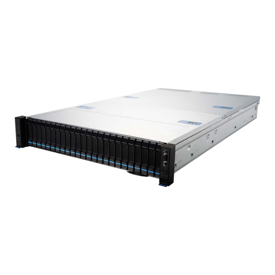
- Page 1 S2205 (2U24) MS-S322 Server System User Guide...
-
Page 2: Table Of Contents
Contents Regulatory Notices ....................... 4 Copyright and Trademarks Notice ................5 Technical Support......................5 Safety Information ......................6 System Specifications ....................7 System Overview ......................8 System LED Indicators ....................11 Motherboard Overview ....................12 Motherboard Connector .................... 13 Power Connector ....................13 Storage Connector .................... - Page 3 Memory ........................33 Recommended Memory Population ..............34 Installing Memory Modules .................. 36 M.2 M Key ........................37 Installing M.2 M Key ..................... 37 PCIe Add-in Card ......................38 Installing PCIe Add-in Card .................. 38 Installing Riser Card Assembly ................39 System Fan .........................
-
Page 4: Regulatory Notices
Chemical Substances Information In compliance with chemical substances regulations, such as the EU REACH Regulation (Regulation EC No. 1907/2006 of the European Parliament and the Council), MSI provides the information of chemical substances in products at: https://csr.msi.com/global/index CE Conformity Hereby, Micro-Star International CO., LTD declares that this device is in compliance with the essential safety requirements and other relevant provisions set out in the European Directive. -
Page 5: Copyright And Trademarks Notice
Copyright and Trademarks Notice Copyright © Micro-Star Int’l Co., Ltd. All rights reserved. The MSI logo used is a registered trademark of Micro-Star Int’l Co., Ltd. All other marks and names mentioned may be trademarks of their respective owners. No warranty as to accuracy or completeness is expressed or implied. -
Page 6: Safety Information
Safety Information ∙ Always read the safety instructions carefully. ∙ Keep this User’s Manual for future reference. ∙ Keep this equipment away from humidity. ∙ Lay this equipment on a reliable flat surface before setting it up. ∙ The openings on the enclosure are for air convection hence protects the equipment from overheating. -
Page 7: System Specifications
System Specifications Model S2205-04 Form Factor Dimensions 17.2”W (438mm) x 3.4”H (87mm) x 30.3”D (770mm) Processor ∙ 2 x Intel® Xeon® Processor Scalable Family (Socket-E) - Sapphire Rapids (SPR)/ Emerald Rapids (EMR) Chipset Intel® C741 Memory ∙ 32 x DDR5 RDIMM/ RDIMM-3DS, w/ ECC - SPR: 4800MTs (1DPC)/ 4400MTs (2DPC) - EMR: 5600MTs (1DPC)/ 4800MTs (2DPC) - 8 x Channels DDR5 per CPU/ 2DPC 16 DIMMs per socket... -
Page 8: System Overview
System Overview 16 x 2.5” NVMe 8 x 2.5” NVMe/ SATA Hot-Swap Drive Bays Hybrid Hot-Swap Drive Bays 4 x 2.5” SATA Hot-Swap Drive Bays Riser #1 Riser #1 Riser #2 Riser #2 (Optional) System Overview... - Page 9 USB 2.0 Port This connector is provided for USB peripheral devices. (Speed up to 480 Mbps) VGA Port System Power Button/ LED UID Button/ LED System Reset Button System Status LED NIC Link LEDs M.2 Activity LED UID LED Button (or BMC Reset Button, via jumper: J1_1) RJ45 Serial Console Port GbE RJ45 Port (Optional) The standard RJ45 LAN jack is provided for connection to the Local Area...
- Page 10 GbE RJ45 Port (for Mgmt.) The standard RJ45 LAN jack is provided for connection to the Local Area Network (LAN). You can connect a network cable to it. Status Description No link Link/ Activity Linked Green LINK/ACT SPEED Blinking Data activity 10 Mbps Speed LED 100 Mbps...
-
Page 11: System Led Indicators
System LED Indicators UID Button/ LED System Power Button/ LED System Reset Button M.2 Activity LED System Status LED NIC Link LED LED State Description Power LED System power is on Blue System power is on ACPI S0 state System is sleeping Blinking System power is off System power is on ACPI S4, S5 state... -
Page 12: Motherboard Overview
Motherboard Overview BAT1 OCP1 JPWR1 JPWR2 CPU1 CPU0 Motherboard Overview... -
Page 13: Motherboard Connector
Motherboard Connector Power Connector JPWR2 JPWR1 JPWR3 JPWR10 JPWR7 JPWR6 JPWR4 JPWR5 JPWR11 JPWR8 JPWR9 JPWR1, JPWR2: CRPS Power Connector These CRPS (Common Redundant Power Supplies) connectors allow you to connect a power supply. To connect the power supply, ensure that the plug is inserted in the proper orientation and that the pins are aligned. - Page 14 JPWR7: Rear Side BP Power Connector This connector provides power output to HDDs on rear side. JPWR7 P12V ⚠ Important Make sure that all power connectors are securely connected to the power supply to ensure stable operation of the motherboard. Motherboard Connector...
-
Page 15: Storage Connector
Storage Connector MSD1 MSD2 JSATA2 M2_1 M2_2 JSATA3 JSATA1 SSATA2 SSATA1 Slot Speed JMCIOP1_1 JMCIOP0_1 JMCIOP1_2 JMCIOP0_2 SSATA1, SSATA2 SATA 6Gb/s JMCIOP1_3 JMCIOP0_3 JMCIOP1_4 JMCIOP0_4 JSATA1~3 SATA 6Gb/s M2_1, M2_2 PCIe3.0 x2 8GT/s JMCIOP0_1~4 PCIe4.0 x8 16GT/s JMCIOP1_1~4 SSATA1, SSATA2: SATA 3.0 DOM Port (6Gb/s) These connectors are SATA 6Gb/s interface ports. - Page 16 M2_1, M2_2: M.2 Slot (M Key, PCIe 3.0 x2, 22110/ 2280) The M.2 slot supports solid-state drive (SSD). For Installation procedure, please refer to “System Setup > M.2 M Key". MSD1, MSD2: Micro SD Card Slot This slot is for inserting the micro SD card. Motherboard Connector...
-
Page 17: Fpc Connector
FPC Connector A Flexible Printed Circuit (FPC) connector connects a flexible printed circuit or flat ribbon cable to a PCB. FPC connectors are also referred to as flat flexible cable (FFC) connectors or ribbon connectors. Their slim and lightweight design makes them ideal for electronic devices and equipment that require space-saving solutions. - Page 18 JUSB2: USB FPC Connector This port is backward-compatible with USB 2.0 devices and supports data transfer rate up to 480 Mbit/s (Hi-Speed). USB_VCC1 USB_VCC1 USB_VCC1 USB_VCC1 USB_VCC1 USB_VCC1 JUSB2 USB3_PO4_ESD_RXN USB3_P04_ESD_RXP USB3_P04_ESD_TXN USB3_P04_ESD_TXP PCH_USB2_P02_ESD_DN PCH_USB2_PO2_ESD_DP PCH_USB2_PO3_ESD_DN PCH_USB2_PO3_ESD_DP Motherboard Connector...
-
Page 19: Box Header
Box Header F2U1~6: 2U System Fan Power Connector The fan power connectors support 2U system cooling fans. P12V F2U1~6 FAN_TACH BMC_PWM FAN_PRSNT FAN_FAULT F1U1~8: 1U System Fan Power Connector The fan power connectors support 1U system cooling fans. FAN_TACH FAN_PWM P12V P12V F1U1~8... - Page 20 JUSB1: USB 2.0 Type-A Port The USB (Universal Serial Bus) port is for attaching USB devices such as JUSB1 keyboard, mouse, or other USB-compatible devices. It supports up to 480 Mbit/s (Hi-Speed) data transfer rate. JBMC_USB1: BMC USB 2.0 Box Header This connector is used to connect USB devices and link to BMC for applications.
- Page 21 JTPM1: SPI TPM Module Box Header This connector connects to a TPM (Trusted Platform Module) module (optional). Please refer to the TPM security platform manual for more details. SPI_PCH_CS0_N R ST_RSMRST_N P3V3_AUX SPI_PCH_CLK SPI_PCH_IO2 SPI_PCH_IO3 SPI_PCH_MISO JTPM1 SPI_PCH_MOSI SPI_PCH_TPM_ DEDIPROG_CS_N P3V3_AUX IRQ_TPM_SPI_N P3V3_AUX...
- Page 22 JFP_VGA1: Front VGA Header The VGA connector is provided for monitors. F_RED F_GRN JFP_VGA1 F_BLU F_VS F_HS F_DDCDAT SEL_FP_N F_DDCCLK F_VGA_5V JIPMB1: IPMB Box Header This connector is used to connect the Intelligent Platform Management Bus. SMBUS_DATA JIPMB1 SMBUS_CLK JFP_VGA1 JIPMB1 Motherboard Connector...
- Page 23 BP_I2C_1, FP_I2C_1, BP_I2C_2: I2C Box Header These connectors, known as I2C, are provided for users to connect System Management Bus (SMBus) interface. FP_I2C_1 BP_I2C_1 BP_12C_2 SMB_CLK SMB_DAT JSGPIO_PCH1: Rear Side BP SGPIO Box Header JSGPIO_PCH1 SGPIO_SATA_CLOCK_RBP SGPIO_SATA_LOAD_RBP SGPIO_SATA_DATAOUT_RBP BP_12C_1 BP_12C_2 JSGPIO_PCH1 FP_12C_1 Motherboard Connector...
-
Page 24: Motherboard Jumper
Motherboard Jumper ⚠ Important Avoid adjusting jumpers when the system is on; it will damage the motherboard. J1_1 JCHASSIS1 JBAT1 JSEL_BIOS1 JSEL_BMC1 Jumper Name Default Setting Description 1-2: BIOS1 & allows BMC to switch (Default) JSEL_BIOS1 2-3: BIOS2 (backup only, use when BIOS1 flash crashes) 1-2: Using BMC_F1(Default) JSEL_BMC1 2-3: Using BMC_F2... -
Page 25: Motherboard Expansion Slot
Motherboard Expansion Slot RISER1: PCIe 5.0 x 32 Slot (from CPU0) RISER2: PCIe 5.0 x 32 Slot (from CPU1) RISER3: PCIe 5.0 x 16 Slot (from CPU1) Dummy Slot OCP1: OCP3.0 SFF (PCIe 5.0 x16 from CPU0) PCIe (Peripheral Component Interconnect Express) Slots The PCI Express slots support PCIe interface expansion cards. -
Page 26: Getting Started
Getting Started ⚠ Important All information is subject to change without prior notice. ∙ ∙ The system photos are provided for demonstration purposes only. The appearance and internal view of your system may vary depending on the model you purchased. Necessary Tools Screwdriver Pliers... -
Page 27: System Setup
System Setup ⚠ Important Before removing or installing any components, make sure the system is not turned on or connected to the power. Drive Bay Installing 2.5" HDD/ SSD 1. Engage two embossed pins into the side dimples on the HDD/ SSD. 2. -
Page 28: System Cover
System Cover Removing System Cover 1. Remove the screws securing the system on both sides. 2. To remove the top cover panels, press down on the release latches on both sides and then slide them to the front or back side of the system. System Cover... -
Page 29: Cpu & Heatsink
CPU & Heatsink Use appropriate ground straps, gloves and ESD mats to protect yourself from electrostatic discharge (ESD) while installing the processor. ⚠ Important Images are for illustration purposes only; actual parts may vary. Assembly Overview Heatsink Processor Heatsink Module (PHM) Processer Carrier Processer... -
Page 30: Installing Cpu & Heatsink
Installing CPU & Heatsink 1. Place the processor carrier on top of the processor in the tray with their pin 1 indicators aligned. If installed properly, the CPU will snap into the carrier’s side latches and the carrier will latch firmly to it. ⚠... - Page 31 5. Make sure the attached clips on the carrier grab onto the heatsink and firmly secure the carrier, CPU and heatsink as one Processor Heatsink Module (PHM). 6. Remove the socket cover by squeezing the finger grips in, then flip 4 anti-tilt wires on the heatsink to the unlocked position (inward) and place the PHM on top of the bolster plate with the Pin 1 indicators aligned.
- Page 32 8. Tighten all screws on the PHM in diagonal sequences to secure the PHM to the motherboard. Torque: 0.904 N·m *0.904 N·m = 9.2208 kgf·cm = 8 lbf·in ⚠ Important ∙ Whenever CPU is not installed, always protect your CPU socket pins with the plastic cap covered.
-
Page 33: Memory
Memory CPU0_DIMM_D1 Channel D CPU0_DIMM_D2 CPU0_DIMM_C1 Channel C CPU0_DIMM_C2 CPU0_DIMM_B1 Channel B CPU0_DIMM_B2 CPU0_DIMM_A1 Channel A CPU0_DIMM_A2 CPU0 CPU0_DIMM_E2 Channel E CPU0_DIMM_E1 CPU0_DIMM_F2 Channel F CPU0_DIMM_F1 CPU0_DIMM_G2 Channel G CPU0_DIMM_G1 CPU0_DIMM_H2 Channel H CPU0_DIMM_H1 CPU1_DIMM_D1 Channel D CPU1_DIMM_D2 CPU1_DIMM_C1 Channel C CPU1_DIMM_C2 CPU1_DIMM_B1 Channel B... -
Page 34: Recommended Memory Population
Chan 7 Chan 6 Chan 5 Chan 4 Chan 0 Chan 1 Chan 2 Chan 3 IMC2 IMC1 IMC0 IMC3 IMC3 IMC2 IMC0 IMC1 Recommended Memory Population Key Parameters for DIMM Configurations Parameter Possible Values # of Channels Per Socket 1, 2, 4, 6, 8 # of DIMMs Populated Per Channel 1DPC or 2DPC... - Page 35 DDR5 Only DIMM Configuration SPR IMC# IMC3 IMC2 IMC0 IMC1 Channel Chan 7 Chan 6 Chan 5 Chan 4 Chan 0 Chan 1 Chan 2 Chan 3 DDR5 H0 H1 G0 G1 F0 F1 E0 E1 A1 A0 B1 B0 C1 C0 D1 D0 12+0 16+0 “V”...
-
Page 36: Installing Memory Modules
Installing Memory Modules 1. Open the side clips to unlock the DIMM slot. 2. Insert the DIMM vertically into the slot, ensuring that the off-center notch at the bottom aligns with the slot. 3. Push the DIMM firmly into the slot until it clicks and the side clips automatically close. -
Page 37: M.2 M Key
M.2 M Key Installing M.2 M Key ⚽ Video Demonstration Watch the video to learn how to Install M.2 SSD. 1. Loosen the M.2 riser screw from the motherboard. 2. Move and fasten the M.2 riser screw to the appropriate location according your M.2 SSD size. -
Page 38: Pcie Add-In Card
PCIe Add-in Card Installing PCIe Add-in Card 1. Loosen the screws on the riser bracket to remove the filler panels. 2. Align the PCIe add-in card with the connector on the riser card, and insert it until it is fully seated. 3. -
Page 39: Installing Riser Card Assembly
Installing Riser Card Assembly 1. Make sure the key slots on the rear edge of the riser card assembly are aligned with the mounting pins on the rear edge of the system (indicated by the red circle in the image below). 2. -
Page 40: System Fan
System Fan The server system is equipped with six 60 x 60 x 38mm hot-swappable system fans that provide primary airflow to maintain optimal cooling and prevent overheating. The fan features include: ∙ Tachometer on each fan allows BMC to monitor the system’s status in real-time. ∙... -
Page 41: Installing 2U Fan Cage
Installing 2U Fan Cage 1. Press the release tabs and lift the fan to remove it from the cage. Ensure all cables are clear of the fan cage installation area before proceeding. ∙ 2. Align the guiding rails and lower the fan cage onto the system’s base. Then push down the latches to lock it into place. -
Page 42: Air Duct
Air Duct The server system offers two air duct options: a pre-installed standard air duct and a GPGPU air duct available as an accessory. Installing Air Duct ⚠ Important The type of air duct used with the system depends on the processor heatsink and ∙... -
Page 43: Power Supply Unit (Psu)
Power Supply Unit (PSU) The server system supports two power supplies that can be easily inserted and removed from the rear side of the system without the need for tools. ⚠ Important Both power supplies must be identical and both power cords should be connected. ∙...