
Related Manuals for CAME VLR01DX


Summary of Contents for CAME VLR01DX
- Page 1 Automazione FA01031M04 FA01031-IT per persiane IT Italiano VLR01DX - VLR01SX - VLR02 EN English FR Français RU Pусский MANUALE DI INSTALLAZIONE...
-
Page 2: Leggere Attentamente
L PRODOTTO DEVE ESSERE DESTINATO SOLO ALL A CHIAVE LETTORI MAGNETICI DEVONO ESSE PER IL QUALE È STATO ESPRESSAMENTE STUDIATO 1,85 . CAME RE INSTALLATI AD ALMENO M DAL PERIMETRO ALTRO USO È DA CONSIDERARSI PERICOLOSO ’ DELL AREA DI MANOVRA OPPURE DOVE NON POSSANO NON È... - Page 3 SIASI ALTRO DISPOSITIVO DI COMANDO PER EVITARE LTERIORI ISTRUZIONI E RACCOMANDAZIONI ’ CHE L AUTOMAZIONE POSSA ESSERE AZIONATA INVO PARTICOLARI PER TUTTI . • C LONTARIAMENTE ONTROLLARE FREQUENTEMEN • E VITARE DI OPERARE IN PROSSIMITÀ DELLE CERNIE ’ TE L IMPIANTO PER VERIFICARE EVENTUALI ANOMALIE •...
- Page 4 Tutte le misure, se non diversamente indicato, sono espresse in millimetri. RIFERIMENTI NORMATIVI CAME S.p.A. è una azienda certificata per i sistemi di gestione aziendale: qualità ISO 9001 e ambientale ISO 14001. Questo prodotto è conforme alle normative vigenti citate nella dichiarazione di conformità.
- Page 5 Dati tecnici Tipo VLR01DX - VLR01SX VLR02 Grado di protezione (IP) Alimentazione (V - 50/60 Hz) 230 AC 230 AC Alimentazione motore (V) 24 DC 24 DC Assorbimento (A) 3 max 6 max Potenza (W) Tempo di apertura a 180° (s)
-
Page 6: Descrizione Delle Parti
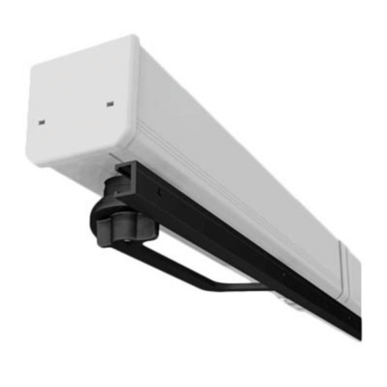
Bracci trasmissione (vedi tabelle successive) Guide scorrimento bracci Volantino sblocco manuale Carter copertura automazioni Carter copertura continua (OPZIONALE, articolo VLR04) Tappi chiusura laterale 10. Fascette chiusura/collegamento carter 11. Dispositivo batterie emergenza (OPZIONALE, articolo VLR05) 12. Dima foratura VLR02 VLR01SX VLR01DX... - Page 7 Persiana a 1 o 2 ante a pannello singolo, rientrante Tipo di braccio di trasmissione impiegabile VLR07 VLR08 A - Spazio minimo tra serramento interno e persiana 90 / 110 (senza batterie / con batterie VLR05) B - Larghezza vano (min/max) 1 anta, senza batterie (VLR01xx) 500 / 1050 500 / 1050...
-
Page 8: Verifiche Preliminari
Persiana a 1 o 2 ante a pannello doppio snodato Tipo di braccio di trasmissione impiegabile VLR08 VLR09 A - Spazio minimo tra serramento interno e persiana B - Larghezza vano (min/max) 1 anta, senza batterie (VLR01xx) 500 / 1050 500 / 1050 1 anta, con batterie (VLR01xx+VLR05) 750 / 1050... -
Page 9: Installazione
INSTALLAZIONE Le seguenti illustrazioni sono solo esempi. Spetta all'installatore scegliere la soluzione più adatta. Sulla dima sono sono riportate le indicazioni per l'utilizzo sia a destra che a sinistra. Tracciatura fori Appoggiare la dima alla persiana e alla spalletta del vano e segnare con una matita i punti di foratura indicati;... - Page 10 Fissaggio dell'automazione Se la larghezza del vano è inferiore alla dimensione della/delle basi dell'automazione, tagliare la/le parti eccedenti ❸. In tal caso non sarà possibile montare le batterie di emergenza (art. VLR05). Fissare l'automazione usando viti e tasselli adeguati. Nella configurazione a due ante battenti, installare l'automazione MASTER ❹...
- Page 11 Tagliare le guide di scorrimento della lunghezza necessaria lasciando un minimo di gioco alle estremità Persiana a 1 o 2 ante a pannello singolo Persiana a 1 o 2 ante a pannello doppio snodato Infilare il pattino del braccio nella guida di scorrimento (vedi dettaglio Fissare la guida alla persiana controllando la messa in bolla e lo...
- Page 12 Collegamento Master e Slave automazione VLR02 Attaccare le fascette fissacavo adesive ❻. Collegare il motoriduttore Slave all'automazione Master con il cavo cablato ❼ sul morsetto MOTOR1. In tale maniera, l'anta di destra aprirà per prima. Se è necessario aprire per primo l'anta di sinistra mantenendo il Master a destra, scambiare i connettori MOTOR1 e MOTOR2.
- Page 13 COLLEGAMENTI ELETTRICI E PROGRAMMAZIONE Il quadro comando è alimentato a 230 V AC, con frequenza 50/60Hz. I dispositivi di comando e gli accessori sono a 24 V. ⚠ Gli accessori non devono superare complessivamente i 15 W. Fusibili Tipo Linea (mA) Accessori (mA) Descrizione delle parti 10.
-
Page 14: Dispositivi Di Comando
AVER TOLTO LA TENSIONE. N.B.: La scheda base le riconosce solo quando viene alimentata. Scheda AF CRP - Came Remote Protocoll. Collegamento all'impianto domotico. Funzione APRE-STOP (contatto N.O.) Funzione CHIUDE-STOP (contatto N.O.) ⚠ Se sul pulsante collegato su 2 - 3 viene abilitata tramite DIP la funzione di APERTURA PARZIALE, in automatico il pulsante collegato su 2 - 4 funziona con il comando sequenziale APRE-STOP-CHIUDE-STOP. -
Page 15: Dispositivi Di Sicurezza
Dispositivi di sicurezza RIAPERTURA DURANTE LA CHIUSURA (N.C.). In fase di chiusura delle ante l'apertura del contatto provoca l'inversione del movimento fino alla completa apertura. Se i contatti 2-CX non sono utilizzati, ponticellare. Inserimento scheda 001AF43S - 001AF868 Scheda AF... - Page 16 Programmazione delle funzioni Prima di procedere alla programmazione delle funzioni, sbloccare i motoriduttori, chiudere manualmente le ante della persiana e ri-bloccare i motoriduttori. Come programmarla Come disporre Descrizione funzione i DIP ON OFF ON OFF Premere PROG sulla → Il LED rosso lampeggia. Programmazione corsa.
- Page 17 4 beep. ON ON OFF OFF Premere PROG sulla → Il LED rosso lampeggia. Memorizzazione trasmettitori scheda. CAME*. - Con i trasmettitori Rolling Code Entro 10 secondi, → A memorizzazione avvenuta il (TAM e TOP), la programmazione dei premere uno dei tasti buzzer emette un beep.
- Page 18 CAME REMOTE PROTOCOL Nel caso si utilizzi la scheda RSE, per attivare tutte le funzionalità del CRP, è necessario assegnare un indirizzo all'automazione (default 1 su tutte le automazioni) Indirizzo DIP SWITCHES Indirizzo DIP SWITCHES OPERAZIONI FINALI Fissare i tappi laterali utilizzando le viti in dotazione.
- Page 19 UNI EN ISO 14001 a garanzia del rispetto e della tutela dell’ambiente. Vi chiediamo di continuare l’opera di tutela dell’ambiente, che CAME considera uno dei fondamenti di sviluppo delle proprie strategie operative e di mercato, semplicemente osservando brevi indicazioni in materia di smaltimento: SMALTIMENTO DELL’IMBALLO...
- Page 20 CAME S.p.A. Via Martiri Della Libertà, 15 31030 Dosson di Casier - Treviso - Italy tel. (+39) 0422 4940 - fax. (+39) 0422 4941...
- Page 21 Shutter FA01031-EN operator VLR01DX - VLR01SX - VLR02 EN English INSTALLATION MANUAL...
-
Page 22: Read Carefully
• T HIS PRODUCT SHOULD ONLY BE USED FOR THE PUR GATE ANY DIRECT COMMANDS WHETHER BUT POSE FOR WHICH IT WAS EXPLICITLY DESIGNED . CAME S. TONS TOUCH PANELS AND SO ON MUST BE INSTALLED OTHER USE IS DANGEROUS... -
Page 23: Ordinary Maintenance
• W MOVING JOINTS AND SLIDE RAILS PROPERLY LUBRICATED YELLOW STRIPES HILE USING A SELECTOR SWITCH OR • I F REPAIRS OR MODIFICATIONS ARE REQUIRED TO THE A COMMAND IN MAINTAINED ACTIONS KEEP CHECKING SYSTEM RELEASE THE OPERATOR AND DO NOT USE IT UN THAT THERE ARE NO PERSONS WITHIN THE OPERATING •... - Page 24 All measurements, unless otherwise stated, are expressed in millimetres. REFERENCE REGULATIONS CAME S.p.A. the company is quality and environmentally certified by the ISO 9001 and the ISO 14001 respectively, for its management systems. This product complies with the current regulations mentioned in the declaration of conformity.
- Page 25 Technical data Type VLR01DX - VLR01SX VLR02 Protection rating (IP) Power supply (V - 50/60 Hz) 230 AC 230 AC Motor power supply (V) 24 DC 24 DC Current draw (A) 3 max 6 max Power (W) Opening time at 180° (s)
-
Page 26: Drilling Template
Master/Slave connection cable Transmission arms (see following tables) Arm slide-guides Manual release handwheel Protective carter for operators Continuous protective carter (OPTIONAL, item VLR04) End caps 10. Carter closing/connecting strips 11. Emergency battery device (OPTIONAL, item VLR05) 12. Drilling template VLR02 VLR01SX VLR01DX... - Page 27 One or two-leaved single panel retractable shutter Unfoldable type of transmission arm VLR07 VLR08 A - Minimum space between the inner fi xture and the shutter 90 / 110 (without batteries / with VLR05 batteries) B - Recess width (min/max) One leaf, without VLR01xx batteries 500 / 1050 500 / 1050...
-
Page 28: Preliminary Checks
One or two-leaved jointed double-panelled shutter Unfoldable type of transmission arm VLR08 VLR09 A - Minimum space between the inner fi xture and the shutter B - Recess width (min/max) One leaf, without VLR01xx batteries 500 / 1050 500 / 1050 One leaf, with VLR01xx+VLR05 batteries 750 / 1050 750 / 1050... -
Page 29: Installation
INSTALLATION The following illustrations are merely examples. It is up to the installer to find the most suitable solution. The template features the indications for use on both the right and left. Tracing the holes Rest the template against the shutters and the wall shoulder of the bay and using a pencil mark the holes;... - Page 30 Fastening the operator If the bay width is less than the dimensions of the operator base/bases, cut off any excess parts ❸. In such case, the emergency batteries (item VLR05) may not be mounted. Fit the operator using suitable screws and dowels. For the two swing-leaved configuration, install the MASTER operator ❹on the right and the SLAVE operator ❺...
- Page 31 Cut the slide rails to the required length, leaving a minimum of clearance at the ends One or two-leaved single panel shutter One or two-leaved jointed double-panelled shutter Fit the arm runner into the slide rail (see detail Fit the rail to the shutter, check that it is level and that the runner slides smoothly.
- Page 32 VLR02 operator Master and Slave connection Attach the adhesive cable strips ❻. Connect the Slave gearmotor to the Master operator using the wired cable ❼ to the MOTOR1 terminal. In this way, the right-hand leaf will open first. If you need the left-hand leaf to open first while keeping the Master to the right, exchange the MOTOR1 and MOTOR2 connectors.
-
Page 33: Description Of Parts
ELECTRICAL CONNECTIONS AND PROGRAMMING The control panel is powered by 230 V AC, with 50/60Hz frequency. The control devices and accessories run on 24 V. ⚠ The accessories must never exceed 15 W overall. Fuses Type Line (mA) Accessories (mA) Description of parts 10. - Page 34 AFTER CUTTING OFF THE MAINS POWER. N.B.: the basic control board recognizes them only when it is powered up. AF card CRP - Came Remote Protocol. Connection to the home automation system. OPEN-STOP function (NO contact) CLOSE-STOP function (NO contact) ⚠...
-
Page 35: Safety Devices
Safety devices REOPENING WHILE CLOSING (NC). When the gate leaves are closing, opening the contact causes their movement to invert, until they are completely open. If contacts 2-CX are unused, they should be bridged. 001AF43S - 001AF868 card fitting AF card... -
Page 36: Functions Programming
Functions programming Before programming functions, release the gearmotors, manually close the shutter leaves and re-lock the gearmotors. * Up to 25 codes can be stored between the transmitters and weather stations for the operator wireless control. How to program it Hoe to arrange the Function description DIPs... - Page 37 If the weather station is already memorized, the LED will fl ash quickly and the buzzer beeps 4 times. ON ON OFF OFF PROG on the card. → The red LED flashes. CAME transmitters memorizing* - With Rolling Code transmitters (TAM and TOP), the buttons programming is Within 10 seconds press →...
- Page 38 CAME REMOTE PROTOCOL If the RSE card is used, to activate all the CRP functions, it is necessary to assign an address to the operator (default 1 on all operators) Address DIP SWITCHES Address DIP SWITCHES FINAL OPERATIONS Fasten the end caps using the supplied screws.
- Page 39 UNI EN ISO 14001 regulation standard to ensure that the environment is respected and safeguarded. Please continue safeguarding the environment. At CAME we consider it one of the fundamentals of our operating and market strategies. Simply follow these brief disposal guidelines:...
- Page 40 CAME S.p.A. Via Martiri Della Libertà, 15 31030 Dosson di Casier - Treviso - Italy tel. (+39) 0422 4940 - fax. (+39) 0422 4941...
-
Page 41: Manuel D'installation
Automatisme FA01031-FR pour persiennes VLR01DX - VLR01SX - VLR02 FR Français MANUEL D'INSTALLATION... - Page 42 TION POUR LAQUELLE IL A ÉTÉ EXPRESSÉMENT CONÇU EXTRÊME PRUDENCE RÉVOIR SI NÉCESSAIRE DES INS OUTE AUTRE UTILISATION EST À CONSIDÉRER COMME TRUMENTS ADÉQUATS POUR UNE MANUTENTION EN TOUTE . CAME S. DANGEREUSE DÉCLINE TOUTE RES • T SÉCURITÉ OUTES LES COMMANDES D OUVERTURE PONSABILITÉ...
- Page 43 • I OU AUX PERSONNES DOTÉES D UNE EXPÉRIENCE ET D TOUT RISQUE L EST INTERDIT À L UTILISATEUR D EXÉ CONNAISSANCE INSUFFISANTES À MOINS QU ELLES NE CUTER DES OPÉRATIONS QUI NE LUI AURAIENT PAS ÉTÉ BÉNÉFICIENT PAR LE BIAIS D UNE PERSONNE RESPON EXPRESSÉMENT DEMANDÉES ET QUI NE SERAIENT PAS SABLE DE LEUR SÉCURITÉ...
-
Page 44: Utilisation Prévue
Les dimensions sont toutes exprimées en millimètres, sauf indication contraire. RÉFÉRENCES NORMATIVES CAME S.p.A. est une société certifiée pour les systèmes de gestion de la qualité ISO 9001 et de gestion environnementale ISO 14001. Ce produit est conforme aux normes en vigueur citées dans la déclaration de conformité. - Page 45 Données techniques Type VLR01DX - VLR01SX VLR02 Degré de protection (IP) Alimentation (V - 50/60 Hz) 230 AC 230 AC Alimentation moteur (V) 24 DC 24 DC Absorption (A) 3 max. 6 max. Puissance (W) Temps d’ouverture à 180° (s) Réglable...
-
Page 46: Description Des Parties
Volant de déblocage manuel Carter de protection des automatismes Carter de protection continue (EN OPTION, article VLR04) Embouts latéraux 10. Colliers de fermeture/raccordement carter 11. Dispositif batteries de secours (EN OPTION, article VLR05) 12. Gabarit de perçage VLR02 VLR01SX VLR01DX... - Page 47 Persienne à 1 ou 2 vantaux à panneau simple, rentrant Type de bras de transmission utilisable VLR07 VLR08 A - Espace minimum entre cadre interne et persienne 90 / 110 (sans batteries / avec batteries VLR05) B - Largeur encadrement (min./max.) 1 vantail, sans batteries (VLR01xx) 500 / 1050 500 / 1050...
-
Page 48: Contrôles Préliminaires
Persienne à 1 ou 2 vantaux à double panneau articulé Type de bras de transmission utilisable VLR08 VLR09 A - Espace minimum entre cadre interne et persienne B - Largeur encadrement (min./max.) 1 vantail, sans batteries (VLR01xx) 500 / 1050 500 / 1050 1 vantail, avec batteries (VLR01xx+VLR05) 750 / 1050... - Page 49 INSTALLATION Les illustrations suivantes ne sont que des exemples. C'est donc l'installateur qui doit choisir la solution la plus indiquée. Sur le gabarit apparaissent les indications pour l'utilisation aussi bien à droite qu'à gauche. Traçage des trous Poser le gabarit sur la persienne et l'embrasement puis signaler au crayon les points de perçage indiqués ;...
- Page 50 Fixation de l'automatisme Si la largeur de l'encadrement est inférieure aux dimensions de la/des bases de l'automatisme, découper la/les parties en trop ❸. Dans ce cas, il sera impossible d'installer les batteries de secours (art. VLR05). Fixer l'automatisme au moyen de vis et de chevilles appropriées.
- Page 51 Couper les rails de guidage selon la longueur nécessaire en prévoyant un jeu minimum aux extrémités Persienne à 1 ou 2 vantaux à panneau Persienne à 1 ou 2 vantaux à double panneau articulé simple Introduire le patin du bras dans le rail de guidage (voir détail Fixer le guide à...
- Page 52 Connexion Master et Slave automatisme VLR02 Coller les brides adhésives de fixation du câble ❻. Connecter le motoréducteur Esclave à l'automatisme Maître à l'aide du câble ❼ sur la borne MOTOR1. Ainsi faisant, le vantail de droite s’ouvrira en premier. Si nécessaire, ouvrir tout d'abord le vantail gauche en maintenant le Maître à...
- Page 53 BRANCHEMENTS ÉLECTRIQUES ET PROGRAMMATION L'armoire de commande est alimentée en 230 V AC, avec une fréquence de 50/60 Hz. Les dispositifs de commande et les accessoires sont alimentés en 24 V. ⚠ Les accessoires ne doivent pas dépasser tous ensemble 15 W. Fusibles Type Ligne (mA)
-
Page 54: Dispositifs De Commande
TENSION. N.B. : la carte de base ne les reconnaît que lorsqu'elle est alimentée. Carte AF CRP - Came Remote Protocoll. Connexion à l'installation domotique Fonction OUVERTURE-ARRÊT (contact N.O.) Fonction FERMETURE-ARRÊT (contact N.O.) ⚠ En cas d'activation par micro-interrupteurs DIP de la fonction d'OUVERTURE PARTIELLE sur le bouton connecté aux bornes 2 - 3, le bouton connecté... -
Page 55: Dispositifs De Sécurité
Dispositifs de sécurité RÉOUVERTURE DURANT LA FERMETURE (N.F.). Durant la phase de fermeture des vantaux, l'ouverture du contact provoque l'inversion du mouvement jusqu'à l'ouverture totale. Si les contacts 2-CX ne sont pas utilisés, les shunter. Installation carte 001AF43S - 001AF868 Carte AF... - Page 56 Programmation des fonctions Avant de lancer la programmation des fonctions, débloquer les motoréducteurs, fermer manuellement les vantaux de la persienne et bloquer de nouveau les motoréducteurs. Programmation de la fonction Description de la fonction Disposition des DIP ON OFF ON OFF Appuyer sur PROG sur la carte. → Le voyant rouge clignote. Programmation de la course.
- Page 57 En cas de centrale météo déjà mémorisée, le voyant clignote rapidement et le buzzer émet 4 bip. ON ON OFF OFF Appuyer sur PROG sur la carte. → Le voyant rouge clignote. Mémorisation des émetteurs CAME*. - Avec les émetteurs à code tournant (TAM et TOP), la programmation des Appuyer, dans les 10 secondes →...
- Page 58 CAME REMOTE PROTOCOL En cas d’utilisation de la carte RSE, pour activer toutes les fonctions du CRP, il est nécessaire d'attribuer une adresse à l’automatisme (par défaut 1 sur tous les automatismes) Adresse DIP SWITCHES Adresse DIP SWITCHES OPÉRATIONS FINALES Fixer les embouts latéraux à...
- Page 59 MISE AU REBUT ET ÉLIMINATION ☞ CAME S.p.A. adopte dans ses établissements un Système de Gestion Environnementale certifié et conforme à la norme UNI EN ISO 14001 qui garantit le respect et la sauvegarde de l'environnement. Nous vous demandons de poursuivre ces efforts de sauvegarde de l'environnement, que CAME considère comme l'un des fondements du développement de ses propres stratégies opérationnelles et de marché, en observant tout simplement de brèves...
- Page 60 CAME S.p.A. Via Martiri Della Libertà, 15 31030 Dosson di Casier - Treviso - Italy tel. (+39) 0422 4940 - fax. (+39) 0422 4941...
- Page 61 Автоматика FA01031-RU для ставен VLR01DX - VLR01SX - VLR02 RU Русский РУКОВОДСТВО ПО МОНТАЖУ...
- Page 62 ТО ИЗДЕЛИЕ ДОЛЖНО ИСПОЛЬЗОВАТЬСЯ ИСКЛЮ . Л СЛЕДУЙТЕ ПРИВЕДЕННЫМ НИЖЕ ИНСТРУКЦИЯМ НЕ ЧИТЕЛЬНО ПО НАЗНАЧЕНИЮ ЮБОЕ ДРУГОЕ ПРИ . CAME ПРАВИЛЬНАЯ УСТАНОВКА МОЖЕТ ПРИВЕСТИ К СЕРЬЕЗ МЕНЕНИЕ РАССМАТРИВАЕТСЯ КАК ОПАСНОЕ НЫМ ПОВРЕЖДЕНИЯМ СНИМАЕТ С СЕБЯ ВСЯКУЮ ОТВЕТСТВЕННОСТЬ М ЗА ВОЗМОЖНЫЙ УЩЕРБ...
- Page 63 . С УЧАСТОК АВТОМАТИКИ ЛЕДИТЕ ЗА ТЕМ ЧТОБЫ В КВАЛИФИКАЦИЕЙ И НЕОБХОДИМЫМИ ИНСТРУМЕНТАМИ ЗОНЕ РАБОТЫ АВТОМАТИКИ НЕ БЫЛО ПРЕПЯТСТВИЙ ВО ИЗБЕЖАНИЕ ВОЗНИКНОВЕНИЯ ОПАСНЫХ СИТУАЦИЙ Н • П Е ПОЗВОЛЯЙТЕ ДЕТЯМ ИГРАТЬ С ПЕРЕНОСНЫМИ ОЛЬЗОВАТЕЛЮ КАТЕГОРИЧЕСКИ ЗАПРЕЩАЕТСЯ ВЫ ИЛИ ФИКСИРОВАННЫМИ УСТРОЙСТВАМИ УПРАВЛЕНИЯ ПОЛНЯТЬ...
-
Page 64: Условные Обозначения
CAME S.p.A. имеет сертификат систем управления качеством ISO 9001 и сертификат охраны окружающей среды ISO 14001. Это изделие соответствует требованиям нормативов, указанных в декларации о соответствии. ОПИСАНИЕ Это изделие разработано и изготовлено компанией CAME S.p.A. в полном соответствии с действующими нормами безопасности. Корпус, защищающий электромеханический самоблокирующийся мотор-редуктор, изготовлен из силумина и снабжен алюминиевым кожухом. - Page 65 Технические характеристики Тип VLR01DX – VLR01SX VLR02 Класс защиты (IP) Электропитание (В, 50/60 Гц) ~230 ~230 Электропитание двигателя (В) =24 В =24 В Макс. потребляемый ток (A) 3 (макс.) 6 макс. Мощность (Вт) Время открывания на 180° (с) Регулируемое Регулируемое Интенсивного Интенсивного Интенсивность использования (%) использования...
-
Page 66: Описание Компонентов
Рычаги передачи (см. нижеследующие таблицы) Направляющие для рычагов Рычаг ручной разблокировки Кожух для автоматики Сплошной кожух (ОПЦИЯ, артикул VLR04) Боковые заглушки 10. Хомуты для закрытия/соединения кожуха 11. Система аварийного электроснабжения (ОПЦИЯ, артикул VLR05) 12. Шаблон для сверления отверстий VLR02 VLR01SX VLR01DX... - Page 67 Одно- или двусторчатые однопанельные ставни с заходом внутрь. Тип используемого рычага передачи VLR07 VLR08 A - Минимальное пространство между внутренним ограждением и ставнями 90 / 110 (без аккумуляторов / с аккумуляторами VLR05) B - Ширина проема (мин./макс.) 1 створка, без аккумуляторов (VLR01xx) 500 / 1050 500 / 1050 1 створка, с...
- Page 68 Одно- или двустворчатые двухпанельные ставни с шарниром. Тип используемого рычага передачи VLR08 VLR09 A - Минимальное пространство между внутренним ограждением и ставнями B - Ширина проема (мин./макс.) 1 створка, без аккумуляторов (VLR01xx) 500 / 1050 500 / 1050 1 створка, с аккумуляторами (VLR01xx+VLR05) 750 / 1050 750 / 1050 2 створки, без...
- Page 69 МОНТАЖ Приведенные ниже рисунки носят иллюстративный характер. Выбор наиболее подходящего решения должен осуществляться установщиком на месте. На шаблоне приведены указания относительно правостороннего и левостороннего монтажа. Определение мест отверстий с помощью шаблона Прислоните шаблон к ставням и откосу проема, отметьте карандашом указанные места для сверления; завершите разметку...
- Page 70 Крепление автоматики Если ширина проема меньше размеров основания/й автоматики, удалите лишнее ❸. В этом случае установка аккумуляторов аварийного питания будет невозможна (арт. VLR05). Прикрепите автоматику, используя подходящие винты и дюбели. В двустворчатых распашных системах ВЕДУЩАЯ автоматика (MASTER) ❹ должна устанавливаться справа, а...
- Page 71 Отрежьте направляющие требуемой длины, оставив минимальный зазор с двух концов Одно- или двустворчатые Одно- или двустворчатые двухпанельные ставни с шарниром. однопанельные ставни. Вставьте башмак рычага в направляющую (смотрите Зафиксируйте направляющую на ставнях, выровняв ее по горизонтали, и проверьте свободное движение башмака. Для...
- Page 72 Подключение ведущей и ведомой автоматики VLR02 Прикрепите хомуты ❻. Соедините ведомый (Slave) и ведущий (Master) приводы кабелем ❼ через подключение к контакту MOTOR1. Правая створка откроется первой. Если нужно, чтобы первой открывалась левая створка, а правая оставалась ведущей, необходимо поменять местами контакты MOTOR1 и MOTOR2. Разблокировка...
- Page 73 ЭЛЕКТРИЧЕСКИЕ ПОДКЛЮЧЕНИЯ И ПРОГРАММИРОВАНИЕ Для электропитания блока управления необходимо напряжение ~230 В с частотой 50/60 Гц. Для электропитания устройств управления и аксессуаров используется напряжение ~24 В. ⚠ Внимание! Суммарная мощность аксессуаров не должна превышать 15 Вт. Плавкие предохранители Тип Входной (мА) Аксессуары (мА) Описание компонентов платы...
- Page 74 разъем блока управления только ПОСЛЕ ОТКЛЮЧЕНИЯ ЭЛЕКТРОПИТАНИЯ. Важное примечание! плата блока Плата радиоприемника управления распознает их только после подачи на нее напряжения. CRP – Came Remote Protocol (протокол удаленного доступа CAME). Подключение к системе домашней автоматизации. Функция «ОТКРЫТЬ-СТОП» (Н.Р. контакты) Функция «ЗАКРЫТЬ-СТОП» (Н.Р. контакты) ⚠...
-
Page 75: Устройства Безопасности
Устройства безопасности ОТКРЫВАНИЕ В РЕЖИМЕ ЗАКРЫВАНИЯ (Н.З. контакты). Размыкание контакта во время закрывания ставен приводит к изменению направления движения на противоположное, вплоть до полного открывания. Если контакты 2-CX не используются, замкните их накоротко с помощью перемычки. Включение платы радиоприемника 001AF43S - 001AF868 Плата... - Page 76 Программирование функций и режимов работы Перед программированием режимов работы необходимо разблокировать приводы, закрыть створки ставен вручную и снова заблокировать приводы. Программирование DIP-переключателей Расположение DIP- Описание функции переключателей Нажмите кнопку PROG на плате. → Красный светодиодный ВКЛ ВЫКЛ ВКЛ ВЫКЛ Программирование движения. индикатор...
- Page 77 светодиодный индикатор начнет быстро мигать, а зуммер подаст 4 звуковых сигнала. Нажмите кнопку PROG на плате. → Красный светодиодный ВКЛ ВКЛ ВЫКЛ ВЫКЛ Программирование пультов ДУ CAME*. индикатор замигает. - Кнопки пультов ДУ с динамическим кодом (TAM и TOP) программируются автоматически: В течение 10 секунд нажмите → По завершении...
-
Page 78: Заключительные Работы
CAME REMOTE PROTOCOL Если используется плата RSE, для активации всех функций CRP необходимо назначить адрес для автоматики (по умолчанию 1 для всех автоматических устройств). Адрес DIP-ПЕРЕКЛЮЧАТЕЛИ Адрес DIP-ПЕРЕКЛЮЧАТЕЛИ ВЫКЛ ВЫКЛ ВЫКЛ ВЫКЛ ВЫКЛ ВЫКЛ ВЫКЛ ВЫКЛ ВЫКЛ ВКЛ ВКЛ ВЫКЛ... -
Page 79: Утилизация Упаковки
Укоротив центральный профиль до нужной длины (L1 = L - 14 мм), вставьте его в направляющие и зафиксируйте места соединений хомутами, сняв боковые заглушки ВЫВОД ИЗ ЭКСПЛУАТАЦИИ И УТИЛИЗАЦИЯ CAME S.p.A. использует на своих заводах сертифицированную систему экологического менеджмента, ☞ соответствующую стандарту UNI EN ISO 14001, чтобы обеспечить защиту окружающей среды. - Page 80 CAME S.p.A. Via Martiri Della Libertà, 15 31030 Dosson di Casier - Treviso - Italy tel. (+39) 0422 4940 - fax. (+39) 0422 4941...