
Related Manuals for Extron electronics PVT Series


Summary of Contents for Extron electronics PVT Series
- Page 1 User Guide PoleVault Wallplates ® PVT Series PoleVault Twisted Pair Input Wallplates (Decora and AAP models) ® PVT CV D, PVT RGB D Plus, PVT RGB D PVT CV AAP, and PVT RGB AAP 68-1259-01 Rev. D 07 12...
- Page 2 Precautions Safety Instructions • English Warning Power sources • This equipment should be operated only from the power source indicated on the product. This This symbol is intended to alert the user of important operating and maintenance equipment is intended to be used with a main power system with a grounded (neutral) conductor. The third (servicing) instructions in the literature provided with the equipment.
- Page 3 FCC Class A Notice This equipment has been tested and found to comply with the limits for a Class A digital device, pursuant to part 15 of the FCC Rules. Operation is subject to the following two conditions: This device may not cause harmful interference. This device must accept any interference received, including interference that may cause undesired operation.
- Page 4 CAUTION: A caution indicates a potential hazard to equipment or data. NOTE: A note draws attention to important information. Copyright © 2012 Extron Electronics. All rights reserved. Trademarks All trademarks mentioned in this guide are the properties of their respective owners.
-
Page 5: Table Of Contents
Final installation ..........14 Reference Material ........ Specifications ..........15 Part Numbers and Accessories ......18 PoleVault AV Input Plate Part Numbers ..18 Included Parts ..........18 Optional Accessories ........18 AAP Optional Parts ........18 PVT Series • Contents... - Page 6 PVT Series • Contents...
-
Page 7: Introduction
Introduction The section discusses basic information as an introduction to the PVT Series of twisted pair AV input wallplates. This section covers the following: • About the PVT Input Wallplates About the PVT Input Wallplates The Extron PVT Series PoleVault... -
Page 8: About The Pvt Cv D
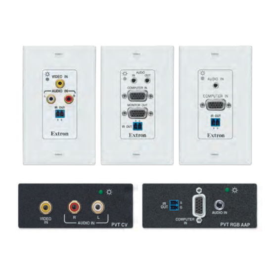
The PVT CV AAP fits a standard double space AAP opening and can transmit composite video and stereo audio to the PVS switcher. VIDEO AUDIO IN PVT CV Figure 2. PVT CV AAP face and rear panels PVT Series • Introduction... -
Page 9: About The Pvt Rgb D (Edid)
It can transmit computer (RGB) video and stereo audio to the PVS switcher. In addition, a 2-pole IR pass-through provides control connection for IR devices. AUDIO IN COMPUTER PVT RGB AAP Figure 5. PVT RGB AAP face and rear panels PVT Series • Introduction... - Page 10 Podcasting Software Document Camera E x tr Camera Extron VoiceLift Microphone and Charging Station (Optional Accessory) Figure 6. Typical PVT series system application using PVT Decora and AAP transmitters with the PVS 305SA and other Extron device. PVT Series • Introduction...
-
Page 11: Installation
Installation The section discusses the method of installation, cabling, and using EDID Minder of the PVT series wallplates. This section covers the following: • UL Safety Requirements • Installing the Wallplates Connections and Settings • • EDID Minder UL Safety Requirements The Underwriters Laboratories (UL) requirements listed below pertain to the safe installation and operation of these devices. -
Page 12: Installing The Pvt Cv And Pvt Rgb Decora Models
Features”, page 11, for connector wiring details. Connect input devices (see “Front Panel Features”, page 9, for connector details), restore the power supply, and test the wall plate. Make any cabling adjustments before final installation, as the cables will be inaccessible afterwards. PVT Series • Installation... -
Page 13: To Install Into A Wall Box
Repeat steps 1 and 2 to mount any other AAPs. Cover any openings in the faceplate with blank plates (provided with the AAP faceplate). Be sure to include the AAP connectors as part of the installation pretest before final installation of the faceplate. PVT Series • Installation... - Page 14 After testing and making any adjustments, turn off the power supply to the PoleVault switcher, and carefully secure the faceplate on the wall box device. Reconnect the cables and turn on the power supply to the switcher. This powers up the AAP plates. PVT Series • Installation...
-
Page 15: Connections And Settings
Connections and Settings The section discusses the method of cabling and using EDID Minder for the PVT series wallplates. This section covers the following: • Front Panel Features Rear Panel (Cabling and Features) • • EDID Minder • Final Installation CAUTION: Do not connect these devices to a computer data or telecommunications network. -
Page 16: Rear Panel
Insert Twisted with the TIA/EIA T 568A or T 568B Pair Wires White-brown White-brown RJ-45 Connector wiring standards, with the same Brown Brown standard used at both ends. DO NOT connect to an MTP system. PVT Series • Connections and Settings... -
Page 17: Rear Panel - Features
RGB A output (PVT RGB models) — Using CAT 5e or 6 UTPcable, connect this RJ-45 female output port labelled “RGB A out” to one of the input ports labelled A (for example, 2A) on the PoleVault switcher. PVT Series • Connections and Settings... - Page 18 EDID Minder 5-pole DIP switches according to the EDID table Minder” section, page 13 for details). (see “EDID Alternatively, if the EDID Minder is used in Learn mode, set all the DIP switches to off. PVT Series • Connections and Settings...
-
Page 19: Edid Minder
When the image is correct, re-install the wallplate. Re-connect and restart the source and display devices. Switch setting Preset Resolution Number Learn Mode (PVT RGB D Plus only) 800x600 1024x768 (default) 1280x720 1280x768 1280x800 1280x1024 1360x768 1366x768 1400x1050 1440x900 1600x1200 1680x1050 1920x1080 1920x1200 PVT Series • Connections and Settings... -
Page 20: Using Learn Mode (Available On Pvt Rgb D Plus Only)
N IT Extron PVT RGB D Plus (EDID) Figure 16. Mounting the PVT RGB D Plus (EDID) Reconnect the cables and turn on the power supply to the switcher This powers up the wall plates. PVT Series • Connections and Settings... -
Page 21: Reference Material
Max. input voltage ......5.5 Vp-p Video — composite video Gain ..........Unity Differential phase error ....<1.0° at 3.58 MHz and 4.43 MHz Differential gain error ..... <1.0% at 3.58 MHz and 4.43 MHz PVT Series • Reference Material... - Page 22 Furniture or wall mount PVT CV D, PVT RGB D, PVT RGB D Plus Yes, with the included Decora wall plate ® PVT CV AAP, PVT RGB AAP Yes, with optional faceplates or AAP wall plates PVT Series • Reference Material...
- Page 23 Safety ........CE, c-UL, UL EMI/EMC ......... CE, C-tick, FCC Class A, ICES, VCCI MTBF ..........30,000 hours Warranty ........3 years parts and labor NOTES: All nominal levels are at ±10%. Specifications are subject to change without notice. PVT Series • Reference Material...
-
Page 24: Part Numbers And Accessories
60-300-02, 03 AAP 104 panel, black, white 60-301-02, 03 AAP 201 panel, ½ rack width, 1U, black 60-302-02 AAP 301 panel, 1 rack width, 1U, black 60-632-02 AAP 302 panel, 1 rack width, 2U, black 60-633-02 PVT Series • Reference Material... - Page 25 PVT Series • Reference Material...
- Page 26 Extron Electronics makes no further warranties either expressed or implied with respect to the product and its quality, performance, merchantability, or fitness for any particular use. In no event will Extron Electronics be liable for direct, indirect, or consequential damages resulting from any defect in this product even if Extron Electronics has been advised of such damage.