Extron electronics PVS 405D User Manual
Polevault digital switcher
Hide thumbs
Also See for PVS 405D:
- Installation manual (84 pages) ,
- User manual (51 pages) ,
- Installation manual (46 pages)
Table of Contents
Advertisement
Quick Links
Download this manual
See also:
Installation Manual
Advertisement
Table of Contents

Related Manuals for Extron electronics PVS 405D


Summary of Contents for Extron electronics PVS 405D
- Page 1 User Guide POLEVAULT SWITCHERS PVS 405D PoleVault Digital Switcher 68-2379-01 Rev. A 03 14...
-
Page 2: Safety Instructions
Safety Instructions Safety Instructions • English Инструкция по технике безопасности • Русский WARNING: This symbol, , when used on the product, is intended to alert the user ПРЕДУПРЕЖДЕНИЕ: Данный символ, , если указан на продукте, of the presence of uninsulated dangerous voltage within the product’s enclosure that предупреждает... - Page 3 “Extron Safety and Regulatory Compliance on the Extron website. Guide” Copyright © 2014 Extron Electronics. All rights reserved. Trademarks All trademarks mentioned in this guide are the properties of their respective owners. The following registered trademarks ®...
-
Page 4: Conventions Used In This Guide
Conventions Used in this Guide Notifications The following notifications are used in this guide: DANGER: A danger indicates a situation that will result in death or severe injury. WARNING: A warning indicates a situation that has the potential to result in death or severe injury. -
Page 5: Table Of Contents
Installing the Software ........31 Power ............. 5 Labeling the AV Inputs ........6 Installation from the Website ......31 Starting the PVS 405D Product Configuration Labeling the PVT Decora face plates ....6 Software ............32 Final Setup ............7 Using the PVS 405D Product Configuration Securing the HDMI cable ........ - Page 6 TP Cable Termination and Recommendations .. 46 Power Supply Wiring ........47 RS‑232 Connector Wiring ........ 48 For IR communication ........49 Input 5 Connector Wiring ........51 Warranty ..............52 Contact Information ........... 52 PVS 405D Switcher • Contents...
-
Page 7: Introduction
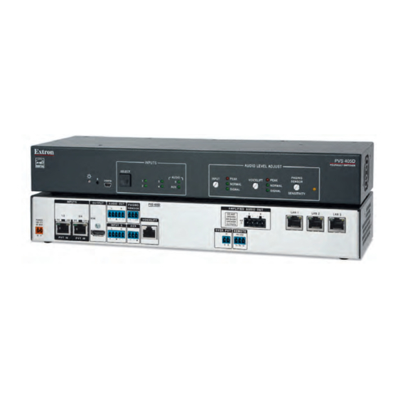
PVS 405D or the PoleVault switcher or just the switcher. PVS 405D Description The Extron PVS 405D is part of the PoleVault System and is used in conjunction with the Extron PVT series of transmitters and Extron speakers. It has four video and audio twisted pair inputs with one HDMI output, and has a built‑in audio amplifier. -
Page 8: Outputs
Outputs The PVS 405D has one HDMI output, an amplified audio output, and a line out audio output for assistive listening or recording devices. Control and Configuration The PoleVault switcher can be controlled from either the front panel buttons, or software via the front panel USB or RS‑232 control via a MediaLink controller. -
Page 9: Application Diagram
P LA with Charging Station with Charging Station O FF Document D VD Camera M LC 4 IP Blu-ray Player P LU Extron MLC 104 IP Plus MediaLink Controller Figure 1. Typical PVS 405D Application PVS 405D Switcher • Introduction... -
Page 10: Rear Panel Connections
Rear Panel Connections This section describes which cables to connect to a PVS 405D Switcher. Rear Panel Connectors The illustration below shows the rear panel features of the PVS 405D. PVS 405D INPUTS INPUTS OUTPUT OUTPUT AUDIO OUT AUDIO OUT... -
Page 11: Outputs
MLC 104 IP PLUS MLS PWR RS-232 12V Figure 3. MLC 104 IP Plus RS-232 and IR Connections to the PVS 405D LAN ports — Connect to these three RJ‑45s that act as a built‑in 3‑port 10/100Base‑T network switch. Power Power receptacle —... -
Page 12: Labeling The Av Inputs
Use only the supplied 12 V, 4 A power supply for this switcher. • The PVS 405D power supply can support a typical system: for example, a PVS 405D, 2 PVT Wallplates, 2 or 4 speakers, an MLC 104 IP Plus with an IRCM DV+, and a VoiceLift Microphone system. •... -
Page 13: Final Setup
Final Setup With an MLC 104 IP Plus as a standard MLC controller in the PoleVault system package, the PVS 405D switcher completed setup should look similar to the figure below. Ensure all connections are correctly made and secure. NOTE: See the PoleVault System Installation Guide and MLC 104 Plus Series Setup Guide for full MLC installation, configuration, and operating details. -
Page 14: Operation
Operation This section of the manual discusses the operation of a PVS 405D device. Topics covered include: Front Panel Overview • Configuration • Resetting the Switcher • Front Panel Lockout (Executive Modes) • Power Save Modes • Setting Up and Optimizing the Audio •... -
Page 15: Front Panel Operation
Configuration The PVS 405D switcher can be controlled by a MediaLink Controller (MLC) or by an RS‑232 device acting through the MLC. Alternatively, the switcher can be set up and controlled via a host computer or other device (such as a control system) attached to the front panel USB connector, or to the rear panel RS‑232 remote port of the switcher. -
Page 16: Resetting The Switcher
The reset button on the front panel is a small recessed switch that allows the user to put the switcher into two different reset modes. The PVS 405D switcher reset modes are: Mode 1: If the Reset Button is held down while the switcher is being powered up, the •... -
Page 17: Power Save Modes
Power Save Modes The PVS 405D is an ENERGY STAR qualified device, and has five power modes. See table below for mode descriptions. See the “SIS Communication and Control” section, page 24 for relevant commands. Mode Type Activation Device and... -
Page 18: Setting Up And Optimizing The Audio
Refer to the transmitters’ user’s manual for installation/connection information. Ensure a set of speakers are connected to the PVS 405D. Adjust the input sensitivity for one input through the front panel or by configuration software to a level just below where audio input is peaking. -
Page 19: Gain Control
Control” for details on SIS commands). Repeat the steps for the other inputs as desired. NOTE: The Peak/Normal/Signal LEDs function as the Aux Input level indicator only when the switcher is in the “AUX Adjust” mode. PVS 405D Switcher • Operation... -
Page 20: Bass And Treble Control
NOTE: If audio output is muted via the “1Z” SIS command, all audio will not be heard. The VoiceLift Microphone input can be muted via a separate SIS command. See the “SIS Communication and Control” section, for details. PVS 405D Switcher • Operation... -
Page 21: Paging Sensitivity Adjustment
This is to prevent the audio to be un‑muted if the person pauses or stops talking while making the announcement or page. PVS 405D Switcher • Operation... -
Page 22: Sis Communication And Control
Switcher-initiated Messages When a local event such as a front panel selection or adjustment takes place, the PVS 405D responds by sending a message to the host. No response is required from the host. Example switcher‑initiated messages are listed here. -
Page 23: Error Responses
Error Responses When the PVS 405D receives a valid command, it executes the command and sends a response to the host device. If the unit is unable to execute the command because the command contains invalid parameters, it returns an error response to the host. -
Page 24: Symbol Definitions
3 = Source is not encrypted or detected, sink is connected but HDCP status is unknown X1& = HDMI input HDCP Authorization status: 0 = Block HDCP encryption 1 = Allow HDCP encryption (default) PVS 405D • SIS Communication and Control... - Page 25 = Native resolution and refresh rate from selected EDID = Total pixels — ±255 of the default value (depends on input rate) X2& = Pass‑through mode: 0 = Not in pass‑through mode (default) 1 = In pass‑through mode PVS 405D • SIS Communication and Control...
- Page 26 2 = input 2 4 = input 4 X3& = Pixel phase ‑ 0‑63 (32 = default) X3* = Horizontal start ‑ 0‑255 (128 = default) X3( = Vertical start ‑ 0‑255 (128 = default) PVS 405D • SIS Communication and Control...
- Page 27 1Q = Firmware version [<currently running code (X.YY)>] 2Q = Final stage bootloader (Uboot) version [<X.YY>] 3Q = Factory base code version [<factory base code (X.YY)>*] 4Q = Updated firmware version [<updated code version (X.YY)>*] PVS 405D • SIS Communication and Control...
-
Page 28: Sis Command And Response Table
X! = Input number: 1 through 5 X$ = Audio Input: 1 = Active program (post switch), 7 = VoiceLift, 8 = Aux X3@ = On/Off: 0 = off/disable, 1 = on/enable (mute to black) PVS 405D • SIS Communication and Control... - Page 29 X3# = Audio output volume: 000 to 100 (‑100dB to 0dB, in 1 dB steps), default 80 X3% = Input audio gain and attenuation: ‑18 to +24 dB V, in 1 dB steps Inputs 1‑5 and 8; default is 0 dB Input 7 (VoiceLift); default is ‑3 dB PVS 405D • SIS Communication and Control...
- Page 30 4 = Force network standby power save on (turn off network switch) X2( = Temperature in °C. The response is 3 digits with leading zeros X3@ = On/off status: 0 = off/disable; 1 = on/enable PVS 405D • SIS Communication and Control...
- Page 31 X3) = Relay status (VLR 102 response) 0 = Off 1 = On X3! = Contact closure input state (VLR 102 response) 0 = Open 1 = Closed X3@ = On/off status: 0 = off/disable; 1 = on/enable PVS 405D • SIS Communication and Control...
-
Page 32: Hdcp Status
X1( = HDCP input selection; inputs 1‑4 only. X2) = EDID in HEX format: 128 or 256 Byte EDID raw HEX (text form) X2! = Native resolution and refresh rate from selected EDID. PVS 405D • SIS Communication and Control... -
Page 33: Special Functions
X3^ = PVT SW HDMI RGB D inputs 2 and 4 only 2 = input 2 4 = input 4 X3& = Pixel phase ‑ 0‑63 (32 = default) X3* = Horizontal start ‑ 0‑255 (128 = default) PVS 405D • SIS Communication and Control... - Page 34 1Q = Firmware version [<currently running code (X.YY)>] 2Q = Final stage bootloader (Uboot) version [<X.YY>] 3Q = Factory base code version [<factory base code (X.YY)>*] 4Q = Updated firmware version [<updated code version (X.YY)>*] PVS 405D • SIS Communication and Control...
- Page 35 1Q = Firmware version [<currently running code (X.YY)>] 2Q = Final stage bootloader (Uboot) version [<X.YY>] 3Q = Factory base code version [<factory base code (X.YY)>*] 4Q = Updated firmware version [<updated code version (X.YY)>*] PVS 405D • SIS Communication and Control...
- Page 36 PVS 405D • SIS Communication and Control...
-
Page 37: Using The Extron Product Configuration Software
Software The Extron PVS 405D Product Configuration Software (PCS) offers another way to control the PVS 405D via USB or rear panel RS‑232 connection, in addition to using the SIS commands. This section describes installation, communication, and control. The topics include: Installing the Software •... -
Page 38: Starting The Pvs 405D Product Configuration Software
In the Device Name field, enter the name of the device, or Click on Connect to Online Devices, Start New Device File. See the PVS 405D Product Configuration Software Help file for full details. Click Open Device, Connect, or Select Device as required. A new tab opens from which you can configure the device. -
Page 39: Using The Pvs 405D Product Configuration Software - Menus
New Device Page in Emulate/Offline Mode Using the PVS 405D Product Configuration Software — Menus NOTE: For detailed software navigation open the PVS 405D Product Configuration Software Help file. There are two main menus shown at the top of the window. -
Page 40: Tools Menu
All audio, video, input configuration settings, HDCP settings, EDID Minder settings and audio settings from a PVS 405D can be exported to a PC using the Windows Control Program. This exported device file (*.eaf) can be saved as a backup, or be used to “clone”... - Page 41 Click Update. The progress bar shows the progress of the firmware upload to the device. After uploading is completed, the device restarts. Reconnection to the device must be made to enable live configuration. PVS 405D • Using Extron Product Configuration Software...
-
Page 42: Using The Pvs 405D Product Configuration Software - Pages
Using the PVS 405D Product Configuration Software — Pages There are two main pages for configuring the PVS 405D: the Configuration page and the Hardware page. Configuration Pages NOTE: From the Hardware page, click on the Configuration tab The Configuration pages options are: •... -
Page 43: Input Configuration Page
The HDCP Authorized is only available for HDCP inputs. NOTE: EDID Assignment This shows the EDID resolution and rate for the digital inputs (1‑4) only. Output format Output format for all video signals is always HDMI. PVS 405D • Using Extron Product Configuration Software... -
Page 44: Edid Minder Page
From this page an EDID data set can be assigned to any input with an RGB or an HDMI or DVI input type. The currently assigned EDID properties can be viewed and EDID files can be loaded to and from the PVS 405D. EDID Minder Page Figure 19. - Page 45 Click the Assign All button. NOTE: If you select Assign All, all input boxes, checked or unchecked, will be ignored and the EDID will be assigned to all inputs. PVS 405D • Using Extron Product Configuration Software...
-
Page 46: Audio Settings Page
Fixed) for volume adjustment. Click and drag the handle of the Volume slider or click the up > and down < arrows in the field below the slider, or enter a value in the field. PVS 405D • Using Extron Product Configuration Software... - Page 47 Select the Enable Paging Sensor checkbox. The Hold Time field become active. Click the Up and Down Arrows in the field, or enter a value in the field. The range is 1 to 8 seconds. PVS 405D • Using Extron Product Configuration Software...
-
Page 48: Hardware Pages
NOTE: The device name can only contain alpha‑numerical characters and dashes and hyphens. Click the Hardware button above the global navigation bar. Click the Device Name icon on the global navigation bar. The Device Name screen dialog box opens. PVS 405D • Using Extron Product Configuration Software... -
Page 49: Executive/Power Mode Page
Click on this button to open the page. Figure 26. Executive/Power Mode Page Executive Mode Executive mode locks the front panel functions of the PVS 405D, and there are two executive mode options available: Unlock Front Panel (default) • Lock Front Panel •... - Page 50 Click Reset. A confirmation dialog box opens. In the dialog box, click Reset to continue with the reset, or Cancel to abort the reset. A confirmation dialog box appears confirming the device has been reset. PVS 405D • Using Extron Product Configuration Software...
-
Page 51: Connector Wiring
Connector Wiring This section of the manual discusses the connector wiring for a PVS 405D device. Topics covered include: Speaker Configuration • TP Cable Termination • Power Supply Connector Wiring • RS-232 Connector Wiring • Input 5 Connector Wiring •... -
Page 52: Terminating The Speaker Cable
Figure 31. TP Cable Termination ATTENTION: The PoleVault signal transmission method is specific for PVS 405D switchers working with PVT digital wallplates. DO NOT connect the input ports to an MTP system or to an Ethernet/LAN or data transmission system. -
Page 53: Power Supply Wiring
NOTE: Use only the supplied 12 V, 4 A power supply for this switcher. The PVS 405D power supply can support a typical system: for example, a PVS 405D, 2 PVT Wallplates, 2 or 4 speakers, an MLC 104 IP Plus with an IRCM DV+, and a VoiceLift Microphone system. -
Page 54: Rs-232 Connector Wiring
RS-232 Connector Wiring Figure shows the wiring for the PVS 405D and the MLC 104 IP Plus RS‑232 connectors . REMOTE PVS 405D RS-232 Remote RS-232 Port Tx Rx G NOTE: You must connect a ground wire between the MLC and PVS 405D. -
Page 55: For Ir Communication
Comm Cable 9-Pin Female Black NOTE: Red and black not used. NOTE: White, violet, and shield not used. White Shield Black Violet DISPLAY DISPLAY RS-232/IR RS-232/IR MLC 104 IP Plus Figure 37. IR Emitter Cable Connection PVS 405D • Connector Wiring... - Page 56 IR control for a connected input device such as a BluRay player can be made through the PVT wallplate. The connections between the MLC 104 IP Plus and the PVS 405D switcher should look like the figure below. PVS 405SA IP...
-
Page 57: Input 5 Connector Wiring
Ring Balanced Audio Input Balanced Mono Input (high impedance) Sleeve Sleeve Sleeve Unbalanced Stereo Input Unbalanced Mono Input Aux Audio Audio Input Input 5 Do not tin the wires! Figure 39. Input 5 Audio Wiring PVS 405D • Connector Wiring... -
Page 58: Warranty
Extron Electronics makes no further warranties either expressed or implied with respect to the product and its quality, performance, merchantability, or fitness for any particular use. In no event will Extron Electronics be liable for direct, indirect, or consequential damages resulting from any defect in this product even if Extron Electronics has been advised of such damage.