Table of Contents
Advertisement
Quick Links
Install the Device
Before you begin this task, ensure that you have read and understood the safety warnings in the Standard
Warning Statements section of the Safety Warnings handout.
Installing the Cisco NCS 540 Small Density routers involves these tasks:
Note
•
•
Rack Compatibility
We recommend that you follow these rack specifications.
Rack Types
Figure 1: Rack specification EIA (19 inches and 23 inches)
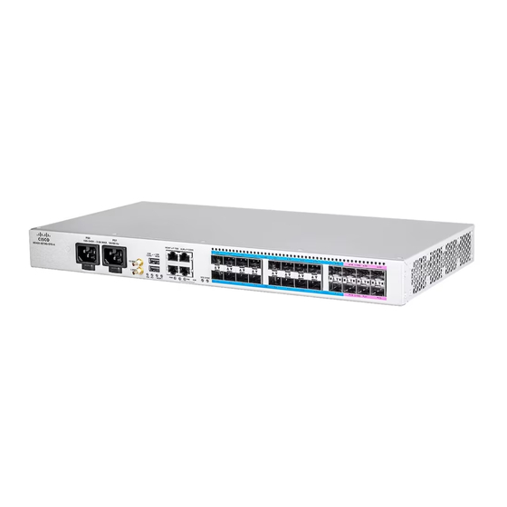
All the installation instructions for N540X-6Z18G-SYS-A/D, N540X-8Z16G-SYS-A/D, and
N540X-4Z14G2Q-A/D variants remain similar and any differences between the routers are specifically
called out.
The illustrations are for reference purpose only and may vary based on your Cisco NCS 540 variant.
Rack Compatibility, on page 1
Set up Device on Rack or Wall, on page 3
Install the Device
1
Advertisement
Table of Contents

Related Manuals for Cisco N540X-6Z18G-SYS-A


Summary of Contents for Cisco N540X-6Z18G-SYS-A
- Page 1 All the installation instructions for N540X-6Z18G-SYS-A/D, N540X-8Z16G-SYS-A/D, and N540X-4Z14G2Q-A/D variants remain similar and any differences between the routers are specifically called out. The illustrations are for reference purpose only and may vary based on your Cisco NCS 540 variant. • Rack Compatibility, on page 1 •...
- Page 2 Install the Device Rack Types Table 1: Rack specification EIA (19 inches and 23 inches) Post Type Rack Type Rack Front Opening Rack Mounting Hole Mounting Flange Centre-Centre (Y) Dimension (Z) 4 Post 19 inches (48.3 17.75 inches (45 18.31 inches (46.5 19 inches (48.2 centimeters) centimeters)
-
Page 3: Rack Mount
Figure 3: Two Post Rack Type Set up Device on Rack or Wall You can choose to either set up the Cisco NCS 540 on a rack or wall mount it. Rack Mount The device is shipped with rack mounting brackets that are to be secured on the sides of the device. - Page 4 Install the Device Rack Mount Quantity Part Description 1 (32-0619-01) LUG, FAST, UNIN, #6AWG, #10, 2 HOLES 4 (48-101690-01) SCR, M, PAN, PH, 12-24 x 0.49"L, CSwZN, nickel alloy To mount the rack on the router: 1. Attach the rack-mount brackets and the cable guides to the router as follows: a.
- Page 5 Install the Device Rack Mount Figure 5: Installing Cable Management and 19 inch Rack-Mount Brackets in the Front Figure 6: Installing 19 inch Rack-Mount Brackets in the Middle Install the Device...
- Page 6 Install the Device Rack Mount Figure 7: Installing Cable Management and 19 inch Rack-Mount Brackets in the Middle Figure 8: Installing Cable Management and 23 inch Rack-Mount Brackets in the Middle Install the Device...
- Page 7 Install the Device Rack Mount Figure 9: Installing Cable Management and 23 inch Rack-Mount Brackets in the Front Figure 10: Installing Cable Management and ETSI Rack-Mount Brackets in the Front Install the Device...
- Page 8 Tighten the 12-24 screws to 30 in-lb (3.39 N.m). Install the N540-6Z18G-SYS-A/D router with Air Plenum Note Air plenum is only applicable for Cisco N540-6Z18G-SYS-A/D router. Plenum Assembly on ETSI Rack 1. Remove the screws on the sides of the chassis, according to your mounting option: •...
- Page 9 Install the Device Install the N540-6Z18G-SYS-A/D router with Air Plenum Figure 12: Remove Screws from the Sides of the Chassis Left side of the chassis Right side of the chassis Screw 2. Fix the plenum (800-110707-01) with help of six screws (48-101850-01). Figure 13: Fix the Plenum with Screws Air Plenum Screw...
- Page 10 Install the Device Install the N540-6Z18G-SYS-A/D router with Air Plenum • For front mount (refer image A), fix the mounting bracket in the front and the dummy cover at the rear. • For mid mount (refer image B), fix the mounting bracket in the mid and the dummy cover at the front.
- Page 11 Install the Device Install the N540-6Z18G-SYS-A/D router with Air Plenum Figure 16: Fix Assembly to Rack Screw 8. Fix the cable bracket (700-114387-01) to the assembly with the help captive screws in the cable bracket. Figure 17: Fix Cable Bracket to the Assembly Cable Bracket Captive Screw Figure 18: ETSI and Air Plenum Assembly...
- Page 12 Install the Device Install the N540-6Z18G-SYS-A/D router with Air Plenum 1. Remove the screws on the sides of the chassis, according to your mounting option: • To front mount the chassis, remove four screws on the right side of the chassis. The “F” highlighted screws.
- Page 13 Install the Device Install the N540-6Z18G-SYS-A/D router with Air Plenum Air Plenum Screw 3. Fix the mounting bracket (700-129948-01) with the help of four screws (48-101850-01), according to your mounting option. • For front mount (refer image A), fix the mounting bracket in the front and the dummy cover at the rear.
-
Page 14: Wall Mount
Install the Device Wall Mount Bracket Bracket Screw Cable Bracket Mounting Bracket Screw 8. Fix the assembly to rack with the help of four screws (48-101690-01). Figure 23: Fix the Assembly to Rack Screw 9. Fix the cable bracket (700-114387-01) to the assembly with the help of captive screws in the cable bracket. Figure 24: Fix Cable Bracket to the Assembly Cable Bracket Captive Screw... -
Page 15: Ground The Device
Install the Device Ground the Device Note Wall mount is currently not available on NCS 540 Small Density Routers. Contact your Cisco representative if you need a wall mount. Ground the Device Before you begin this task, ensure that you have read and understood the safety warnings in the Preventing ESD Damage section of the Safety Warnings handout. - Page 16 4. Tighten the tie around the power supply cord as shown. Note These images are for only representation purposes. Certain variants of Cisco NCS 540 routers don’t include a tie for the power supply cord. Activate an AC Power Supply Module Perform the following procedure to activate an AC power supply: 1.
- Page 17 Install the Device Install the DC Power Cables 2. Connect the other end of the power cord to an AC-input power source. 3. Verify power supply operation by checking if the respective power supply front panel LED (PS0 or PS1) is green.
- Page 18 Install the Device Install the DC Power Cables Figure 26: DC Connector with In built Screw To attach the DC power supplies: 1. Locate the terminal block plug. 2. Insert the DC-input power source wires into the terminal block plug. 3.
- Page 19 Install the Device Activate a DC Power Supply Module Figure 27: Attach the DC Power Supply Wires Activate a DC Power Supply Module Perform the following procedure to activate a DC power supply: 1. Verify the power supply operation by checking whether the respective power supply front panel LED (PS0 or PS1) is green.
-
Page 20: Connect To The Console Port
• Download software updates. The system console port is an RJ-45 receptacle for connecting a data terminal to perform the initial configuration of Cisco NCS 540 fixed-port chassis. You can connect the router to the computer USB port using the following options: •... - Page 21 Install the Device Connect to the Console Port 2. The settings are the following: • Baud rate: 115200 • Data: 8 • Parity: none • Stop bit:1 Install the required driver from the following link: https://www.maxlinear.com/product/interface/uarts/usb-uarts/xr21v1410 Figure 28: Connect Using USBA-A Cable Console Port USB Type-A console cable •...
- Page 22 Install the Device Connect to the Management Ethernet Port • Figure 29: Connecting the USB Console Cable to the Chassis RJ45 Port Serial to RJ45 Console Adapter Cable USB to Serial Interface Cable Following table represents the RJ-45 cable pin-out information. Table 4: RJ-45 Straight-through Cable Pin-outs RJ-45 Pin Signal...
-
Page 23: Connecting Timing Cables
The timing features are not applicable to Cisco N540-6Z18G-SYS-A/D router. Connecting Cables to a GPS Interface The following sections describe how to connect cables from the Cisco NCS 540 Small Density router to a GPS unit for input or output timing: Connecting a Cable to the Input 10-MHz or 1-PPS Interface 1. -
Page 24: Install And Remove Sfp Modules
Install the Device Connecting a Cable to the Output 10-MHz or 1-PPS Interface 2. Connect the other end of the mini-coax cable to the 10-MHz or 1-PPS port on the front panel of the Cisco NCS 540 Small Density router. - Page 25 Install the Device Bale Clasp SFP or SFP+ Module Figure 30: SFP/SFP+ Module Cage Cover Caution Protect the SFP or SFP+ modules by inserting clean dust covers into them after the cables are removed. Be sure to clean the optic surfaces of the fiber cables before you plug them back into the optical ports of another module.
- Page 26 Install the Device Install a Bale Clasp SFP or SFP+ Module Figure 31: Bale Clasp SFP or SFP+ Module Install a Bale Clasp SFP or SFP+ Module To install this type of SFP or SFP+ module, follow these steps: 1. Attach an ESD-preventive wrist or ankle strap and follow its instructions for use. 2.
- Page 27 Install the Device Remove a Bale Clasp SFP or SFP+ Module Note When installing an SFP or SFP+ module, you should hear a click as the triangular pin on the bottom of the SFP module snaps into the hole in the receptacle. This click indicates that the module is correctly seated and secured in the receptacle.
- Page 28 Install the Device Connect Interface Ports Figure 33: Removing a Bale Clasp SFP or SFP+ Module 5. Place the SFP module that you removed on an antistatic mat, or immediately place it in a static shielding bag if you plan to return it to the factory. 6.
- Page 29 Install the Device Connect a Fiber-Optic Port to the Network Connect a Fiber-Optic Port to the Network Some transceivers work with fiber-optic cables that you attach to the transceivers and other transceivers work with pre-attached copper cables. When installing fiber-optic cables for a port, you must install SFP transceivers for 1-Gigabit optical ports or install SFP+ transceivers for 10-Gigabit optical ports before installing the fiber-optic cable in the transceivers.
- Page 30 Install the Device Maintain Transceivers and Optical Cables Install the Device...