Advertisement
Quick Links
Installation Guide
D102775X014
English - November 2022
Introduction
This installation guide provides instructions for installation,
startup and adjustment. To receive a copy of the instruction
manual, contact your local Sales Representative or view
a copy at www.fisher.com. For further information refer to:
ACE95 Series Instruction Manual, D102775X012.
PED Categories
This product may be used as a safety accessory with pressure
equipment in the following Pressure Equipment Directive
categories. It may also be used outside of the Pressure
Equipment Directive using sound engineering practice (SEP)
per table below. For information on the current PED revision see
Bulletin: D103053X012.
PRODUCT TYPE
PRODUCT SIZE
DN 20 / NPS 3/4
ACE95
DN 25 / NPS 1
ACE95Sr
DN 50 / NPS 2
Specifications
Sizes and End Connection Styles
See Table 1
Maximum Operating Inlet Pressure
13.8 bar / 200 psig
Maximum Outlet (Casing) Pressure
1.4 bar / 20 psig
Maximum Operating Outlet Pressure
0.10 bar / 1.5 psig
Outlet (Control) Pressure Ranges
See Table 2
Proof Test Pressure
All Pressure Retaining Components have been proof
tested per Directive.
Material Temperature Capabilities
Nitrile (NBR): -29 to 82°C / -20 to 180°F
Fluorocarbon (FKM): -18 to 100°C / 0 to 212°F
Ethylenepropylene (EPDM/FDA)
-29 to 100°C / -20 to 212°F
Perfluoroelastomer (FFKM):
-29 to 100°C / -20 to 212°F
Installation
!
Only qualified personnel should install
or service a regulator. Regulators should
be installed, operated and maintained in
accordance with international and applicable
codes and regulations and Emerson Process
Management Regulator Technologies,
Inc. instructions.
1. The pressure/temperature limits in this installation guide and any applicable standard or code limitation should not be exceeded.
2. FDA/USP Class VI approved/ADI-free elastomers (wetted parts only).
CATEGORIES
FLUID TYPE
SEP
I
(1)
(1)
(1)
(1)
(1)
:
(2)
WARNING
If the regulator vents fluid or a leak develops in
the system, it indicates that service is required.
Failure to take the regulator out of service
immediately may create a hazardous condition.
Personal injury, equipment damage or
leakage due to escaping fluid or bursting of
pressure-containing parts may result if this
regulator is over-pressured or is installed
where service conditions could exceed the
limits given in the Specifications section, or
where conditions exceed any ratings of the
adjacent piping or piping connections.
To avoid such injury or damage, provide
pressure-relieving or pressure-limiting
devices (as required by the appropriate code,
regulation or standard) to prevent service
conditions from exceeding limits.
1
Additionally, physical damage to the
regulator could result in personal injury and
property damage due to escaping fluid. To
avoid such injury and damage, install the
regulator in a safe location.
Clean out all pipelines before installation of the regulator
and check to be sure the regulator has not been damaged
or has collected foreign material during shipping. For NPT
bodies, apply pipe compound to the external pipe threads.
For flanged bodies, use suitable line gaskets and approved
piping and bolting practices. Install the regulator in any
position desired, unless otherwise specified, but be sure flow
through the body is in the direction indicated by the arrow on
the body.
Install the regulator above the fluid level in the tank with the
actuator case horizontal.
It is important that the regulator be installed
so that the vent hole in the spring case
is unobstructed at all times. For outdoor
installations, the regulator should be located
away from vehicular traffic and positioned
so that water, ice and other foreign materials
cannot enter the spring case through the
vent. Avoid placing the regulator beneath
eaves or downspouts, and be sure it is above
the probable snow level.
Overpressure Protection
The recommended pressure limitations are stamped on the
regulator nameplate. Some type of overpressure protection
is needed if the actual inlet pressure exceeds the maximum
operating outlet pressure rating. Overpressure protection
should also be provided if the regulator inlet pressure is greater
than the safe working pressure of the downstream equipment.
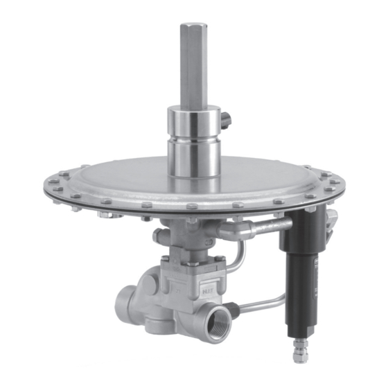
ACE95 Series
Note
Advertisement

Related Manuals for Emerson FISHER ACE95 Series


Summary of Contents for Emerson FISHER ACE95 Series
- Page 1 The recommended pressure limitations are stamped on the accordance with international and applicable regulator nameplate. Some type of overpressure protection codes and regulations and Emerson Process is needed if the actual inlet pressure exceeds the maximum Management Regulator Technologies, operating outlet pressure rating. Overpressure protection Inc.
- Page 2 ACE95 Series Table 1. Body Sizes and End Connection Styles TYPE BODY TYPE BODY SIZE END CONNECTION STYLE 3/4 in. 1 in. CL150 RF Angled Body CL300 RF DN 25 / NPS 1 PN16/25/40 RF Sanitary Flange 3/4 in. ACE95 1 in.
- Page 3 ACE95 Series Description Actuator Case (lower) Hex Nut Hex-Head Machine Screw Actuator Case (upper) LOCATE Spring Shim (Type ACE95 only) GROOVE IN Lower Cage LOWER CAGE Spring (cage) FOR ROLLING DIAPHRAGM Piston (pilot) BEAD Rolling Diaphragm O-ring Cage (upper) LOCATE O-ring GROOVE IN LOWER CAGE...
- Page 4 D102775X014 © 2002, 2022 Emerson Process Management Regulator Technologies, Inc. All rights reserved. 11/22. Americas Asia Pacific The Emerson logo is a trademark and service mark of Emerson McKinney, Texas 75070 USA Singapore 128461, Singapore Electric Co. All other marks are the property of their prospective owners.